home power magazine - issue 020 - 1990 - 12 - 1991 - 01
Bạn đang xem bản rút gọn của tài liệu. Xem và tải ngay bản đầy đủ của tài liệu tại đây (11.48 MB, 67 trang )
2
Home Power #20 • December 1990 / January 1991
Support HP Advertisers!
REAL
GOODS
AD
FULL PAGE
PowerHome
From us to YOU– 4
Results of Reader Survey
Hydro– 6
Kennedy Creek Hydro Systems
Basic Electric– 10
Yer Basic Alternator
Photovoltaics– 12
Experiment at Table Mountain
Efficient Lighting– 15
Lights at Night
Efficient Lighting– 20
Compact Fluorescents on 120 vac
Batteries– 23
EDTA treatment for Lead-acid Cells
Solar Cooking– 27
Heaven's Flame Cooker at work!
Solar Recipes– 29
Chili & Lasagne
Photovoltaics– 31
PV Cell Model
HP Subscription Forms– 33
Subscribe to Home Power
Photovoltaics– 37
No Smoke, No Flame
PV Cost Analysis– 39
The Price of Power
Things that Work!– 40
Ample Power's Energy Monitor
Wind Powered Generators– 42
The Whisper 1000
Contents
People
Legal
Home Power Magazine
POB 130
Hornbrook, CA 96044-0130
916–475–3179
CoverThink About It
"There can be hope only for a society
which acts as one big family, and not
as many seperate ones."
Anwar al-Sadat. 1918-1981.
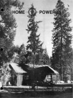
Solar Power at work. The two
home-made solar cookers make dinner.
The 12-module Kyocera PV array
makes about 600 Watts of electricity.
Photo by Bob-O Schultze & Richard Perez.
Larry Behnke
Sam Coleman
Chuck Carpenter
D.W. DeCelle
Barbara Hagen
Kathleen Jarschke-Schultze
Bruce Johnson
Stan Krute
Don Harlan
Kevin Landis
Aubrey Marks
Lyn Mosurinjohn
John Osborne
George Patterson
Karen Perez
Richard Perez
Mick Sagrillo
Bob-O Schultze
Robert Starcher
Sue Starcher
Walt Stillman
Gene Townsend
John Wiles
Issue Printed on recyclable paper,
using soybean based inks, by
RAM Offset, White City, OR
While Home Power Magazine
strives for clarity and accuracy, we
assume no responsibility or liability
for the usage of this information.
Copyright © 1990 by Home Power
Magazine.
All rights reserved. Contents may
not be reprinted or otherwise
reproduced without written
3
THE HANDS-ON JOURNAL OF HOME-MADE POWER
Access
Computing– 44
Computing on 25 Watts
Alternatives– 46
For Spacious Skies…
Things that Work!– 48
Statpower's PROwatt 600 Inverter
System Shorties– 50
Quickies from HP Readers
Happenings– 52
Renewable Energy Events
Code Corner– 54
Is PV going to grow up?
the Wizard Speaks– 55
Solar Power
Letters to Home Power– 56
Feedback from HP Readers
Good Books– 61
Wiring 12 Volts for Ample Power
Writing for Home Power– 61
Contribute your info!
Ozonal Notes– 61
Our Staph gets to rant & rave…
Home Power's Business– 63
Advertisng and other stuff
MicroAds– 64
Home Power's Unclassified Ads
Mercantile Ads– 66
RE Business Access
Index to HP Advertisers– 66
For all Display Advertisers
Home Power #20 • December 1990 / January 1991
4
Home Power #20 • December 1990 / January 1991
From Us to YOU
And the Results Are In
Thanks
Many thanks to all of you who took the time to fill
out the reader survey. Much appreciated!
The Results
A total of 283 readers let us know how they feel.
The most common concern was that Home Power
would go glossy and lose its hands on approach.
This is NOT going to happen. We hope that this
issue will help put those fears to rest. The yes
votes for more pages totaled 70.3%, yes for
recycled paper was 71.0%, going to color got the
lowest percentage at 39.5%. The number of bucks
averaged out at $14.53 with a range from zero to
$60.00.
What We Decided
After much head pounding, hair
pulling and kitty petting a decision
has been reached. Yes to more
pages. Issue 21 will have more
pages. Recycled paper will,
unfortunately, have to wait six to
eight months. The paper we are
currently using, 35# Columbia
Web, is not available in post
consumer paper. That means we
would have to go to heavier 40#
book stock, which has only 40%
post consumer paper. The 40#
book is bleached (nasty dioxin
producing chemicals) and would greatly
increase postage. At this time it would take 4
months just to get this paper and it would increase
production costs by approximately 45% (paper &
postage). Four post consumer recycled paper
mills are due to go on line within 6 to 8 months.
One company is working on post consumer 35#
Columbia Web. This should help to increase the
supply and reduce the cost.
We will stay with color, but only on the non-clay
coated cover. The reason for this is newsstands.
Four of the five distributors now carrying HP asked
for more #19's and increased their standing orders.
We want to spread the word but we have to get
folks to pick it up.
We will continue to use soybean based inks
throughout HP. Black soybean inks are non-toxic,
color soybean inks do contain 6-10% toxic
materials.
The Bottom Line
Here's where the rubber meets the road, as of #21
HP's new subscription rate will go from $6.00 per
year to $10.00. Here are the reasons: 1) more
pages, 2) the U.S. Postal Service will be raising
their rates sometime early in 1991, and 3) we will
be saving part of the $10 for recycled paper.
The Why
You might ask why we are concerned with
magazine distributors and newsstands. If you have
seen or heard any of the many recent programs on
renewables you might have noticed that they ALL
say that renewable energy is the energy of
the future. Not true, it's the energy
of TODAY. Our goal is to help
people prove that they are not
helpless. We can make a
difference right now, no matter
how small. Many small savings
can add up to big solutions!
For instance, if folks only knew
what to do disposable batteries
could become a thing of the past.
This might sound like a small thing
until you think about our planets
resources, land fills, and the toxic
materials in batteries. Or if
everyone in the U.S. went to energy
efficient lighting 30 to 50 power planets could
be eliminated.
We need this information. Our planet needs this
information. Our children need to do things
differently if they are to survive. We hope that
Home Power Magazine contributes to a saner and
safer future.
So here it is. We hope everyone understands.
Karen Perez
5
Home Power #20 • December 1990 / January 1991
Support HP Advertisers!
ALTERNATIVE ENERGY ENGINEERING
AD
FULL PAGE
6
Home Power #20 • December 1990 / January 1991
Hydro
KENNEDY CREEK HYDROELECTRIC SYSTEMS
Richard Perez
©1990 by Richard A. Perez
n the 6,000 foot tall Marble Mountains of Northern
California, it rains. Wet air flows straight from the
Pacific Ocean only forty airline miles away. This
moist ocean air collides with the tall mountains and
produces over sixty inches of rainfall annually. Add this
rainfall with the spectacular vertical terrain and you
have the perfect setting for hydroelectric power. This is
the story of just one creek in hydro country and of five
different hydro systems sharing the same waters.
I
Kennedy Creek
Kennedy Creek is on the west drainage of 4,800 foot tall Ten
Bear Mountain. The head waters of Kennedy Creek are
located in a marsh at 2,500 feet of elevation. The headwaters
are spread out over a 10 acre area and the power of Kennedy
Creek doesn't become apparent until its waters leave the
marsh. After a winding course over five miles in length,
Kennedy Creek finally empties its water into the Klamath
River at about 500 feet elevation. This gives Kennedy Creek
a total head of 2,000 vertical feet over its five mile run.
The volume of water in Kennedy Creek is not very great.
While we weren't able to get really hard data as to the amount
of water, the residents guessed about 500 gallons per minute.
Kennedy Creek is not large by any standards. It varies from
two to eight feet wide and from several inches to about four
feet deep. We were able to cross it everywhere and not get
our feet wet. The point here is that you don't need all that
much water if you have plenty of vertical fall.
The Kennedy Creek Hydro Systems
Kennedy Creek supports five small scale hydroelectric
systems. Each system supplies electric power for a single
household. Each system uses the water and returns it to the
creek for use by the next family downstream.
These systems are not new comers to the neighborhood; they
have been in operation for an average of 7.6 years. These
systems produce from 2.3 to 52 kilowatt-hours of electric
power daily. Average power production is 22 kWh daily at an
average installed cost of $4,369. If all the hydroelectric power
produced by all five Kennedy Creek systems is totaled since
they were installed, then they have produced over 305
megawatt-hours of power. And if all the costs involved for all
five systems are totaled, then the total cost for all five
systems is $21,845. This amounts to an average of 7¢ per
kilowatt-hour. And that's cheaper than the local utility. One
system, Gene Strouss's, makes power for 3¢ a kilowatt-hour,
less than half what's charged by the local utility.
All the power production
data about the Kennedy
Creek hydroelectric
systems is summarized in
the table on page 7. All
cost data is what the
owners actually spent on
their systems. Being
country folks, they are
adept at shopping around
and using recycled
materials. The cost
figures do not include the
hundreds of hours of
labor that these
hydromaniacs have put into their systems.
Let's take a tour of the Kennedy Creek Hydros starting at the
top of the creek and following its waters downward to the
Klamath River.
Above: Gene Strouss's hydroelectric home. They make all their
own power and grow most of their food. Their hydro has made
over 40 kWh daily for the last nine years and at an overall cost of
about 3¢ per kWh. of electric power. Photo by Richard Perez.
7
Home Power #20 • December 1990 / January 1991
KENNEDY CREEK HYDROS
Average Daily Total System
Hydroelectric System's Power Power Power Power
System's Age in Output Output made System cost to date
Operator Years in Watts in kWh. in kWh. Cost $ per kWh.
Gary Strouss 6 2,040 49 107,222 $8,795 $0.08
Stan Strouss 8 180 4 12,614 $3,520 $0.28
Gene Strouss 9 2,166 52 170,767 $5,950 $0.03
Max&Nena Creasy 6 97 2 5,098 $1,295 $0.25
Jody&Liz Pullen 9 120 3 9,461 $2,285 $0.24
AVERAGES 7.6 921 22 61,033 $4,369 $0.18
TOTALS 38 4,603 110 305,163 $21,845
Kennedy Creek as a Power Producer
Total All Systems Cost / Total Power All Systems Made to Date
in Dollars per kiloWatt-hour ($ / kWh.) $0.07
Gary Strouss
Gary Strouss wasn't home the day that Bob-O, Stan Strouss,
and I visited Gary's hydroelectric site. Gary is a contractor and
off about his business. So as a result, we got this info from his
brother Stan and father, Gene (the next two systems down
Kennedy Creek).
Gary's hydroelectric system uses 5,300 feet of four inch
diameter PVC pipe to deliver Kennedy Creek's water to his
turbines. The head in Gary's system is 280 feet. In hydro
lingo, head is the number of VERTICAL feet of drop in the
system. Static pressure is 125 psi at the turbines.
Gary uses two different hydroelectric generators. One makes
120 vac at 60 Hz. directly and the other produces 12 VDC.
The 120 vac system is very similar to the one his father, Gene
Strouss uses and is described in detail below. Gary's 120 vac
system produces 3,00 watts about eight months of the year.
During the summer dry periods, Gary switches to the smaller
12 Volt hydro.
The 12 VDC
system uses a
Harris
turbine that
makes
about 10
Amperes of
current.
The Harris
turbine is fed
from the same pipe
system as the larger
120 vac hydro.
Gary's home contains all
the electrical conveniences,
including a rarity in an AE
powered home- an air
conditioner! The 120 vac hydro
produces about 48 kilowatt-hours
daily, so Gary has enough power for
electric hot water and space heating.
Stan Strouss
Stan's hydro is supplied by 1,200
feet of 2 inch diameter PVC pipe.
His system has 180 feet of head. In
Stan Strouss's system this head
translates to 80 psi of static
pressure, and into 74 psi of
dynamic pressure into a 7/16 inch
diameter nozzle.
Stan uses a 24 Volt DC Harris
hydroelectric system producing
three to ten Amperes. Stan's hydro
produces an average of 180 Watts
of power. This amounts to 5,400
Watt-hours daily. The system uses
no voltage regulation.
The DC power produced by the
hydro is stored in a 400
Ampere-hour (at 24 VDC) C&D
lead-acid battery. These ancient
cells were purchased as phone
Above: Gene Strouss (on the left), and his son Stan,
stand before Gene's hydro. This hydro makes 120 vac at 60
cycles. Gene's system uses no batteries and no inverter. He
consumes the power directly from the hydro. Photo by Richard Perez.
company pull-outs eight years ago. Stan plans to use an inverter to run
his entire house on 120 vac. Currently. he uses 24 VDC for
incandescent lighting. When I visited, there was a dead SCR type
inverter mounted on the wall and Stan was awaiting delivery of his new
Trace 2524.
Stan's system is now eight years old. The only maintenance he reports is
replacing the brushes and bearing in his alternator every 18 months. That
and fixing his water intake filters wrecked by bears.
HydroHydro
8
Home Power #20 • December 1990 / January 1991
HydroHydroHydro
Stan and his father, Gene, own and operate a sawmill and lumber
business from their homesteads. This business, along with raising
much of their own food, gives the Strouss families self-sufficiency.
Gene Strouss
Gene Strouss's hydroelectric system is sourced by 600 feet of six
inch diameter steel pipe connected to 1,000 feet of four inch
diameter PVC pipe. Gene got an incredible deal on the 20 foot
lengths of steel pipe, only $5 a length.
A twelve inch diameter horizontal cast steel Pelton wheel translates
the kinetic energy of moving water into mechanical energy. The
Pelton wheel is belted up from one to three and drives an 1,800
rpm, 120 vac, 60 Hz. ac alternator. All power is produced as 60
cycle sinusoidal 120 vac. The Pelton's mainshaft runs at a
rotational speed of between 600 and 800 rpm. The output of the
alternator is between 1,500 to 2,500 watts out depending on nozzle
diameter. At an annual average wattage of 2,000 watts, Gene's
turbine produces 48,000 watt-hours daily.
The pipe delivers 60 psi dynamic pressure into a 9/16 inch in
diameter nozzle, for summertime production of 1500 watts at 70
gallons per minute of water through the turbine. In wintertime with
higher water levels in Kennedy Creek, Gene switches the turbine to
a larger,13/16 inch diameter nozzle. Using the larger nozzle
reduces the dynamic pressure of the system to 56 psi and produces
2,500 watts while consuming 90 gallons per minute.
Gene's system is nine years old. The only maintenance is bearing
replacement in the alternator every two years. Gene's system uses
no batteries, all power is consumed directly from the hydro. Gene
keeps a spare alternator ready, so downtime is minimal when it is
time to rebuild the alternator. Regulation is via a custom made 120
vac shunt type regulator using a single lightbulb and many parallel
connected resistors. Major system appliances are a large deep
freezer, a washing machine, 120 vac incandescent lighting, and a
television set.
Gene's homestead is just about self-sufficient (which is why he
needs his freezer). Hundreds of Pitt River Rainbow trout flourish in
a large pond created by the Pelton wheel's tail water. The trout love
the highly aerated tail water from the hydro turbine. Gene grew 100
pounds of red beans for this winter and maintains two large
greenhouses for winter time vegetables. Gene Strouss also keeps
a large apple orchard. Gene raises chickens and this, with the trout,
make up the major protein portion of his diet. His major problem
this year was bears raiding the apple orchard and destroying about
half of the 250 trees. For a second course, the bears then ate up
over sixty chickens, several turkeys, and a hive of honey bees.
Gene called his homestead, "My food for wildlife project."
Max and Nena Creasy
Seven hundred feet of two inch diameter PVC pipe sources a Harris
hydro turbine with two input nozzles. Static pressure at the turbine
is about 80 psi from a vertical head of 175 feet. It produces five to
eight Amperes depending on the availability of water. Max and
Nena use 100 feet of #2 USE aluminium cable to feed the hydro
power to the batteries.
Max and Nena's system uses two Trojan L-16 lead-acid batteries for
350 Ampere-hours of storage at 12 VDC. All usage is 12 Volts
directly from the battery. Max and Nena don't use an inverter. The
system uses no voltage regulation and overcharging the batteries
has been a problem. Power production is 97 Watts or 2,328
Watt-hours daily.
The major appliances used in this system are halogen 12 VDC
incandescent lighting, television, tape deck and amplifier. This
system has been operation for the last six years. Nena reports two
year intervals between bearing and brush replacement in their
alternator.
Max works with the US Forest Service and Nena runs a cottage
industry making and selling the finest chocolate truffles I have ever
eaten.
Above: Gene Strouss's hydro plant. The Pelton wheel is on
the left and belted up to the 120 vac alternator on the right.
Photo by Richard Perez.
Above: Max and Nena Creasy's hydroelectric home.
Below: Max & Nena's Harris hydro turbine recharges their 12
Volt system at about six Amps (24 hours a day).
Photo by Richard Perez.
9
Home Power #20 • December 1990 / January 1991
HydroHydroHydroHydro
Jody and Liz Pullen
Jody and Liz's hydro system uses 1,200 feet of 2 inch diameter
PVC pipe to bring the water to the turbine. Jody wasn't sure of the
exact head in the system and without a pressure gauge it was
impossible to estimate. The system works, producing more power
than Jody and Liz need, so they have never investigated the details.
The turbine is a Harris 12 Volt unit. Jody normally sets the Harris
current output at six to ten Amps so as not to overcharge his
batteries. An average output figure for this system is about 120
Watts or 2,800 Watt-hours daily. The power is carried from the
hydro to the batteries by 480 feet of 00 aluminium USE cable.
The batteries are located in an insulated box on the back porch.
The pack is made up of four Trojan T220 lead-acid, golf cart
batteries. The pack is wired for 440 Ampere-hours at 12 VDC. This
system uses no voltage regulation and Jody has to be careful not to
overcharge the batteries. Jody uses all power from the system via
his Heart 1000 inverter. He also uses a gas generator for power
tools and the washing machine. These tools require 120 vac and
more power than the 1000 watt inverter can deliver.
Jody and Liz have used this hydro system for their power for the
last nine years. They report the same biannual alternator rebuild
period. Jody runs a fishing and rafting guide business on the
Klamath River called Klamath River Outfitters, 2033 Ti Bar Road,
Somes Bar, CA 95568 • 916-469-3349. Liz is just about finished
her schooling and will soon be a Registered Nurse.
What the Kennedy Creek Hydros have discovered
Hydroelectric systems are more efficient the larger they get. The
smaller systems have the higher power costs. The largest system,
Gene Strouss's, operates at an incredibly low cost of 3¢ per
kilowatt-hour. And that's the cost computed to date. Gene fully
expects his hydro system to produce electricity for years to come.
Maintenance in these systems is low after their initial installation.
While installing the pipe takes both time and money, after it's done it
is truly done. Only regular maintenance reported was bearing and
brush replacement and trash rack cleaning. The battery based DC
hydros all showed signs of battery overcharging. Voltage regulation
is the key to battery longevity in low voltage hydro systems.
Above: Jody and Liz Pullen's home. Photo by Richard Perez.
A parting shot
As Bob-O and I were driving down Ti Bar Road on our way home,
we passed the Ti Bar Ranger Station run by the US Forest Service.
They were running a noisy 12 kw. diesel generator to provide
power for the ranger station. Which is strange because they are at
the very bottom of the hill with over two thousand feet of running
water above them. And they have five neighbors above them who
all use the hydro power offered by the local creek.
The practical and effective use of renewable energy is not a matter
of technology. It is not a matter of time. It is not a matter of money.
Using renewable energy is just doing it. Just like the folks on
Kennedy Creek do.
Access
Author: Richard Perez, POB 130, Hornbrook, CA 96044 •
916-475-3179.
Hydro Systems: Person's Name, Ti Bar Road, Somes Bar, CA
95568.
DC Hydroelectric turbines mentioned: Harris Hydroelectric, 632
Swanton Road, Davenport, CA 95017 • 408-425-7652.
HARRIS HYDROELECTRIC
Hydro-Power for Home Use
632 Swanton Road
Davenport, CA 95017
408-425-7652
"The best Alternator-based MicroHydro generator I've ever
seen." -Bob-O Schultze
Hydroelectric Editor, Home Power Magazine
Works with Heads
as low as
10'
Prices start
as low as
$595.00
10
Home Power #20 • December 1990 / January 1991
Basic Electric- Alternators
Yer Basic Alternator
Bob-O Schultze - KG6MM
©1990 Bob-O Schultze
ilowatt for kilowatt, using water to spin a generator or alternator has long been recognized as the
most cost-effective way to make electricity. Given that fact, it comes as no surprise that most home
power folks who have the potential to generate hydroelectricity do so. By far, the greatest number
of these DC generating hydrosystems use a common automotive-type alternator, just like the one under
the hood of your favorite go-mobile. Let's take a look into an alternator and see what makes it work.
K
the magnetic field passing a given point is alternating between N
and S at any given time. This is known as an alternating magnetic
field, get it? Add a set of smooth copper slip rings on one side of
the core connected to either side of our coiled conductor so we can
feed some "field current" into our "field winding", spin the whole
shebang, and off we go!
The Stator
The stator is really nothing more than 3 wire conductors spaced
evenly around a ring of iron. Which gives us 3 of the coil/core
combos with the ring of iron acting as the common core for all the
windings. Each of the wires is formed into a number of coils spaced
so that a coil of wire made from conductor #1 is followed by a coil
from #2, followed by #3, followed by a coil from #1, and so on. This
is known as a 120° (apart) three-phase winding. On most
automotive alternators, one end of a coil is tied together with an end
of each of the other coils of wire and is grounded to the frame. The
three remaining ends go to the diodes.
The Diodes
An alternator produces alternating current (ac). To use it to charge
our batteries we need to "rectify" it to direct current (DC) The
diodes, or rectifiers as they're sometimes called, are a series of
electrical one-way valves. They allow current to pass one way and
block it from coming back. When installed on a line carrying ac,
they pass one half of the ac wave and block the other half,
changing the ac to a "pulsating" DC. With the addition of a filtering
capacitor to "smooth out" the pulse, we have DC clean enough to
charge batteries, play rock 'n roll, or whatever.
The Brushes
The brushes sit on the slip rings of the rotor and maintain electrical
contact with the field coil while the rotor is spinning. Wires
connected to the brushes and to a battery provide the field current
necessary to make the field magnetism of the rotor.
Electricity and Magnetism
To understand how an alternator works, let's review some electrical
fundamentals. When you pass an electric current through a
conductor, such as a copper wire, concentric circles of magnetism
are created around the wire. As we increase the current in the wire,
this "magnetic field" grows in strength or intensity. Unfortunately, no
matter how much current we pass thru a straight conductor, the field
around it is too weak to be of value for most applications. If we take
this straight conductor, however, and wind it in a series of loops to
form a coil, the magnetic field intensifies greatly and "poles" are
produced at each end of the coil. These poles are called North and
South. The magnetic lines of force leave the coil at the North pole
and re-enter the coil at the South. If we take an iron core and place
it inside this coil, the magnetic field produced by current passing
thru our conductor is intensified further still, since iron offers a much
easier path for magnetism to pass through than air, the magnetic
lines squeeze down, become more concentrated, and stronger.
Now we've got something to work with!
Yer Basic Alternator
An alternator consists primarily of a rotor, a stator assembly, and a
couple of end frames to hold the stator and rotor bearings so
everything is properly spaced yet doesn't crash into one another.
The end frames are also a handy place to stick a few other
necessary parts like brushes and diodes.
The Rotor
In our alternator, we take this coil and core electromagnet and
mount it between two iron segments with many interlacing "fingers"
which each become "poles". When current is passed thru our
conductor, each of the fingers being on opposite sides of the wire,
pick up the "Pole-arity" of that pole. Consequently, the fingers are
polarized N-S-N-S-N-S etc. When we spin the rotor, the polarity of
11
Home Power #20 • December 1990 / January 1991
How it Works
When we provide a small field current to the
rotor and spin it, whether by water pressure or
the fan belt of your Chevy, a strong magnetic
field is formed at the rotor fingers or poles. As
the rotor passes by the loops of wire in the
stator, the magnetic field cuts across each wire,
causing voltage and current to be "induced" into
these stator windings. Because the poles of the
rotor alternate first South, then North, then South
again, etc., the voltage induced into the stator
windings also alternates between "+" or positive,
zero (between poles), and "-" or negative.
In the stator of our alternator, remember, there
are three separate windings each consisting of
many loops of wire. As the alternating magnetic
field from the rotor passes by each winding, a
separate voltage, or "phase" is induced in each
conductor. Since we have three such
conductors in our stator windings, three phase
alternating voltage is produced.
Why three phase and not just single phase?
Well, you could. In fact, the 110 vac alternator in
Gene Strouss' hydrosystem has many coils of a
single conductor in its stator. Its output is 110
vac single phase – standard home lighting and
appliance power. In our automotive type
alternator, however, weight and size are factors.
The 3 phase arrangement also gives somewhat
more output at lower RPM than single phase and
because the phases overlap one another, the
voltage waveform after it's been rectified to DC is
smoother.
In our alternator, 6 diodes, arranged in 2 banks
of 3 each, take the ac voltage and rectify it by
passing only the negative half of the ac
waveform to ground and passing the positive half
to the "+" output terminal of the alternator and
hence to the battery. That's it!
Access
Author: Bob-O Schultze, Electron Connection,
POB 442, Medford, OR 97501 • 916-475-3401.
KYOCERA
AD
Basic Electric- Alternators
SOUTHWEST REGIONAL ENERGY FAIR
May 17, 18, & 19, 1991
Bernalillo, New Mexico (20 mi. north of Albuquerque)
WORKSHOPS: ACTIVE AND PASSIVE SOLAR - PHOTOVOLTAICS -
ADOBE BUILDING - RENEWABLE FUELS - CONSERVATION - WIND -
GEOTHERMAL - RECYCLING - WOOD - SUNSPACES
PRESENTED BY THE NEW MEXICO SOLAR ENERGY INDUSTRY
ASSOC. INQUIRES REGARDING SPONSORSHIPS, ADVERTISING OR
BOOTHS SHOULD BE DIRECTED TO: JEFF SCHMITT, C/O SEMCO,
2021 ZEARING NW, ALBUQUERQUE, NM 87104 • (505) 247-4522
12
Home Power #20 • December 1990 / January 1991
Experiment at Table Mountain
Bob and Sue Starcher
©1990 by Bob and Sue Starcher
e decided to make owr own power since we were Camp Hosts in a remote campground in the
San Gabriel Mountains of Southern California. And since the campground had no electricity for
the hosts to hook up to. The purpose of this experiment was to test the PV panels we
purchased for use at our retirement home in Northern California.
W
The Setting
We were told by Southern California Edison that to run lines down
the hill from the ski lodge to Table Mountain Campground would
cost $40,000. For this amount, I figured I could put in enough PV
panels, batteries, and inverters to run all three RVs and still have
money left over. I chose to use the equipment I had already
purchased. The power we generated was for the campground Host
and Pay Station signs.
The System
The test system I used had six PV panels with a panel rating of 43
watts (≈2.6 Amperes at 16.5 VDC) each. The PV array was coupled
to a 380 Ampere-hour, 12 Volt battery bank via the Trace C30-A
charge controller. During the month of July, at the peak solar hours
of the day, I recorded 14 Amperes of current at the charge
controller, which was about 1.5 Amperes less than I expected from
the system. The surface temperature of the panels may have
reached a point of some de-rating of the voltage and current. I am
happy with the overall performance of these panels. I purchased
them at an electronic swap meet for a very reasonable price of
$1,035 or $172.50 each. This is approximately $4.00 per Watt. If I
figure the cost per watt on the actual power I seem to be getting 14
A X 16.07 V=225 W=$4.60 per Watt.
The Batteries
I did encounter some problems keeping the battery bank charged
during several weeks of partly cloudy days in August. This is where
the properly sized battery bank comes into play. As a rule of thumb,
I like to use 50 Ampere-hours of battery storage for each Ampere of
current output of the PV array. My array puts out 14 amps so 14 A
X 50 A-h.=700 A-h. of battery storage. My battery bank should have
been 700 Ampere-hours to carry me through the cloudy days. This
Bob Starcher in Fort Jones, CA. A 1200-gallon water storage tank with Flowlight SlowPump & 4 ARCO Photovoltaic modules.
Photo by Sue Starcher.
13
Home Power #20 • December 1990 / January 1991
Component List
1 Trace 2012 inverter $1,090
6 43 Watt PV panels $1,035
1 Trace C-30A charge controller $75
2 US - 2200 6 Volt used golfcart batteries 220 A-h. @ $50
2 Homebrew wooden PV racks, hardware & wire $45
1 110 ft. of #4 wire $30
1 0-15 Voltmeter $15
1 0-30 Ammeter $15
2 Group 24 used RV batteries 80A-h @ $0
1 set inverter cables (free with Trace inverter) $0
Grand Total $2,355
PV Systems
would have prevented the controller from shutting off
the PV array at 3:00 pm each day when the battery
bank had reached the full voltage of 14.4 Volts. The
system was not balanced and I was producing more
power than I could store.
I chose not to spend the money on more batteries
because this was only an experiment. With the 380
Ampere-hours I was working with, I found that with
conservation I could recover the charge to a level of
12.55 Volts with one full day of sun. This is
approximately 80% state of charge. At one point, the
battery was down to 12-12.2 volts, but only for one
night. It took three partly cloudy days to bring it back to
full charge. During this time of discharge and
re-charge, it seemed that only bi-weekly checks of
water usage were needed and only normal small
amounts of water were added. I only used 1/2 gallon of
distilled water in two months.
The PVs
During the installation of this system, I placed the PVs
on a ground mounted wooden rack and placed them at
6° east of true magnetic south with my compass. With
the help of a friend, who is a radio amateur, we worked
up a chart for tilt angle for the Los Angeles area. I set
the PVs at 30° for the end of June. Our chart says
27.5° on June 22. On September 2nd I re-set the PVs
at 35° and our chart says 35° is where they should be
set for September and March. I didn't find a drastic
change in output with the elevation change. For a fixed
mount, I believe it should be adjusted four times each
year, minimum. These times should be December
22nd, March 22nd, June 22nd, and September 22nd.
Our angles worked out to be December 42.5°, March
and September 35° and June 27.5°.
I used #14 stranded wire to wire the panels and #4
stranded wire to make the 55 ft. run to the battery. I
used #8 solid copper wire to ground the PV frames and
negative output line to an 8 ft. ground rod driven into
the ground. This was done to prevent lightning
damage to the panels and charge controller.
Controllers and Inverter
The battery bank, charge controller and meters were
mounted on the front of the trailer as a convenient
place to house these items and get the 12 volt power
into the trailer.
The system provided an average of 1250 watt-hours
per day for the months of June, July and August. The
power was used to run my 19 ft. trailer (black and white
TV, amplified antenna, and DC lights) and two 25 watt
incandescent 12 volt lights on the Camp Host signs.
We used the Trace to power Sue's portable Singer
sewing machine and a 19" color TV during the day.
The Trace also kept the rechargable Dust Buster and
my razor charged. We were able to use the inverter to
provide home comforts to some of our visiting campers,
such as shavers, hair dryers and curlers. Boy, did their
eyes bug out when the generator made no noise and
required no gasoline!
I found no noise or RF interference from the Trace
inverter. The system works very well for RV use.
Conclusion
I learned one very important thing. The battery bank in a PV system CAN BE the
weak link in the overall system if it is NOT sized properly to take care of the
cloudy days and cooler than AMBIENT temperatures. The PV system and
battery storage must be sized to match each other as well as the climate. The
entire system MUST BE BALANCED.
I am also working on a PV system for my retirement home located near Fort
Jones, California. We are presently hooked up to the grid, but our plan is to
disconnect 40% of the home from grid power by the summer of 1991. The
system for our home includes the equipment listed in this article and also eight
more Arco ASI 16-2000 PV panels, a Flowlight SlowPump™ and a Flowlight
Booster Pump. I still have to buy the batteries for the house. The slow pump will
operate directly from the PV panels.
ACCESS
Author: Robert L. Starcher, 422 W. Alosta SP-40, Glendora, CA 91740 •
818-914-4812.
PV panels, charge controllers, inverters and battery data: REAL GOODS
TRADING CO., 966 Mazzoni Street, Ukiah, California 95482
Charge controllers, inverters & meters, system sizing: ALTERNATIVE ENERGY
ENGINEERING, INC., POB 339, Dept. G, Redway, CA 95560
Below: six PV modules on homebrew wooden ground mounting racks.
Photo by Bob Starcher.
14
Home Power #20 • December 1990 / January 1991
SOLAREX
FULL
PAGE
AD
15
Home Power #20 • December 1990 / January 1991
Lights at Night
Using Electronic Light Bulbs on Inverters
Richard Perez
©1990 by Richard A. Perez
ith Winter's short days upon us, now is the time to consider how we are making our light at night.
Shorter days mean not only more hours of lighting use daily, but also reduced power production
from PV modules. Here is information about applying a type of high efficiency light. These
compact fluorescent lights, called "electronic light bulbs", are screw-in replacements for regular
incandescent lamps. They not only save power, but they are silent, have near daylight correct color
rendition, and run without a trace of flicker. And here's the best part– they operate very well on inverters.
W
Lights at night…
The use of artificial lighting at night goes back to the campfire,
through candles & oil/gas lamps and into the age of electricity.
More than one historian claims that the development of civilization
was in no small part attributed to lights at night. Lighting provides
the opportunity to work, learn and play when the sun's down. All
factors contributing to the development of language, art and culture.
Our need for light at night hasn't diminished over the ages. It has
increased. And our ability to make the light we need has also
grown. Technology has reached the point where we need not use
extravagant amounts of power to have lights at night. What we
need is to realize the options that technology has offered us.
The first major advance in electrical lighting was the incandescent
lamp. The lamp (invented by Thomas A. Edison in the dim mists of
history when General Electric's major product was light bulbs not
progress) heats a filament into incandescence. The major physical
effect of the incandescent lamp is not light, but heat. Over 94% of
the electricity pumped into an incandescent lamp goes into heat, the
remaining >6% of the power is converted into light.
Above: Allen Schultze uses an 11 watt OSRAM electronic light bulb to do his homework. The bulb is screwed into a standard
desk lamp and powered by an inverter. It gives Alan all the light he needs. The power source for Allen's home is sunlight, his
family uses a photovoltaic array to make their power. Alan uses a small PV module and battery to power up his radio/cassette
shown on his desk. Photo by Richard Perez.
16
Home Power #20 • December 1990 / January 1991
Efficient Lighting
Enter the fluorescent lamp. The fluorescent lamp uses a glass tube
that is internally coated with phosphors. Phosphors are chemical
compounds that emit visible light when in the presence of electric
fields. A special electronic circuit, called a ballast, was used to
convert the 120 vac power to excite the fluorescent tube (see
George Patterson's article in this issue for techie details on
ballasts). Fluorescent light is four to seven times more efficient at
converting electricity to light than are incandescent lights. Well,
great! Except that early fluorescents had several major warts. One,
they gave off a bluish light that made everyone look pale and
corpse-like. Two, they gave off a flickering light because they were
powered at 60 cycles per second (the human eye can perceive a
flicker at about 30 Hz directly and over 70 Hz. subliminally). And
three, they buzzed like banshees when fed inverter-produced
power. Well, some bright engineers have come up with solutions to
all three of these problems.
The OSRAM Dulux EL Lamps
These lamps are a significant advance in the use of phosphors to
make light. One, the EL lamps use a particular phosphor coating
which produces light that is color correct and virtually
indistinguishable from daylight. Two, they use a switching type
electronic ballast that operates at 35,000 cycles per second instead
of 60 cycles per second. This high frequency ballast eliminates all
traces of flicker in light output. And three, they love running on
inverters. They operate silently on inverters. They will boot most
inverters from standby mode into operating mode.
OSRAM Dulux EL Electronic Light Bulb Data Equivalent Power saved Dollars Dollars
Incandescent over lamp's saved saved
Lamp Lamp Lamp Lamp Dimensions- Inches Lamp lifetime on GRID on RE
Type Cost Wattage A B C Wattage in kWh. 12¢ / kWh. 85¢ / kWh.
EL-7 $23.95 7 5.69 2.25 1.06 25 180 $1.65 $133.05
EL-11 $23.95 11 5.69 2.25 1.06 40 290 $14.85 $226.55
EL-15 $23.95 15 6.88 2.25 1.06 60 450 $34.05 $362.55
EL-20 $23.95 20 8.19 2.25 1.06 75 550 $46.05 $447.55
EL-R 11 $29.95 11 5.88 4.88 50 390 $26.85 $311.55
EL-R 15 $29.95 15 7.25 4.88 75 600 $52.05 $490.05
The EL lamps have standard light bulb bases and will screw into
any standard light bulb socket. And that includes Aunt Millie's 1920
ceramic table lamp with the bronze gilt fruit on the base. What
follows below is a table describing the various OSRAM EL lamps.
The EL-R11 and EL-R15 are equipped with a reflector and function
as spot or task lights.
In this table, there is derived data about the EL lamps savings of
electricity and money. That's right, not only do they work well, but
they also save money by saving electricity. And that not only saves
us money, but also the environmental pollution associated with
making that electricity. The column headed "Equivalent
Incandescent Lamp Wattage" is just that- for example, consider the
EL-15 lamp. In order to get the same amount of light provided by
the 15 watt EL-15, you will need to use a 60 watt incandescent light
bulb. The next column to the right computes the amount of
electrical power (in kiloWatt-hours) that the EL lamp saves over its
10,000 hour lifetime. Next follows the dollars saved columns. This
is computed on the basis of 10,000 hours of operation (for example
a single EL-15 will outlast 10 regular incandescent bulbs). Note that
grid users save money with these lamps at a dirt cheap electricity
cost of 12¢ per kiloWatt-hour (actually it costs all of us much more,
but the grid is not yet charging for environmental consequences).
Renewable energy users pay more (about 85¢ per kiloWatt-hour)
for their electricity, and thereby they save much more by using
efficient lighting.
17
Home Power #20 • December 1990 / January 1991
Efficient Lighting
Let's examine the scenario of replacing the 60 watt incandescent
bulb in Aunt Millie's table lamp with a EL-15. The EL-15 will save
450 kiloWatt-hours of electricity during its 10,000 hour life.
Assuming that the EL runs four hours daily, this amounts to 6.8
years of operation. During that time, the EL-15 will save the grid
connected user about $34. It will save the renewable energy
powered user about $362. It saves our atmosphere tons of carbon
dioxide and pounds of sulphur dioxide. All this from intelligence
applied to Aunt Millie's table lamp.
What about 12 Volt DC fluorescent lighting? At Home Power, we
have tested virtually every type of DC fluorescent made. They have
problems. One, they are 12 Volt and require the special wiring
treatment used in low voltage circuits. Heavy wire is expensive and
difficult to retrofit. Two, they may use hard to find fluorescent tubes
that are mostly not even close to color correct. And third, they cost
about TWICE as much per light as the EL types. This is because
each low voltage fluorescent contains its own micro inverter. And
this point is the death-nell of low voltage fluorescents. It is far
cheaper to buy a small power inverter (120 Watts) and power six EL
lamps than it is to purchase and install six comparable 12 VDC
fluorescents. With more and more systems going to a large inverter
supplying power for all use, these electronic light bulbs fit into the
wiring and constant inverter operation scenario. This price
difference is built into the use of phosphors for lighting. Phosphors
require require high voltage ac excitation to operate. So whether
you buy a 12 VDC or a 120 vac fluorescent, you are buying and
using an inverter. It is simply more cost effective to use one larger
inverter than it is to use a small inverter built into each and every
fluorescent light. A last factor is longevity. In our experience, low
voltage fluorescents have had short lifetimes (<2,000 hours). The
quality of the construction, and thereby reliability, in the low voltage
fluorescents has not approached that of the Dulux EL units.
Inverter testing of the OSRAM Dulux EL Lamps and others
Basically, we took all the EL series lamps mentioned in the table
and plugged them into as many different types of inverters as we
could get our hands on. Actually, we also had compact fluorescents
by five other manufacturers to test at the same time. I'm not going
to waste your time and our paper with those that didn't work, so I am
writing about the best of the lot, the OSRAM EL units. We
measured the lamp's power consumption on the inverter and
compared it to operation on sine wave power input. We installed
the ELs in every place possible in two homes, one where Karen and
I produce Home Power, and the other where Bob-O and Kathleen
run Electron Connection. Bob-O and Kathleen's home is a very
good test because all of their lighting is powered by 120 vac via the
Trace 2012 inverter. We lived with the lamps.
We use two Fluke 87 DMMs to make these measurements. We
tested the EL series on the following inverters: the Trace 2012, the
Heliotrope 2.3 kW. WF Series, the PowerStar 200, the Statpower
100, the Statpower PROwatt 600 and the Heart 1200. In all cases,
the smallest 7 watt EL was able to boot the inverter and hold it on
for operation. The EL series lamps started instantly on all these
inverters. Several other types we tested went into a 20 second
flashing indecision period before starting, while others never did
Above: Aunt Millie's Lamp saves big bucks with an OSRAM
15 watt electronic lightbulb. Photo by Richard Perez.
120 vac Fluorescent Light Comparison
all lights powered by a Trace 2012 Inverter Rated Entire Lamp's Entire Lamp's
Fluorescent Consumption Lamp's Efficiency
Fluorescent Tube at 120 vac Actual Tube Watts
Manufacturer Model Tube Type Wattage in mA. Wattage / Watts Input
OSRAM EL-15W T-4 13 157.5 19.01 68%
Sylvania FC 800 FC8T9 CB/RS 22 277.0 33.43 66%
OSRAM EL-R15W T-4 13 165.1 19.93 65%
OSRAM EL-11W T-4 9 118.7 14.33 63%
Lights of America 5000 1B FC8T9 WW/RS 22 293.0 35.37 62%
Philips SL*18/R40 T-4 20 319.7 38.59 52%
General Electric FCB 401 FC8T9 WW 22 406.0 49.00 45%
18
Home Power #20 • December 1990 / January 1991
Efficient Lighting
start without first booting the inverter. The EL series operated
absolutely silently on all these inverters. We tried the exact same
lamps on the other inverters and they were dead quiet.
Good Places to use ELs
TIME: In any light that spends more than 2 hrs/day on. Period.
IN EXISTING FIXTURES: Their small size make them naturals for
existing incandescent lamp fixtures. The only places we had trouble
putting the EL lamps was in some recessed ceiling fixtures. I have
included the lamp physical dimensions in the table so you can figure
if it will fit or not. In most cases we tried here, they fit. The EL
lamps will screw easily into most desk and table lamps.
WHERE YOU NEED BRIGHT LIGHT: I installed one of the 15 watt
reflector models in a clip-on fixture above Karen's work area. This
EL-R 15 spends about eight hours a day operating. Karen does a
lot of paperwork and her eyes appreciate the bright, natural, silent
and flicker-free light. The design and execution of the reflector
alone is precise and amazing. We have started and run this
particular EL-R15 when it was at temperatures as low as 30°F. We
noticed that it takes all EL lamps about two minutes to warm up and
produce their maximum light output when they are cold.
Bad Places to use ELs
Any lamp that is repeatedly turned on and off (like the light in the
pantry). The lifetime of the EL is primarily determined by its starting
circuit. OSRAM rates the 10,000 hour lifetime of the EL series on
the basis of three hours of continuous operation per turn on. If you
switch the light on and off many times daily, then the EL's lifetime
will be shorter. ELs are not suited for low temperature
environments, like unheated spaces in cold climes. At sustained
low temperatures, the higher efficiency of the EL is not realized.
Techie Details
I am going to refer you to George Patterson's article which follows
this one. George showed up here one weekend with several large
cardboard boxes full of every different type of compact fluorescent
available. We then proceeded to test each one on every inverter. It
took all weekend and we learned more than I can cram in here.
Bottom Line Time
If you are making your own power, you can save very big bucks by
using efficient lighting. Every Watt you save is a Watt you don't
have to produce, store or convert. This adds to fewer batteries,
fewer PV panels, and smaller, more cost-effective systems.
If you rent your power from the grid, you can save small time bucks
by using efficient lighting. What you can save big time is our world.
The kiloWatt-hours of electric power going down the throats of your
light bulbs have expensive consequences. Conservation is the
most potent tool we have against the environmental, financial, &
political effects of our energy dependency.
And after all, it's not like we have to give anything up to use efficient
lighting anymore. The quality of the light that these efficient lamps
produce is the best ever. Only thing better is sunlight.
Access
Author: Richard Perez, C/O Home Power, POB 130, Hornbrook,
CA 96044 • 916-475-3179. I wish to make it clear that: 1) I don't
sell these lights, 2) I'm not paid by OSRAM, or anybody else, to say
nice things about these lights, and 3) All I get out of this is a warm
feeling that you are not wasting your power and thereby our planet.
Makers of the ELs: OSRAM, 110 Bracken Road, Montgomery, NY
12549-9700 • 800-431-9980 • 914-457-4040.
Osram Dulux EL
Compact Fluorescent Lights
EL-11
$23.50
EL-15
$24.50
EL-11 Reflector or
EL-15 Reflector
$28.50
Shipping Included in Cont.USA
Orders of 6 or more deduct 5%
Mix or Match
Electron Connection
POB 442, Medford, OR 97501
916-475-3401
Heliotrope
General
ad
19
Home Power #20 • December 1990 / January 1991
Long after the sun has set, our
lights are still on.
Use the sun to provide your
own source of electricity to
even the most remote homes.
Siemens Solar electric
systems power 12-volt
appliances; lights, T.V.'s,
two-way radios, water pumps,
small refrigerators, telephones
and more. Siemens solar
systems run small a.c. electric
tools and equipment with a
simple inverter.
Support HP Advertisers!
SIEMENS
The Siemens module is the
heart of any solar electric
power system.
• Rugged and environmentally
safe
• Completely quiet
• Engineered for maximum
power
• Reliable and low
maintenance
• Cost efficient
And all UL Listed solar electric
power modules carry Siemens'
10 year warranty.
The New World Leader in
Solar Technology
ATLANTIC SOLAR PRODUCTS, INC.
9351 J PHILADELPHIA ROAD • POST OFFICE BOX 70060
BALTIMORE, MARYLAND 21237
Home Power
with Sun Power
Siemens Solar Industries
WE OFFER:
• Complete line of balance of systems products
• Computerized system sizing
• Installation
• Financing
• Alternate energy products
• Group buy drop shipments
CALL TODAY FOR FREE BROCHURE
Phone 301-686-2500 FAX 301-686-6221
20
Home Power #20 • December 1990 / January 1991
Efficient Lighting
Energy-Efficient Lighting- Compact Fluorescents on 120 VAC
George Patterson
©1990 by George Patterson
ompact fluorescent lights are one of the most energy-efficient lamps available on the market today.
They produce 3 1/2 times more lumens per watt than incandescent lights and 7 to 13 times the
lamp life of a standard "A" type incandescent. The lamps use 70% less power than standard
incandescents. Modern types use high frequency electronic ballast and produce silent, flicker-free light.
These lamps are color correct. They produce light that is a very good imitation of daylight. We are seeing
a revolution in lighting!
Compact Fluorescent Lamp Data
The data in the table shows performance
data for six compact fluorescent lamps
and two types of incandescent lamps.
Lumens are a unit of light intensity and
ranks the lamps by brightness (the
higher the lumen value the more light the
lamp produces). Lumens per watt
shows how efficient the lamp is. Note
that the compact fluorescents are about
six times more efficient than
incandescents. The lifetime (in hours) is
rated by the manufacturer assuming that
the lamp remains burning for three hours
when switched on. Minimum starting
temperature is just that, the lowest temperature at which the lamp
will reliably start. Color temperature is a scientific system for
measuring the spectral output of a light producing object. In the
color temperature scheme, the object color is related to a black
body at a certain temperature in degrees Kelvin (°K.). The color
rendition index is more easily understood. The color rendition index
of daylight is 100 by definition. The closer a lamp's color rendition
index is to 100, the closer its color is to daylight. OK! Are all of
these lamps real? How do they apply to real life?
The fluorescent light as a system
The lighting fixture is truly an energy system with four
elements - 1) Input power, 2) Ballast, 3) Starter, and 4)
Fluorescent tube. The efficiency and performance of the
system is dependent on the interaction of all four
elements. Change any one element and the light's
performance and efficiency changes.
The reality of lighting is that we are not going to get
something for nothing. Of course, in trying to do so we are
likely to take ourselves to the cleaners. There is no
substitute for doing our homework and making decisions
based upon actual experiences. The 10,000 hour life
figure quoted for most compact fluorescent tubes is just a
starting point. The truth is that we may get anywhere from
2,000 to 20,000 hours from the same tube depending on
the ballast type and operating environment. The light
output from a 13 watt compact fluorescent tube may be
900 lumens at 75° F (100%), 720 lumens at 120° F. and
450 lumens at 40° F. This is especially a problem where
housings and lighting fixtures trap heat inside, or they are
used outdoors in the cold A typical graph of the
operating temperature characteristics is shown at right.
Note that the efficiency we seek so dearly is affected by
the position of the base.
Ballast and tube life on inverters ( square wave ) may be cut in half
compared to use on true sine wave for 120 VAC applications. On
modified sine wave inverters there are no known problems, but the
jury is still out.
Tube Life and Starting
The electronic ballast may deliver promised efficiency, but the
design of the starting circuit is critical. Some compact fluorescent
tubes have built in glow discharge starters, while others use
pre-heat filaments for starting. Pre-heat filaments require external
starting circuitry. Life of compact fluorescent tubes designed for use
C
Compact Fluorescent Lamp Data
Lamp Initial Lumens Lifetime Min. Start Color Color
Type Lumens per Watt in hours Temp. Temp. Index
7w. twin tube 400 57 10000 0 °F. 2700 °K. 82
9w. twin tube 600 67 10000 25 °F. 2700 °K. 82
13w. twin tube 900 69 10000 32 °F. 2700 °K. 82
13w. quad tube 860 67 10000 32 °F. 2700 °K. 82
18w. quad tube 1250 69 10000 32 °F. 2700 °K. 86
26w. quad tube 1800 69 10000 32 °F. 2700 °K. 86
25w. Incandescent 260 10 1500 2500 °K. 91
21
Home Power #20 • December 1990 / January 1991
with external starting circuits (rapid start, pre-heat, and electronic
ballasts) is determined by the design of the starting circuit. The life
of a fluorescent tube with built-in glow discharge starter is primarily
determined by the life of the starter. Starter life in these tubes
varies widely with ballast design. If the fellows that designed the
ballasts did a good job, then the starter will last the 10,000 hour life
of the tube. If the ballast is not properly designed we can expect life
times as short as 2,000 hours.
Ballasts
The newly-developed high power factor coil capacitor ballasts for
120 VAC have energy efficiencies similar to electronic ballasts.
When operated at normal AC line frequency (60 Hz.) the color
temperature is 2700° K. By operating compact fluorescent lamps
on an electronic ballast at high frequency, 25 khz to 35 khz, the
lamps' phosphors are about 14% to 17% more efficient at producing
light and flicker is eliminated. The color temperature drops from
2700°K to about 2300°K.
Very few residential ballast designs address the power factor
requirements imposed by fluorescent lamps. Power factor relates to
the lag between current and voltage and values less than 1.0
translate into wasted energy. Some ballasts have power factors as
high as 0.9, but many fall short with values as poor as 0.2.
Normally, coil capacitor ballasts have a power factor of 0.2 to 0.4,
however, high power factor (HPF) designs achieve values as high
as 0.9. Electronic ballasts usually have power factors above 0.6
and the more expensive and bulky designs above 0.9.
The OSRAM Corporation, a Siemens company (the same people
that purchased ARCO Solar!), is one of the industry leaders in both
compact fluorescent lamp and electronic ballast manufacturing.
Osram has a line of 12 VDC and 120VAC/DC ballasts that are
available only in Europe. These commercial grade electronic
ballasts have a power factor greater than 0.9, and will soon be
available in the USA in 5 to 26 watt sizes.
Dulux EL Electronic Light Bulbs
Residential grade OSRAM DULUX™ EL lamps (Electronic Light
Bulbs) are available in the USA right now. These are for retrofit
applications and have medium bases that replace incandescent
light bulbs. These lamps may be used on inverters at 120VAC and
there is no hum! The power factor for these DULUX™ Electronic
Lightbulbs is 0.6 to 0.7. Its built-in ballast is designed with a full
wave bridge rectifier capacitor input filter followed by a 35 kHz
oscillator to drive the fluorescent tube. All of this is integrated and
the expected tube life and ballast life is well matched. As a result of
this design, these electronic light bulbs may be operated on DC or
120VAC. Since the capacitor acts as a peak detector of the 120 V
RMS AC, the DC required would be around 165 V. This may be
only interesting, but I thought that I would mention it. Also, these
electronic light bulbs have received FCC Part 18C certification for
residential use. This means that they aren't going to interfere with
radios or TVs. Most magnetic ballasts have never been tested by
the FCC, they can be very noisy and interfere with radios and TVs.
We have learned that coil capacitor ballasts produce much more
INPUT POWER
maybe from:
Grid
or Inverter
or Generator
BALLAST TYPE
maybe:
High Freq. electronic
or Low Freq. Electronic
or Coil & Capacitor
STARTER TYPE
maybe:
Glow Discharge
or Pre-heat Filament
or Rapid-start Filament
PHOSPHOR TYPE
maybe:
Color Correct
or maybe not.
Fluorescent Lighting is a System
for it to give color correct, efficient & long-lived light all parts must be in proportion and harmony
Efficient Lighting
22
Home Power #20 • December 1990 / January 1991
heat than electronic ballasts. In fact, to get UL approval, a
compact fluorescent light must operate with an internal
temperature below 120 °F. The lighting industry is developing
low temperature electronic ballasts. They cost more, but have
advantages. If we let the fixture manufacturers know we want
efficient, long-lived lights, they are with us.
Conclusions
Compact fluorescent lighting systems are much more efficient
than incandescent lighting. We see about four times the
lumens per watt as compared to incandescent. There are
more efficient systems than the compact fluorescent, but they
usually aren't suitable for indoor use. Recently, fluorescent
lighting has become much better at color rendition and can
start almost as rapidly as incandescent lamps. With the
emergence of electronic ballasts, heat dissipated in the ballast
has been reduced, and the performance of fluorescent lamp
starting improved.
Why bother?
Energy savings!!! & $$$ Don't forget that your local power
utility ( maybe even you ! ) don't have to produce as much
energy to feed your lighting needs.
Ecological Benefits!!!
CO
2
from burning fossil fuels adds to the greenhouse effect
and global warming. Acid rain kills trees and fish in lakes.
Access
George Patterson, 3674 Greenhill Road, Santa Rosa, CA
95404.
Osram Corporation, 110 Bracken Road, Montgomery, NY
12549-9700. • 800-431-9980 or 914-457-4040
Efficient Lighting
ENERGY DEPOT
Bobier
Electronics
AD
23
Home Power #20 • December 1990 / January 1991
New Life for Sulphated Lead-Acid Cells?
Richard Perez
©1990 by Richard Perez
ver the years I have tried many chemical treatments supposed to rid a cell of sulphation. None of
them made any perceptible difference. A strange and devious set of circumstances has led us to
the successful chemical removal of sulphation from six lead acid cells. Not only are the
circumstances odd, but the chemical used, EDTA, is benign– in fact, it is used as a human food
preservative.
O
The Patients
The sulphated Trojan L-16W lead-acid batteries numbered four and
were the victims of a messy divorce. The pack was less than two
years old when its owners had a parting of the ways. The husband
took off for parts unknown. The wife left the house vowing never to
return. And she left ALL the lights on when she departed. This
system was sourced only by an engine/generator, with no PVs to
help out. After several days the batteries were totally discharged.
The batteries then sat discharged, with the lights switched on, for
the next three months.
The ailing pack was transported to Electron Connection for disposal
as part of the whole divorce rigamarole. Upon inspecting the cells
through the filler holes, we say vast amounts of white moss covering
all the plate assemblies. Or at least we assumed there were plates
in there somewhere because all we could see was an even blanket
of moldy looking lead sulfate. Seven of the twelve cells were very
low in water. Our job was to assess what these batteries were
worth. In order to do this we attempted to recharge them and see
how they held the charge. Open circuit voltage of the cells
averaged 0.7 Volts.
We placed the batteries on a four panel Kyocera J48 PV array (≈12
Amps) and the voltage immediately shot to 15 Volts where the
regulator cut in. The amount of current accepted by the four
L-16Ws was 0.4 Amps. We left the L-16Ws on the array for five
days, but they never did accept a charge. We then tried discharging
the batteries. They (all four 125 pound batteries) ran a 28 Watt car
tail light for about three minutes. This gave us an electrical capacity
of about 0.05 Ampere-hours per cell that originally had a capacity of
350 Ampere-hours. A classic case of sulphation ruining virtually
new, high quality batteries. We pronounced the cells toxic waste
and told the principals involved that the batteries were worthless. In
fact, worse than worthless because someone had to responsibly
dispose of them. The original owners promptly disappeared and left
us holding the batteries. They sat, forlorn and unloved, in the
battery area, side by side with new cells destined for caring homes.
In another reality…
My friend, George Patterson, a battery techie second to none, ran
into an article in an obscure British antique motorcar publication that
described using a chemical called EDTA to remove sulphation from
old lead-acid batteries. I related to him the story of the orphaned
L-16Ws and, to make a very long story short, we decided to give it a
try on these virtually new, but severely sulphated batteries.
EDTA, what is it?
It is an organic acid, a chemical cousin of vinegar. EDTA stands for
the entire name of the compound which is, "ETHYLENEDIAMINE
TETRAACETIC" Acid. EDTA is used for many chemical jobs, but
perhaps the most amazing is as a food preservative. I noticed it on
the list of ingredients of a can of Slice® orange pop I drank. In
chemical techie terms, EDTA is a "chelating agent". That means it
likes to bond to metallic ions (like lead sulfate). While EDTA is not
the sort of stuff you want to eat by the teaspoon (the label carries
warnings about getting it in the eyes or nose), it is a relatively
innocuous chemical with which to attack the sulphated nastiness of
those L-16Ws. I admit to being skeptical. I thought we were
wasting our time. How could something contained in orange pop
help these severely sick cells?
The Operation
George Patterson located and purchased 500 grams of EDTA from
a local chem lab that specializes in the chemical testing of wine.
The cost was low, under $15 for the EDTA and another ten bucks
for rush shipping. George then did an essential duty in this entire
process. He came up to HP Central in Hornbrook and got me off
my butt to actually perform this experiment. George could have
shipped me the EDTA, but he knew my faith in this project was so
low that I'd get it done some time next century.
We decided to operate on two of the L-16Ws and leave the other
two untreated as controls for the experiment. We had only sketchy
information from the British motorcar pub. It described a teaspoon
in every cell (hold the milk and sugar) and let sit for several hours.
It neglected to mention the size of the cell, but George and I
assumed that an antique motorcar would have a fairly small battery-
about 70 Amp-hrs. So we upscaled the amount of EDTA to 2
Tablespoons to match the larger (350 Ampere-hour) L-16W cells.
What follows is a step by step description of what we did:
PLEASE NOTE: These operations involve handling sulfuric acid
electrolyte. We used acid resistant Norex lab coats, rubber boots,
rubber gloves, and safety glasses. If you try these operations
without this safety gear, then you are risking injury. Play it safe.
1 We drained the old electrolyte from all six of the cells. Now this
reads easier than it does. An L-16W battery weighs 125 pounds
and contains 9 quarts of sulfuric acid in its three cells. Be careful
not to drop the battery or spill the acid electrolyte. Reserve the old
electrolyte in secure containers and dispose of it properly through
your local battery shop.
2 We rinsed all the cells with water and drained them.
3 We added 2 Tablespoons of EDTA to each cell and refilled each
cell with hot (≈120°F.) tap water.
4 We left the cells to merrily bubble (the EDTA/lead sulfate reaction
is exothermic- it gives off heat) for about two hours.
5 We then drained the cells and repeated steps 2, 3, and 4 once
again. We could see the sulphation disappearing, but one
treatment had not got it all. Actually, two treatments didn't either
because there was still some sulphation there after the second go
Batteries
24
Home Power #20 • December 1990 / January 1991
round.
6 We rinsed each cell with distilled water and drained it.
7 We refilled each cell with new (sulphuric acid in solution with
distilled water- specific gravity 1.260) lead-acid electrolyte.
The Operation was a success?
After spending all day lifting and draining L-16Ws, George and I
were sore and ready for a few beers. This technique is not
recommended to the frail. If I were to do it again, I would build a
cradle to hold and invert these heavy batteries. Doing it by hand is
tiresome, risky, and invites injury.
Neither of us was convinced that we had accomplished much
beside some heavy sweating dressed in kinky moon suits. We left
the L-16Ws, disconnected and unused, in the basement battery
area. Every time I passed by, I would wire the pack of two
rejuvenated batteries into the PV array for some quickie recharging.
I had no time to run any sustained recharging or testing at that point
because we had another issue of Home Power going to press.
It was not until six weeks later that Scott Hening, our summer intern,
hooked up the EDTA treated L-16Ws into a working system. This
system is sourced by two ancient, anemic SolaVolt PV modules.
The system is simple: the PVs and the two L-16Ws. This system
provides power for lighting in Bob-O's spare trailer which houses
dignitaries and heads of state visiting HP Central. Here the EDTA
treated batteries received about 3 to 4 amps as long as the sun was
shining. Since this system is seldom used, the batteries received a
constant daily overcharge for about eight weeks. Bob-O kept on top
of the cells' water levels and refilled them as needed with distilled
water.
Since the trailer was seldom used, and no one staying there
complained of dead batteries, we just left the L-16Ws alone. Since
the system had no instrumentation, it was hard to tell how much
improvement the EDTA treatment did.
Enter a pressing need
Then all of a sudden (in the space of six days) one of the L-16Ws in
the main Home Power system (4@ L-16W) at Agate Flat developed
a shorted cell. As distressing as it was to lose an eleven year old
L-16W battery, it was fascinating to watch and record the death of
one of its cells. The shorted cell dramatically unbalanced the
remaining three L-16Ws in the pack. I had to do something quick. I
disconnected the series string of two L-16Ws with the bad cell.
Putting a new L-16W in this eleven year old pack was out of the
question. I started thinking used battery and imagined the EDTA
treated L-16Ws. Next day, I removed one of the EDTA treated
L-16Ws from Bob-O's trailer and inserted it the main Home Power
battery. I had trouble choosing the best of the two EDTA treated
batteries. I went for the one that had the least voltage variation
between cells.
EDTA treated L-16W performance
I had no idea what to expect. The last time I tested the sulphated
L-16W it wasn't able to power up a car tail light. I inserted it into the
main pack as follows in the illustration below. I gave each cell a
number and recorded data on the performance of the battery on a
cell by cell basis. The L-16W battery containing cells 1, 2, and 3 is
the EDTA treated battery. The remaining L-16Ws (cells 4 through
12) are the original, untreated, eleven year old batteries.
What happened?
I'll cut to the chase here. The L-16W treated with EDTA had
regained enough of its electrical capacity to function as an equal
element with the battery. It works! What follows below is data from
all cells making up this battery under a variety of conditions.
Detailed in the tables on page 25 are a variety of data, here's a
score card to help tell the players:
Battery Data
1. the date. 2. the battery Ampere-hour Meter reading which
indicates the pack's State of Charge (minus indicates discharge
amp-hrs.). 3. the discharge or charge rate in Amperes (minus
indicates discharge).
Individual Cell Data
4. the voltage of each cell. 5. the absolute cell voltage deviation
from the average cell voltage. 6. the average battery (that's three
Cell 12 Cell 11 Cell 10
TROJAN
L-16W
Cell 6 Cell 5 Cell 4
TROJAN
L-16W
Cell 9 Cell 8 Cell 7
TROJAN
L-16W
Cell 3 Cell 2 Cell 1
TROJAN
L-16W
POSITIVE
12 VDC
at
700 Amp-hrs.
Cells 1 through 3
are the EDTA
treated cells.
Cells 4 through 12
are 11 year old
untreated cells.
NEGATIVE
Batteries
25
Home Power #20 • December 1990 / January 1991
Batteries
Date: 10/21/90 Date: 11/2/90
Amp-hrs. -61 Amp-hrs. -53
Amperes -6.4 Amperes -8.4
Absolute Average Absolute Average
Cell Cell Cell V. Battery V. Cell Cell Cell V. Battery V.
# Voltage Deviation Deviation # Voltage Deviation Deviation
1 2.051 0.00058 0.00586 1 2.056 0.00083 0.00594
2 2.048 0.00358 2 2.054 0.00117
3 2.065 0.01342 3 2.071 0.01583
4 2.051 0.00058 0.00325 4 2.052 0.00317 0.00583
5 2.051 0.00058 5 2.053 0.00217
6 2.043 0.00858 6 2.043 0.01217
7 2.051 0.00058 0.00125 7 2.054 0.00117 0.00117
8 2.050 0.00158 8 2.054 0.00117
9 2.050 0.00158 9 2.054 0.00117
10 2.058 0.00642 0.00714 10 2.062 0.00683 0.00728
11 2.058 0.00642 11 2.062 0.00683
12 2.043 0.00858 12 2.047 0.00817
Average Cell Voltage 2.052 Average Cell Voltage 2.055
Cell Voltage Standard Deviation 0.006244 Cell Voltage Standard Deviation 0.007259
Max. Cell Voltage Difference 0.022 Max. Cell Voltage Difference 0.028
Date: 11/7/90 Date: 11/19/90
Amp-hrs. -29 Amp-hrs. -214
Amperes -2.5 Amperes -2.1
Absolute Average Absolute Average
Cell Cell Cell V. Battery V. Cell Cell Cell V. Battery V.
# Voltage Deviation Deviation # Voltage Deviation Deviation
1 2.114 0.00508 0.00903 1 2.083 0.00075 0.00758
2 2.110 0.00908 2 2.078 0.00425
3 2.132 0.01292 3 2.100 0.01775
4 2.120 0.00092 0.00164 4 2.082 0.00025 0.00258
5 2.121 0.00192 5 2.082 0.00025
6 2.117 0.00208 6 2.075 0.00725
7 2.117 0.00208 0.00142 7 2.092 0.00975 0.00575
8 2.118 0.00108 8 2.077 0.00525
9 2.118 0.00108 9 2.080 0.00225
10 2.125 0.00592 0.00697 10 2.087 0.00475 0.00658
11 2.126 0.00692 11 2.083 0.00075
12 2.111 0.00808 12 2.068 0.01425
Average Cell Voltage 2.119 Average Cell Voltage 2.082
Cell Voltage Standard Deviation 0.006317 Cell Voltage Standard Deviation 0.008203
Max. Cell Voltage Difference 0.022 Max. Cell Voltage Difference 0.032
cells in a case) voltage
deviation. Note EDTA
treated cells' data (Cells #1,
#2, & #3) are printed in bold
type.
Derived Cell Data
7. average cell voltage. 8.
cell voltage standard
deviation (computed via
standard statistical
method). 9. maximum cell
voltage difference.
What the data means
What we are looking for are
differences in voltage
between cells. Which is
why the average cell
voltage and deviations from
average cell voltage are
computed. A maximum cell
voltage difference greater
than 0.05 VDC, under light
discharge (<C/40) means
the cells are unbalanced.
This measured by
subtracting the voltage of
the highest cell from the
voltage of the lowest cell.
Note that on all four test
discharge runs (10/21/90,
11/2/90, 11/7/90, and
11/19/90) all the cells
making up the pack show
about the same voltage. In
fact, some of the EDTA
treated cells are showing
higher voltages than some
of the non-treated cells.
Bottom line is that the
EDTA treated cells are
functioning in as a series
parallel element in a battery
pack. Before treatment
these very same cells
couldn't store enough
power to operate a small
light blub for five minutes.
To date I have discharged
the test battery to the depth
of 214 Ampere-hours
(indicated by the Cruising
Equip. Amp-hr. meter) from the test battery. The EDTA treated cells
are continuing to function within the pack with less than 0.02 VDC
difference from untreated cells.
An alternative to the dump and refill method
The British motorcar publication recommended just adding the
EDTA to the cells and that's all. We went into the dump and rinse
madness on our own. Now, EDTA is supposed to work by just
adding the compound to the cell. No draining, no rising and no
electrolyte replacement. We are trying this technique with the
remaining two sulphated L-16Ws and will publish the data when we
get it.
How you can help…
This experiment seems to have worked. We would appreciate
verification from anyone else who tries it. After all, if you are sitting
on top of a heavily sulphated lead-acid pack, what do you have to
lose? EDTA is cheap and it may restore lost electrical capacity to
sulphated lead-acid cells. We would appreciate any feedback from
those trying our dump and flush technique or those simply adding
EDTA to the cells and just leaving it there. As a very general rule of