practical wireless số 2006 06
Bạn đang xem bản rút gọn của tài liệu. Xem và tải ngay bản đầy đủ của tài liệu tại đây (10.4 MB, 68 trang )
June
2006
£3.00
p
pwp
ct
uil The P dbu 9/1 MH F Mo l
Build
a sensitive
wavemeter
ra r pa
Ha y L s de T le
radio repairs
Harry G3LLL’s Trade Tales
project
Build The Poundbury 9/10MHz IF Module
ev
SDR-1000
software radio
reviewed
o es i
n u 144 Hz n t Ru s
antenna workshop
Polar Plotting with G3LDO
contesting
Annual 144MHz QRP Contest Rules
antenna workshop
Polar Plotting with G3LDO
Copyright © PW PUBLISHING LTD. 2006. Copyright in all drawings, logos, photog aphs and articles published in Practical Wireless is fu ly p otected and ep oduction in whole or part is exp essly forbidden.
All reasonable precautions are taken by Practical Wireless to ensu e that the advice and data given to our readers a e eliable. We canno however gua antee it and we cannot accept legal responsibility
for t Prices a e those current as we go to p ess.
Published on the second Thursday of each month by PW Publ shing Ltd., Arrowsm th Court, Station App oach, B oadstone, Dorset BH18 8PW. Tel: 0870 224 7810 Printed in England by Holb ooks P inte s Ltd.,
Portsmouth P03 5HX Distributed by Seymour, 86 Newman St eet, London , W1P 3 D, Tel: 0207-396 8000, Fax: 0207-306 8002, Web http //www seymourco uk. Sole Agents for Aust alia and New Zealand -
Go don and Gotch (Asia) Ltd.; South Africa - Cent a News Agency. Subscriptions INLAND £32, EUROPE £40, REST OF WOR D £49, payable to PRACTICAL WIRELESS, Subscription Department PW
Pub ishing Ltd., Arrowsm th Court, Station App oach, Broadstone, Dorset BH18 8PW. Tel: 0870 224 7830 PRACTICAL WIRELESS is sold subject to the following conditions, namely that it shall not, w thout
written consent of the publishers fi s having been given, be lent, re-sold, hi ed out or otherwise disposed of by way of t ade at mo e than the ecommended selling price shown on the cover, and that it shall
not be lent, re-sold, hi ed out or othe wise disposed of in a mutilated condition or in any unauthorised cover by way of T ade, or affixed to or as part of any publication or advertising, lite ary or pictorial
matter whatsoever. Practical Wireless is Publ shed monthly for $50 per year by PW Publishing Ltd., Ar owsm th Court, Station App oach, B oadstone, Dorset BH18 8PW, Royal Mail International, c/o
Yellowstone International, 87 Burlews Court, Hackensack, NJ 07601. UK Second Class Postage paid at South Hackensack. Send USA add ess changes to Royal Ma l Inte national, c/oYellowstone
Inte national, 2375 Pratt Bouleva d, Elk G ove Village, IL 60007-5937. The USPS (United States Postal Se vice) number for Practical Wi eless is: 007075.
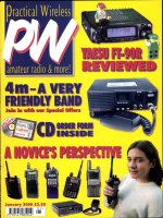
The cover shows an aerial
shot of the ever growing
village of Poundbury, near
Dorchester in Dorset,
which Tony G4CFY chose
as the name of his latest
project. The reason for this
is that the circuit forms part
of a larger item, so is
effectively a work in
progress, just like
Poundbury village. As you
will see our Art Editor
Steve Hunt has cleverly
blended the breadboard
photo onto the aerial shot
in a seemless fashion -
clever eh?
Cover subject
15 Technical for the Terrified
In his continuing series aimed at taking the
fear out of radio maths, Tony Nailer
G4CFY gives a brief overview of the
classes of amplifier operation.
18 The Poundbury Part 1
Tony Nailer G4CFY describes the design
and working of his s.s.b. transmitter and
receiver i.f. unit. An ideal project to ‘grow
on’!
22 Single Side Band Operating
on 144MHz
Whether you’re preparing for a contest or
just want to enjoy a spot of v.h.f. single side
band operating, Joe Butt G0JJG
encourages you to have a go and have
some fun.
24 In The Shop
Harry Leeming G3LLL has spent many
years solving radio repair problems. So, in
this new bi-monthly series he’s sharing
experience of awkward customers,
together with tried and tested methods
from his days in the radio trade.
30 Sensitive Wavemeter
Why not try your hand at building a
sensitive wavemeter? James Brett G0FTP
shares his design with you.
36 SDR-1000 Flex-Radio Review
You’ll either love it or hate it, but software
based radio systems are very much a
reality. Robin Trebilcock GW3ZCF puts
the SDR-1000 from Flex-Radio to the test
and enjoyed the experience as you’ll
discover in his comprehensive review.
6 Keylines Topical chat and comments from our Editor.
This month the topics under discussion by Rob
Mannion G3XFD is the increasing interest in 7MHz c.w.
and a reminder about ‘Silent Keys’.
7 Amateur Radio Waves You can have your say! There’s a
varied and interesting selection of letters this month as
the postbag’s bursting at the seams again with readers’
letters. Keep those letters coming in and making ‘waves’
with your comments, ideas and opinions.
8 Amateur Radio Rallies A round-up of radio rallies taking
place in the coming months.
9 Amateur Radio News & Clubs Keep up-to-date with the
latest news, views and product information from the
world of Amateur Radio with our News pages - the news
basket’s been overflowing so, there’s a bumper dose this
month. Also, find out what your local club is doing in our
club column.
50 VHF DXer This month David Butler G4ASR has news of
a new state-of-the-art 144MHz beacon, as well as your
reports.
54 HF Highlights Carl Mason GW0VSW has the latest
news from the h.f. bands and even though some bands
have been quieter the postbag’s still bursting at the
seams!
59 In Vision Graham Hankins G8EMX rounds up the latest
news from the ATV scene.
60 Book Store If you’re looking for something to
complement your hobby, check out the biggest and best
selection of radio related books anywhere in our bright
and comprehensive revamped Book Store pages.
63 Bargain Basement The bargains just keep on coming!
Looking for a specific piece of kit? Check out our
readers’ ads, you never know what you may find!
64 Subscriptions Want to make sure you don’t miss a
single issue of your favourite radio read then why not
subscribe to PW in one easy step?
65 Topical Talk This month Rob G3XFD chats about the
various types of antennas and which ones seem to be
the most popular with Radio Amateurs.
features
regulars
June 2006
On Sale 11 May
Vol. 82 No. 6 Issue 1190
(July Issue on sale 8 June)
Published by
PW Publishing Limited
Ar owsmith Court
Station App oach
BROADSTONE
Dorset BH18 8PW
Directors: Stephen Hunt & Roger Hall
Editorial Department
☎ 0870 224 7810
Fax: 0870 224 7850
Editor
Rob Mannion G3XFD/EI5IW
Production Editor
Donna Vincent G7TZB/M3TZB
Technical Editor
NG (Tex) Swann G1TEX/M3NGS
Art Department
☎ 0870 224 7820
Fax: 0870 224 7850
Art Editor
Stephen Hunt
Typesetting
Peter Eldrett
Sales Department
Fax: 0870 224 7850
Advertisements
Roger Hall G4TNT
☎ 0207 731 6222
Advertisement Administration
Joan Adams
☎ 0870 224 7820
Book Orders
☎ 0870 224 7830
Subscription Administration
Webscribe
Practical Wireless Subscriptions
PO Box 464
Berkhamsted
Hertfordshire HP4 2UR, UK
www.webscribe.co.uk
☎ 01442 879097
Fax: 01442 872279
Finance Department
☎ 0870 224 7840
Fax: 0870 224 7850
Finance Manager
Alan Burgess
Finance Assistant
Margaret Hasted
PW Publishing Website
www.pwpublishing.ltd.uk
All our 0870 numbers are charged at the BT Standard National Rate
42 QRP Contest Rules
Dr Neill Taylor G4HLX introduces the
rules for the for the 23rd annual 144MHz
PW QRP Contest, reminding us all that it’s
just as much about taking part, having fun
and experimenting as winning. Go on have
a go!
46 Valve & Vintage
Come and take a peek inside Aladdin’s
cave as we join Phil Cadman G4PCJ in
the PW vintage wireless ‘shop’ where he’s
busy identifying unusual valves.
48 Carrying on the Practical Way
The m.o.s.f.e.t. lives again, so says
George Dobbs G3RJV in his monthly
column as he encourages you to switch on
that soldering iron once more.
50 Antenna Workshop
Peter Dodd G3LDO gets ‘plotting’ as he
tries out PolarPlot, a piece of software that
can plot the polar diagram of your antenna
and display it on your computer screen.
Practical Wireless
5
Page 42
june 2006
contents
Background Photograph: Commission Air. Copyright
of the Duchy of Cornwall and reproduced by kind
permission
SDR Photo: Robin Trebilcock GW3ZCF
Poundbury Board: Tex Swann G1TEX
O
ver the extended Easter Bank
Holiday weekend I thoroughly
enjoyed catching up on the ‘air
time’ on the bands I’ve missed
over recent months.
Using my newly-erected 7MHz dipole I
worked stations all over the UK (including an
Orkney Islands ‘Islands on the Air’ station),
Ireland, Europe and occasionally beyond,
using c.w. and s.s.b. It’s a long time since I
dedicated a long weekend to chatting on the
air and the pleasures of this aspect of our
hobby soon came flooding back to me!
What I found particularly interesting on
7MHz were the number of c.w. stations to be
found over the weekend. Nothing surprising
there perhaps - 7MHz always sees some
telegraphy action whatever the time of day.
However, what proved fascinating to me was
that I heard so many M3s using c.w., along
with other Amateurs who did not have to do
‘Morse as a Must’ for their Licence.
Although I’m only active on c.w. and s.s.b.,
I’m interested in most modes available to the
hobby. In fact, during one QSO several years
ago my contact actually asked why I didn’t
operate using PSK31 or RTTY. In answering
him I had to be both frank and honest - telling
him that I spend all day on the keyboard at
the PW office -
so it’s good to
get away from
the typing
mode
occasionally!
However,
joking apart,
it’s interesting
to hear the
various Amateur stations operating on c.w.
Listening in to one QSO, between a G8 three
letter call and a German station, the DJ station
being worked mentioned that the G8 three
letter call was the first he’d worked on c.w. on
7MHz. In reply the G8 mentioned that
although it had never proved possible for him
to pass the old Morse test at 12w.p.m,
operating at around eight to 10 words a
minutes was enjoyable.
The comment from the G8 was most
interesting from my point of view, as it’s
backed up by many other comments I’ve
received over the air, at club meetings and
rallies. Whenever the subject has been
discussed, it’s obvious to me that many
Amateurs, once the Licence conditions
changed, were determined to have a go on
the Morse Mode themselves - at their own
speed. Incidentally, I found most of the keen
new c.w. operators were sending good quality
Morse, which was easy and comfortable to
read and usually better than that provided by
my arthritic hand!
The result (perhaps rather odd and
unexpected) of the removal of the h.f. Morse
requirement, is that - in my opinion - there has
been a significant increase of c.w. activity on
7MHz! Have you noticed the increase? Do you
agree with my observations? I’d be very
interested indeed to hear from other
Amateurs on this topic.
However, whether or not my own
conclusions drawn from my periods on the air
are correct, I’m sure most readers will agree
that it’s encouraging to know that UK based
Amateurs do seem to be trying another of the
many modes available. Long may it continue!
Silent Key Announcements
As I’ve commented on in recent Keylines, it’s a
fact of life that I often find myself writing or
helping to prepare Obituaries to be published
in PW. I feel honoured to be asked to write an
appreciation of someone who has been loved
and admired by family and friends. I’m also
often astonished at what’s been achieved by
individuals whose lives we briefly
commemorate.
Unfortunately
though, we often
hear of the death
of radio enthusiasts
only when the
family contacts us
to ask for a
subscription to be
cancelled. This can
take place many months after the death has
occurred, although of course I can fully
understand that there are often profound
reasons for the delay. For many years I have,
whenever possible, written a personal letter to
the family of subscribers. The Subscription
Department traditionally pass on the
information and very often I know the reader
concerned. However, the sympathy and
concern extends to all readers because we
have much in common as we are all part of
the PW ‘family’.
So, in conclusion this month I’ll finish by
asking readers to keep us informed regarding
‘Silent Key’ information. If you contact me, I’ll
reply and be prepared to offer any help and
advice I can to you, and the family involved.
Rob G3XFD
Rob Mannion G3XFD
rob mannion’s
keylines
Practical Wireless
6
Welcome! Each month Rob introduces topics of interest and comments on current news
Just some of the services
Practical Wireless offers to readers
Subscriptions
Subscriptions are available at £33 per annum
to UK addresses, £41 Europe Airmail and £50
RoW Airmail.
Components For PW Projects
In general all components used in
constructing PW projects are available from
a variety of component suppliers. Where
special, or difficult to obtain, components are
specified, a supplier will be quoted in the
article.
Photocopies & Back Issues
We have a selection of back issues, covering
the past three years of PW. If you are looking
for an article or review that you missed first
time around, we can help. If we don’t have
the whole issue we can always supply a
photocopy of the article.
Placing An Order
Orders for back numbers, binders and items
from our Book Store should be sent to:
PW Publishing Ltd., Post Sales Department,
Arrowsmith Court, Station Approach,
Broadstone Dorset BH18 8PW, with details of
your credit card or a cheque or postal order
payable to PW Publishing Ltd. Cheques with
overseas orders must be drawn on a London
Clearing Bank and in Sterling. Credit card
orders (Access, Mastercard, Eurocard,
AMEX or Visa) are also welcome by
telephone to Broadstone 0870 224 7830. An
answering machine will accept your order
out of office hours and during busy periods
in the office. You can also FAX an order,
giving full details to Broadstone 0870 224
7850. The E-mail address is
Technical Help
We regret that due to Editorial time scales,
replies to technical queries cannot be given
over the telephone. Any technical queries by
E-mail are very unlikely to receive immediate
attention either. So, if you require help with
problems relating to topics covered by PW,
then please write to the Editorial Offices, we
will do our best to help and reply by mail.
practical wireless
services
A new initiative has been launched which
is designed to help you obtain your
favourite magazines from newsagents.
Called Just Ask! its aim is to raise
awareness that newsagents can stock,
order and in some cases even home
deliver magazines.
We will be including the Just Ask! logo in
the pages of this and future issues and
have included a newsagent order form to
help you to obtain copies.
So keep a look out for the
logo and next time you visit
your newsagent remember to
Just Ask! about obtaining
copies of your favourite
magazines.
Practical Wireless
7
The Star Letter will receive a voucher worth £20 to spend on items from our Book or other services offered by Practical Wireless.
Practical Wireless
Paints A Picture!
● Dear Rob
“A picture paints a thousand
words”, so the song says, and it
certainly did for me when I
received my April issue of
Practical Wireless and it’s all due
to Harry Leeming G3LLL!
When a lad of 15 in 1960 I
got a job with Norweb (the
former Northwest Electricity
Board) as an apprentice
electrician in Blackburn, the
workshop was just around the
corner from Holding’s Camera
Corner - Harry’s shop. During my
lunch hour I could often be seen
wondering up and down
Darwen Street gazing in many
of the shop windows.
One shop in particular
attracted my attention, not least
because of all the knobs and
dials, which could be seen
through the plate glass. And of
course it was Holding’s Camera
Corner. This window shopping
sparked my first interest in
Amateur Radio, and although it
took until 1989 and some 10,000
miles of separation from
Blackburn for me to find enough
time and money to take up the
hobby! But I never ever forgot
those first years of gazing in that
window and sometimes drifting
into the shop to look in
amazement at those fascinating
amateur radio
waves
A Call For Understanding
● Dear Editor
I’m Peter Lewis and I hold the Amateur Radio callsign MI0RTX and I
write to share a problem with you and your readers. I have been
Licensed since 1978 and have always been interested in the radio
since an early age. I have had various short wave radios, which I used
to listen on. In the year 1979 I took my RAE and passed, receiving
the callsign G8MXL and I bought a radio transceiver from a fellow
Amateur who told me about the local club in Dover. As a result I
received a great deal of knowledge and friendship from the fellow
members in the club.
We then moved as a family to a Hampshire village called Four
Marks, near Alton. The village is on a very large hill, which was
about 600ft above sea level. This was a very good location for v.h.f.
I was then working in the Electronics Industry and on a visit to
Northern Ireland I met my future wife and in due course we decided
to reside there indefinitely. I became interested in 50MHz operations
at this period and operated on a regular basis in the summer.
Surprisingly, I found it relatively easy to work on 6 metres.
I always had difficulty with Morse code as I am Dyslexic and used
to joke with the club members who used to try to teach me Morse
without much success. Finally, I met an Amateur from Antrim who
taught me Morse and I eventually passed my Morse exam with some
struggle. Despite this, I successfully obtained an Honours Degree In
Computing and a Masters in Electronics.
However, I now come to the main reason for writing to ask for
readers’ help. This is because I’ve always been aware that some
people can be a little ‘difficult’ from time-to-time in Amateur Radio.
A lot of people take their radio very seriously. In my opinion it
goes from being an enjoyable hobby to becoming extremely
competitive for some people, who end up forgetting the others on
the band. But there is a point where enough is enough, for example
where every time you operate, the interfering stations follow or
make operating unpleasant to say the least.
In my case where I receive discrimination, which is a form of
bullying, because of my difficulty speaking as I now use a Blom
Slinger Indwelling Speech Valve due to an operation for Laryngeal
Cancer four years ago. However, despite my difficulties my Speech
Therapist and Surgeons have stated that my ‘special’ voice is one of
the best that they have experienced using this valve.
I sound like I have a normal voice just a deeper tone, with fewer
variations in tone. In fact, I’m told by friends that it sounds similar to
an auroral tone heard on v.h.f. radio due to the effects of the
propagation!
My sense of humour is also quite quick. The first time someone
made the remark they said that I was gargling under water or
perhaps there was an auroral promotional effect on the band? In
reply I pointing out to the stations I was working that this was not
the case - instead I just have an artificial voice. On another occasion
someone suggested I was drunk - and actually at that time we did
live next to a pub but that was the nearest we came to the alcohol!
Being serious for a moment, what I am talking about is people
not understanding the problems
involved. Or, what’s worse - not taking the
time to listen to the explanation, or just talking
over the top of me (“Does he take sugar,” etc.).
I have been extremely fortunate that my voice is intelligible.
There are people that I know who’ve had the same operation as I
had, and their speech isn’t so intelligible and they are in poorer
health.
So please, the next time you hear someone with what you regard
as ‘strange audio’ think before you criticise. Their audio may be
‘different’ because they may be disabled and there are lots of us
around with differing disabilities. We are as normal as anyone else,
but circumstances has given us a disablement. It can happen to
anyone at any time.
Incidentally, when I had my operation in the Royal Victoria
Hospital Belfast, one of the trainee Doctors who helped assist at my
operation was an Indian (VU) Radio Amateur and we used to talk
for many hours about the hobby. So, hopefully sometime in the
future I may come across him on the DX bands as I was trying to
persuade him to take his Morse and get his h.f. Licence. I know he’ll
be understanding about my ‘special voice’. Best wishes to everyone
in the hobby and thank you PW.
Peter Lewis MI0RTX
County Antrim
Northern Ireland
Editor’s reply: Thank you for writing Peter, and it was a
pleasure to talk to you when you telephoned the office to
explain the situation. Readers may not know that the type of
speech Peter now produces what’s is often referred to as an
‘Esophagical Voice’. I can confirm that his speech is very clear
for someone who now lives without a natural ‘voice box’.
I have several friends who also suffered from the same form
of cancer and whose new voices are no where as intelligible
as Peter’s is, in normal, unhurried use. Originally, Peter
telephoned me to share the indignity he’s experienced on
the DX portion of 3.5MHz and I immediately understood
what had happened. I too have been shown impatience by
keen DXers, who are always in a hurry! Often only their DX
score counts and manners come a poor third! I’ve
experienced it because of my own problems I’m not a slick
operator, and on a number of occasions have literally felt the
impatience of a contest of DX operator when they realised I
was not a “Five & Nine plus serial number” (nine
automatically of course) operator type DX competitor. So,
perhaps there’s a real need for a bit of understanding? The
late G3MUM (almost totally paralysed by Poliomyelitis)
operated c.w. with a big toe and was admired for his
dedication to the hobby. I feel proud that Peter wants to
succeed on s.s.b. using his new voice. Let’s give him the
support he needs to enjoy the hobby in the way he chooses.
Practical Wireless
8
new fangled Japanese imports.
I never knew Harry Leeming
G3LLL personally, and as far as I
can remember never spoke to
anyone in the shop, but Holding’s
alone were the incentive in my
becoming a very active Radio
Amateur in Western Australia.
Thanks again Harry and also PW
for helping to revive such a long
forgotten piece of personal
history.
David Croasdale VK6YEL
Perth
Western Australia
Editor’s comment: Nice to
hear from you David! Harry
was delighted and has already
replied to you himself.
However, from this issue
Harry’s full postal address is
printed in his column. He
delights in hearing from
readers (including Clever Dick!
- see this month) and replying
Worldwide to them .
Full Licences & 5kW
Power?
● Dear Rob
I don’t hear much mention of the
full licences and their 5kW
amplifiers, etc! Or is the criticism
of M3s just a smoke screen? I
don’t recall anyone getting a
Notice of Variation (NoV) for
37dBW operation recently, did
you? No one is allowed to break
the law. Read the BR68 schedule.
Maximum power is 26dBW see
pages 19 - 21. Now come
everybody, let’s stop all this
moaning, change the record - and
for heaven’s sake, we need young
blood!
Best regards to everyone.
Mike Hall
Worksop
Nottinghamshire
Contesting On HF
● Dear Sir
Something has to be done about
h.f. contesting! And soon. It is
driving me - and I suspect many
others - who choose to operate at
weekends to manic distraction!
Now, before I begin to maybe
bruise any delicate ego’s out
there, I am not against
contesting. Never have been.
Besides, it’s a case of ‘each to their
own’. However, whether it is my
over-active imagination or not, as
Amateur Radio has evolved over
the years, those who indulge
themselves in the particular
pastime of h.f. contesting have
taken an ever bigger slice of
whatever band or bands they
choose to use for this activity. We
are now at a point whereby at a
weekend virtually every h.f. band
is occupied by the ongoing
cacophony of “CQ contest” being
shouted out from one end of any
given band to the other.
As a consequence, it’s
extremely difficult, if not
impossible sometimes, to have a
QSO be it s.s.b. or c.w. Even if you
do happen upon a reasonably
clear frequency and, have what
then appears to be divine
intervention to be able to hold
onto it long enough to call “CQ”,
sooner rather than later, your
frequency will be hijacked by a
‘contest junkie’. Of course, this
scenario may not be a deliberate
act of defiance or even,
deliberate jamming. No, it could
just be a cause and effect of
propagation. They can’t hear you
– even though you can hear
them!
Once upon a time, h.f.
contesting appeared to regulate
itself to specific portions of any
given band, unlike nowadays,
where bit by bit, year by year,
contesting has proceeded to
embrace a bigger portion of
them. Just this weekend I’m
writing this letter (25/26th March)
for example, stations were
operating s.s.b. in the c.w. portion
of the 40m band – at 7.020MHz!
Presumably, the s.s.b. part of the
band was choc-a-block (which it
was) so, never mind if our signals
from our linear amplifiers feeding
r.f. into mono-bander antennas
on top 100ft towers cause chaos
and inconvenience to lesser
mortals who might only be able
to operate at weekends!
Modern h.f. contesting has
become by default, a sporting
activity. Where the actual fun of
competing and taking part has
been superseded by winning at
all costs. Even if it means at
weekends normal QSO activity is
severely disrupted or worse, the
art of radio communication has to
be abandoned on h.f!
Finally, is the popularity of
contesting these days merely a
consequence of sheer numbers,
or what? After all, what is it that
compels some many people to sit
at their rigs for hours on end
giving out 5 by 9 signal reports
via two second length QSOs?
Please advise me readers.
Ray Howes G4OWY
Weymouth
Dorset
May 21
The Mid-Ulster Annual Rally
Contact: Vic MI0AEY
Tel: (02838) 331 909
E-mail:
The Mid-Ulster Amateur Radio Club will be holding its annual rally at the
Lough Neagh Discovery Centre, Oxford Island, Lurgan (off the M1 Lurgan
exit), Northern Ireland. Doors open 1200. Admission £2/3 Euros. Talk-in and
usual facilities including full disabled access.
June 18
Newbury & District ARS Car Boot Sale
Contact: Kevin G6FOP
E-mail:
Website: www.nadars.org.uk
The Annual Newbury and District Amateur Radio Society Car Boot sale will
take place at the Ackland Memorial Hall, Cold Ash near. Newbury, Berkshire.
Directions and a map can be found on the Club Website (details above).
June 25
West of England Radio Rally
Contact: Shaun
Tel: (01225) 873098
E-mail:
Website: www.westrally.org.uk
The West of England Radio Rally will be held at the ‘Cheese & Grain’,
Market Yard, Frome, Somerset BA11 1BE. This is a multi-purpose
venue used for exhibitions, markets and concerts. The venue
includes both a fully serviced exhibition hall and outside space for
market type stalls.
July 9
Cornish Annual Radio & Computing Rally
Contact: Ken Tarry G0FIC/Ian Williams
Tel: (01209) 821073/(01872) 561058
E-mail:
The Cornish Radio Amateur Club will be holding their Annual Radio and
Computing Rally at the Penair School, Truro, Cornwall TR1 1TN. Starts
10.30. Hot food and drink will be available among all the radio goodies.
July 16
McMichael Amateur Radio & Carboot Rally
Website: />The McMichael Amateur Radio and Carboot Rally is being held at Reading
Rugby Football Club, Sonning Lane, Sonning, Nr. Reading RG4 6ST. There
will be Special interest groups, McMichael Radio display, Talk-in station
(GB6MMR), indoor area, large carboot, bar and food.
July 30
Horncastle Rally
Contact: Tony Nightingale G3ZPU
Tel: (01507) 527835
E-mail: or
The summer Horncastle Rally will take place at the Horncastle Youth Centre
in the centre of Horncastle. Door open at 1030 for visitors and traders will
be able to get access at 0800. The cost to traders will be £4 per table or
similar space outside. Power is free but bring long extension leads! There
will be the usual Horncastle Bacon Butties, as well as other snacks available.
All the rally is on one level and full facilities are available for wheelchair
users.
July 30
Colchester AR & Computer Rally
Contact: James M0ZZO
Tel: (01255) 242748
E-mail:
The Colchester Amateur Radio and Computer Rally takes place at the St
Helena School, Sheepen Road, Colchester CO3 3LE. Gates open 0930
(Traders from 0730). Indoor Traders and Car Boot, Waters & Stanton, IOTA
Station, Refreshments, ISWL and Talk-in on 145.550MHz.
Radio rallies are held throughout the UK. They’re hard work to
organise so visit one soon and support your clubs and
organisations.
amateur radio
rallies
If you’re travelling a long distance to a rally, it could be worth
‘phoning the contact number to check all is well, before setting off.
Look out for representatives from Practical Wireless and RadioUser at
rallies printed in bold.
Important note to rally organisers: Please include the postcode of
your rally venue as it can really help readers find you!
A comprehensive look at what’s new in our hobby this month
amateur radio
news&products
New Echolink Node
M0SIX-L
I
n the summer of 2005 the Scout
Jamboree was held at Hylands Park,
Chelmsford. This event, which
attracted 8,000 young people, served as a
dress rehearsal for the 21st World Scout
Jamboree to be held in Scouting’s
centennial year 2007 at Hylands Park,
which will attract over 40,000
participants.
The organisers of the EuroJam 2005
Amateur Radio station GB5EJ
approached the Chelmsford Amateur
Radio Society (CARS) about providing
an Echolink facility as, to their surprise,
there was no Echolink available in Essex.
Regrettably due to the NoV licencing
procedure, CARS were unable to provide
the Scouts with an Echolink facility.
However, several CARS members were
determined to make sure that Echolink
would be available in Essex for future
Scouting events.
An application was then submitted
for an Echolink Node NoV for M0SIX. It
took five and a half months before
the NoV was finally issued but now
M0SIX-L node 265297 is finally on the air
on 144.825MHz using CTCSS tone H
(110.9Hz).
As well as Hylands Park, M0SIX-L
provides coverage for eight other Essex
Scout Camp Sites. This Echolink Node is
available for use by all Radio Amateurs,
however, it is requested that priority is
given to any Scout or Guide stations.
Useful radio links:
Echolink
www.echolink.org
EuroJam 2005
www.eurojam.org.uk
21st World Scout Jamboree:
www.wsj.scouting2007.org/
english/index.php
Essex Scout Camp Sites
www.essexscouts.org.uk/
campsites/index.php
Chelmsford Amateur Radio Society
www.g0mwt.org.uk
Practical Wireless
9
The picture shows some
of the CARS members
present at the switch on
of M0SIX-L. From left to
right are Trevor M5AKA,
Murray G6JYB, Clive
M0SIX (seated) and
Anthony M1FDE.
The Pennine Way
L
icensed Radio Amateurs Tom Read M1EYP
(35) and son Jimmy Read M3EYP (13) will be
walking the full length of the Pennine Way in
the summer of 2006. Along the route of the
266mile National Trail, they will be setting-up
temporary Amateur Radio stations on most or all of
the ten ‘Marilyn’ summits along the route. That’s so
they can participate in the popular Summits On The
Air programme for Radio Amateurs and hillwalkers.
Father and son Tom and Jimmy will be
fundraising for local organisation Friends For
Leisure, who provide support and opportunities
for youngsters with disabilities to participate in
mainstream activities such as ten-pin bowling,
shopping trips, watching the local football team
(Macclesfield Town) and various social functions.
They have been planning for three years to realise
their lifelong ambition to complete the Pennine Way
and will do so this summer, hopefully raising much-needed funds to continue the excellent
work of Friends For Leisure.
Tom M1EYP and Jimmy M3EYP will set off from Edale in Derbyshire on 25 July and
hope to reach Kirk Yetholm in Scotland on 13 August. Their Amateur Radio transmissions
are planned from the following SOTA summits en route:
25/7/06 - Kinder Scout G/SP-001 (636m)
26/7/06 - Black Hill G/SP-002 (582m)
31/7/06 - Fountains Fell G/NP-017 (668m) & Pen-y-ghent G/NP-010 (694m)
1/8/06 - Dodd Fell Hill G/NP-016 (668m)
2/8/06 - Great Shunner Fell G/NP-006 (716m) & Kisdon G/NP-026 (499m)
5/8/06 - Dufton Pike G/NP-027 (481m)
6/8/06 - Cross Fell G/NP-001 (893m)
13/8/06 - The Cheviot G/SB-001 (815m)
For more information, please contact Friends For Leisure on (01625) 613433 or To m
Read on (01625) 612916 or E-mail: For more information
about the Pennine Way, take a look at: />Tom and Jimmy at the summit
of Pen-y-ghent on the Pennine
Way near Horton-in-Ribblesdale.
This was taken during a training
walk and SOTA expedition.
Send all your news and club info to
Donna Vincent G7TZB
at the PW editorial offices
or E-mail
amateur radio
news&products
Practical Wireless
10
On-Line
Auction Site
R
adioworld Ltd., has had an increasing
online presence recently, with its on-line
shop drawing more and more interest from the radio community. David Hayward,
owner of Radioworld says that one thing the Radioworld team felt would benefit the radio
community, “was if we could have a way of bringing radio users together so that they could sell
their gear online. Using some other online auction sites can be cumbersome, because they cater
for huge ranges of products”.
David continues “From the onset of this auction site I have worked very closely with my web
author to get it to be as fuss-free as possible and also be specifically tailored for the radio
community. I think the results talk for themselves with what we have created and the
popularity of the auction site, we hope, will be as good as the main online shop which, since its
inception in its current format in September 2004, has had over three million hits.”
To see what’s available, go to www.radioworld.co.uk/auctions
Practical Radio
P
ractical Radio - Let’s Do It is
the first CD book to be
produced by Eric Edwards
GW8LJJ, dealing with everything
from the simplest of radio receivers
to t.r.f. (Tuned Radio Frequency)
and Regenerative receivers. Each
chapter of Practical Radio - Let’s Do
It describes how these receivers
work and how to build them. All
the components are ‘common or
garden’ types and the coils are
home-made.
This book is not your usual
‘E-Book’ in that there are no colour
pictures and the chapters are laid
out as in a paper version. The book
is produced in Adobe PDF format
for ease of viewing and printing.
Eric GW8LJJ describes his book
as being truly practical, containing
several examples of each of the
radio types, all of which he has
built. There are plenty of practical
circuits with examples for you to try
your hand at building.
The copyright of the book
belongs to Eric but he gives
permission for the disc to be copied,
as long as it is not sold to a third
party. The original buyer of the
book can get technical support
from Eric and he’s also offering help
with any projects or p.c.b.s.
Copies of Practical Radio - Let’s
Do It are available direct from Eric
at 11 Old Village Road, Barry,
Vale of Glamorgan CF62 6RA for
£5 plus £1 P&P.
Can You Help?
I
am trying to locate a back issue
of Popular Wireless Weekly
No.37 Vol 2 dated February 10
1923, which featured my
grandfather on the cover. Any help
in tracking down a copy would be
very gratefully received. Andrew
Heath
If you can help Andrew please
contact him direct at
Dutch Flea Market
D
utch Radio Amateur, Ron van der Meij PD2MEY, tells fellow PW readers about one of
the biggest events in the Netherlands Amateur Radio calendar. On 18 March 2006, the 31st
large radio flea market was held in Rosmalen, the Netherlands. With more than 300 stands
and this year another record attendance of 4600, this is one of the largest events in Dutch Amateur
Radio. As in previous years there was again a wide variety of things on offer on the market stalls as
with many of the shops selling electronic parts having closed as sales dropped, the market has
become a favourite haunt of everyone looking for specific parts.
Very popular at this year’s Flea Market were the older and hence cheaper h.f. transceivers.
Within a few months, the Dutch Novice licence holders will acquire access to part of the 7, 14, and
28MHz bands and therefore a trip to the market was an ideal opportunity to hunt for that ‘first’
h.f.transceiver.
Every year the event is attended by a representative of the ‘Agentschap Telecom’, the Dutch
equivalent of Ofcom. On their stand, this year they had a selection of measuring equipment, such
as spectrum analysers and a telecommunications test set so that equipment that was purchased
could be tested.
Other features of the market included a stand of the VERON, (Vereniging voor Experimenteel
Radio Onderzoek) the Dutch equivalent to the RSGB, where all kinds of books and related
materials were on sale. There was also a striking selection of cheap, Chinese hand-held radios that
have apparently now also found their way into Holland, as well as a wide range of measurement
equipment, old and new, spare parts, army surplus and a lot of old mobile phones and computer
equipment, as seen at many rallies
these days, offered by Dutch,
German and British stand holders.
Anyone wanting to attend and
breathe the atmosphere of next
year’s event should make a note in
their diaries for 17 March 2007.
Further information, also in English,
can be found on the website:
www.radiovlooienmarkt.nl
Thanks for the news and
photograph Ron, Editor
Practical Wireless
11
CHESTER
Chester & District RS
Contact: Chris Wild MW3TWI
Tel: (01244) 683629
The Chester & District Radio Society meet at
the Burley Hall, Waverton, Chester at 2000
hours on the first, third and fourth Tuesdays
of the month. This month’s meetings include:
May 16: Surplus Equipment sale night and
23rd: Aerial Demonstration Night.
DEVON
Norman Lockyer Observatory ARG
Contact: Tony Howell-Jones M0THJ
Tel: (01392) 460462
E-mail:
The Norman Lockyer Observatory Amateur
Radio Group G0AXC and GB2NLO, meet at
1930 hours every Tuesday at the Norman
Lockyer Observatory, Slacombe Hill,
Sidmouth, Devon. Visitors and new members
are always welcome (take your Amateur
Radio Licence if you wish to transmit). The
Club are pleased to run Foundation Licence
courses and examinations on demand.
LONDON
Southgate ARC
Contact: Nick Earl G8DWF
Tel: 0208 886 8935
Website: www.southgatearc.org
The Southgate Amateur Radio Club meet at
the Winchmore Hill Cricket Club, The Paulin
Ground, Firs Lane, Winchmore Hill, London
N21 3ER on the second Thursday of the
month. Meetings start at 1930 for an
2000hours start. A guest speaker is usually
invited along to give a talk on a subject of
interest. Check out the website for the latest
updates.
STAFFORD
Stafford & Districts ARS
Contact: Graeme Boull G4NVH
Tel: (01785) 604534.
E-mail:
Website: www.g3sbl.org.uk/
The Stafford & Districts Amateur Radio
Society meet on Thursdays at 2000hrs. The
shack is located in the AREVA T&D UK Ltd.
factory, St. Leonards Works, St. Leonards
Avenue, Stafford. Forthcoming meetings
include: May 11: Shack Night; 18: Spring
Intra-Club Challenge - Cannock Chase and
25th: Basic Transistor Specifications - What
do the numbers mean? with Alan M1LIP.
Why not go along and join in the fun, you’ll
be very welcome.
SURREY
Wey Valley ARG
Contact: Andrew Vine M0GJH
Tel: (01483) 272456
The Wey Valley Amateur Radio Group of
Guildford meet at The Guildford Rowing Club
on Shalford Road just outside the town
centre on the first and third Friday evenings
of the month at 1930 for a 2000hours start.
For more details on how to join and club
activities contact the secretary, Andrew
M0GJH (details above).
Keep your club news coming to
Keep up-to-date with your local
club’s activities and meet new
friends by joining in!
Club Organisers: please include your event’s full
address, including its postcode, with any news
item sent to us for publication.
amateur radio
clubs
T
he PW offices receive an un-ending stream
of news and spectrum updates from
Ofcom, the UK’s radio regulator based in
London. Most are of interest, but Rob Mannion
G3XFD spotted one announcement that he
thinks could eventually have major implications
for the Amateur Radio fraternity in the UK.
This PW news item started off with the arrival of an
E-mail from the London headquarters of Ofcom
regarding the use of mobile telephones on civil
passenger aircraft. And, along with the basic
information, the E-mail carried the URL
/>reports/aircraft/ and immediately I realised there
were possible implications for our hobby - especially
the introduction of airborne Amateur Radio
stations/transponders, test beacons, etc. To me, the
possibilities seem fascinating and I’ve no doubt we’ll
be hearing much more - eventually (and I must
emphasise ‘eventually’). After the frenzied business
expansion of mobile telephone companies has
succeeded!
Even though the document is lengthy, it’s worth
reproducing in full to enable readers to learn for
themselves just what a complicated process will be
involved!
The Ofcom Document
The Ofcom document is entitled Mobile Services on
Aircraft and reads: “Ofcom manages the civil radio
spectrum in the UK. Its duties include securing the
optimal use of the electromagnetic spectrum, while
having regard to the desirability of promoting
competition and the development of innovative
services.
Ofcom has been approached by stakeholders
from the avionic and telecommunications sectors
suggesting that it should review the wireless
telegraphy licensing regime in order to permit the
provision and use of mobile services on aircraft. There
are a number of legal, regulatory and technical issues
within Ofcom’s responsibilities which need to be
considered and resolved: this paper opens the
discussion among stakeholders about these.
However there are a number of other issues,
outside Ofcom’s field of responsibility, which must be
dealt with before any such services could be provided.
Aircraft safety is of primary importance, and ensuring
that this is in no way compromised is the responsibility
of the Civil Aviation Authority (CAA). The human
dimension of ensuring passenger safety and welfare is
also the responsibility of the CAA. The proposed
services would have to satisfy the CAA’s requirements
before they could be introduced. Finally, if such
services were permitted, it would be a commercial
decision for airlines whether to offer them or not,
taking into account the needs and preferences of
their customers.
This paper covers only the issues relevant to
Ofcom’s area of responsibility; and focuses exclusively
on the specific issues raised by mobile services on
aircraft. Its purpose is to generate discussion and
invite comment on the issues identified by Ofcom at
this stage as being relevant to such services.
Ofcom has been working with colleagues from
other European countries towards a common
approach to these issues and expects the
consideration of the many complex issues raised to be
completed within a reasonable timescale. Ofcom
therefore believes that it is timely to publish this
discussion paper and to seek comment from
stakeholders and other interested parties. This paper
is not intended to constitute a formal consultation.
The key issues addressed by the paper are of a
technical, regulatory and licensing nature.
Regulatory issues raised in the paper are:
* the territorial jurisdiction of Ofcom and other
National Regulatory Agencies over airborne
systems;
* the legal status of the proposed Network Control
Unit under the R&TTE Directive;
* the status of airborne services under the
Authorisation Directive;
* the protection of other services from interference
* the regulation of the backhaul from aircraft to
ground;
* the arrangements for managing the systems in the
air;
* access to numbering resources;
* the range of technologies covered by the current
European work.
The main technical issue raised is how to ensure that
airborne systems do not create harmful interference
to terrestrial systems.
Licensing issues raised are:
* the options for authorising such systems; and
* who should hold such authorisations.
The ubiquity of GSM technology in Europe leads
proponents of airborne mobile services to favour
1.8GHz GSM for the initial service. The legal,
regulatory and licensing options covered by this
paper may also be applicable to other mobile
communication standards in due course; although
some of the technical details will need to be re-
worked in the context of those other standards.
Ofcom looks forward to learning the views of
stakeholders on these topics or any others which
they believe are relevant to the regulation of
airborne systems. Ofcom will provide further
opportunities for discussion with stakeholders: the
outputs from these and from the European groups
working in this area will inform Ofcom in
developing specific proposals which will be issued
for consultation at a later stage.
The CAA and other regulatory bodies will
consider separately the safety and other issues raised
by the proposed services. The introduction into use
of any services cannot be contemplated until the
requirements of those bodies have been satisfied”.
Implications For Amateur Radio?
Rob G3XFD summarises: Obviously, at the moment
the only thing Ofcom are planning to discuss (with
the many different official organisations) is the
exteneded use of mobile telephones in commercial
civil aircraft. However, as the document makes clear
from the very start - a fundamental change will have
to take place if the all the organisations/authorities
involved can agree to go ahead.
Perhaps, when the ‘fundamental changes’ are in
place - a different attitude will be presented to those
in the field Amateur Radio requiring to carry out tests
with airborne (balloon mounted) v.h.f./u.h.f. and
microwave beacons, transponders and repeaters.
There may even be the possibility of hot air balloon
aeroDXpeditions! So, watch this space - something
interesting might happen - eventually.
Mobile Telephone Services On Aircraft
New co-linear antennas with specially designed tubular
vertical coils that now include wide band receive!
Remember, all our co-linears come with high quality N-
type connections.
SBQBM100 Mk.2 Dual Bander £39.95
(2m 3dBd) (70cms 6dBd) (RX:25-2000 MHz) (Leng h 39")
SQBM110 Mk.2 Dual Bander (Radial FREE!) £49.95
(2m 3dBd) (70cms 6dBd) (RX:25-2000 MHz) (Leng h 39")
SQBM200 Mk.2 Dual Bander £49.95
(2m 4.5dBd) (70cms 7.5dBd) (RX:25-2000 MHz) (Leng h
62")
SQBM500 Mk.2 Dual Bander Super Gainer £64.95
(2m 6.8dBd) (70cms 9.2dBd) (RX:25-2000 MHz) (Leng h 100")
SQBM800 Mk.2 Dual Bander Ultimate Gainer £119.95
(2m 8.5dBd) (70cms 12.5dBd) (RX:25-2000 MHz) (Leng h 5.2m)
SQBM1000 MK.2 Tri Bander £69.95
(6m 3.0dBd) (2m 6.2dBd) (70cms 8.4dBd) (RX:25-2000 MHz)
(Length 100")
70cms (Boom 12”) £19.95
2 metre (Boom 20”) £24.95
4 metre (Boom 23”) £34.95
6 metre (Boom 33”) £44.95
10 metre (Boom 52”) £69.95
6/2/70 Triband (Boom 45”) £64.95
2 metre (size 12” approx) £14.95
4 metre (size 20” approx) £24.95
6 metre (size 30” approx) £29.95
These very popular antennas square folded di-pole type antennas
Convert your half size G5RV into a full size wi h just
8ft ei her side. Ideal for the small ga den
£19.95
AM-PRO 6 mt (Length 4.6’ approx) £16.95
AM-PRO 10 mt (Length 7’ approx) £16.95
AM-PRO 17 mt (Length 7’ approx) £16.95
AM-PRO 20 mt (Length 7’ approx) £16.95
AM-PRO 40 mt (Length 7’ approx) £16.95
AM-PRO 80 mt (Length 7’ approx) £19.95
AM-PRO 160 mt (Length 7’ approx) £49.95
AM-PRO MB5 Multi band 10/15/20/40/80 can use 4 Bands at one
time (Length 100") £69.95
SJ-70 430-430MHz slimline design wi h SO239 connection.
Leng h 1.00m £19.95
SJ-2 144-146MHz slimline design wi h SO239 connection.
Leng h 2.00m £24.95
2 metre 5 Element
(Boom 64”) (Gain 7.5dBd) £89.95
2 metre 8 Element
(Boom 126”) Gain 11.5dBd) £109.95
70 cms 13 Element
(Boom 83”) (Gain 12.5dBd) £79.95
2 metre 5 Element (Boom 38”) (Gain 9.5dBd) £39.95
2 metre 7 Element (Boom 60”) (Gain 12dBd) £49.95
2 metre 12 Element (Boom 126”) (Gain 14dBd)£74.95
70 cms 7 Element (Boom 28”) (Gain 11.5dBd) £34.95
70 cms 12 Element (Boom 48”) (Gain 14dBd) £49.95
The biggest advantage with a ZL-special is that you get massive gain for such a
small boom length, making it our most popular beam antenna
GRP-125 1.25" OD length: 2.0m Grade: 2mm £14.95
GRP-150 1.5" OD Leng h: 2.0m Grade: 2mm £19.95
GRP-175 1.75" OD Leng h: 2.0m Grade: 2mm £24.95
GRP-200 2.0" OD Leng h: 2.0m Grade: 2mm £29.95
PMR-218 Small extension speaker £8.95
PMR-250 Medium extension speaker £10.95
PMR-712 Large extension speaker £14.95
BM33 70 cm 2 X 5⁄8 wave Length 39" 7.0 dBd Gain £34.95
BM45 70cm 3 X 5⁄8 wave Leng h 62" 8.5 dBd Gain £49.95
BM55 70cm 4 X 5⁄8 wave Leng h 100" 10 dBd Gain £69.95
BM60 2mtr5⁄8 Wave, Leng h 62", 5.5dBd Gain £49.95
BM65 2mtr 2 X 5⁄8 Wave, Length 100", 8.0 dBd Gain £69.95
MLP32 TX & RX 100-1300MHz one feed,
S.W.R. 2:1 and below over whole frequency
range p ofessional quality
(leng h 1420mm) £119.95
MLP62 same spec as MLP32 but wi h
increased freq.
range 50-1300 Leng h 2000mm £189.95
2 metre 4 Element
(Boom 48”) Gain 7dBd) £29.95
2 metre 5 Element
(Boom 63”) Gain 10dBd) £49.95
2 metre 8 Element
(Boom 125”) (Gain 12dBd) £69.95
2 metre 11 Element
(Boom 185”) (Gain 13dBd) £99.95
4 metre 3 Element
(Boom 45”) Gain 8dBd) £59.95
4 metre 5 Element
(Boom 128”) (Gain 10dBd) £69.95
6 metre 3 Element
(Boom 72”) Gain 7.5dBd) £64.95
6 metre 5 Element
(Boom 142”) (Gain 9.5dBd) £84.95
70 cms 13 Element
(Boom 76”) Gain 12.5dBd) £49.95
MR 214 2 metre straight stainless 1⁄4 wave 3⁄8 fitting £4.95
SO239 type £5.95
MR 258 2 Metre 5⁄8 wave 3.2 dBd Gain (3⁄8 fitting)
(Leng h 58") £12.95
MR 268S 2 Metre 5⁄8 wave 3.5dBd gain Leng h 51" S0239
fitting £19.95
MR 290 2 Metre (2 x 5/8 Gain: 7.0dBd) (Length: 100").
SO239 fitting, “ he best it gets” £39.95
MR 625 6 Metre base loaded (1/4 wave) (Leng h: 50")
commercial quality £19.95
MR 614 6 Metre loaded 1⁄4 wave (Leng h 56")
(3⁄8 fitting) £13.95
MR 644 6 Metre loaded 1⁄4 wave (Leng h 40") (3⁄8 fitting) £12.95
(SO239 fitting) £15.95
MICRO MAG Dual band 2/70 antenna complete with 1" magnetic
mount 5mtrs of mini coax terminated in BNC £14.95
MR700 2m/70cms, 1/4 wave & 5/8, Gain 2m 0dB/3.0dB 70cms Leng h
20" 3⁄8 Fitting £7.95
SO239 Fitting £9.95
MR 777 2 Metre 70 cms 2 8 & 4 8 dBd Gain
(5⁄8 & 2x5⁄8 wave) (Length 60") (3⁄8 fitting) £16.95
(SO239 fitting) £18.95
MRQ525 2m/70cms, 1/4 wave & 5/8, Gain 2m 0 5dB/3 2dB 70cms
Leng h 17" SO239 fitting commercial quality £19.95
MRQ500 2m/70cms, 1/2 wave & 2x5/8, Gain 2m 3.2dB/5 8db 70cms
Leng h 38" SO239 fitting commercial quality £24.95
MRQ750 2m/70cms, 6/8 wave & 3x5/8, Gain 2m 5.5dB/8.0dB 70cms
Leng h 60" SO239 fitting commercial quality £34.95
MRQ800 6/2/70cms 1/4 6/8 & 3 x 5/8, Gain 6m3.0dB /2m 5.0dB/70
7 5dB Length 60" SO239 fitting comme cial quality £39.95
GF151 Professional glass mount dual band antenna. Freq: 2/70 Gain:
2 9/4 3dB. Length: 31" New low price £29.95
RDP 3B 10/15/20mtrs leng h 7.40m £119.95
RDP-4 12/17/30mtrs leng h 10.50m £119.95
RDP-40M 40mtrs length 11.20m £169.95
RDP-6B 10/12/15/17/20/30mtrs boom leng h 1.00m. £239.95
HALF FULL
Standard
(enamelled) £19.95 £22.95
Hard Drawn
(pre stretched) £24.95 £27.95
Flex Weave
(original high quality) £29.95 £34.95
Flexweave PVC
(clear coated PVC) £34.95 £39.95
Deluxe 450 ohm PVC £44.95 £49.95
Double size standard (204ft) £39.95
TS1 Stainless Steel Tension Springs (pair)
for G5RV £19.95
70 cms
1
/2 wave (Leng h 26”) (Gain: 2.5dB) (Radial free) £24.95
2 metre
1
/
2 wave (Length 52”) Gain 2.5dB) (Radial free) £24.95
4 metre
1
/2 wave (Leng h 80”) (Gain 2.5dB) (Radial free) £39.95
6 metre
1
/2 wave (Length 120”) (Gain 2.5dB) (Radial free) £44.95
6 metre
5
/
8 wave (Leng h 150”) Gain 4.5dB) (3 x 28" radials) £49.95
New lower prices on ALL MFJ Tuners. See our website for full details.
Automatic Tuners
MFJ-991 1.8-30MHz 150W SSB/100W
CW ATU £179.95
MFJ-993 1.8-30MHz 300W SSB/150W CW ATU £209.95
MFJ-994 1.8-30MHz 600W SSB/300W CW ATU £299.95
Manual Tuners
MFJ-16010 1.8-30MHz 20W random wire tuner £46.95
MFJ-902 3 5-30MHz 150W mini travel tuner £65.95
MFJ-902H 3 5-30MHz 150W mini travel tuner with 4:1 balun £89.95
MFJ-904 3 5-30MHz 150W mini travel tuner wi h SWR/PWR £99.95
MFJ-904H 3 5-30MHz 150W mini travel tuner with SWR/PWR
4:1 balun £109.95
MFJ-901B 1.8-30MHz 200W Versa tuner £72.95
MFJ-971 1.8-30MHz 300W portable tuner £89.95
MFJ-945E 1.8-54MHz 300W tuner wi h meter £99.95
MFJ-941E 1.8-30MHz 300W Versa tuner 2 £109.95
MFJ-948 1.8-30MHz 300W deluxe Versa tuner £119.95
MFJ-949E 1.8-30MHz 300W deluxe Versa tuner with DL £135.95
MFJ-934 1.8-30MHz 300W tuner complete wi h artificial GND £159.95
MFJ-974 3.6-54MHz 300W tuner with X-needle SWR/WATT £159.95
MFJ-969 1.8-54MHz 300W all band tuner £169.95
MFJ-962D 1.8-30MHz 1500W high power tuner £249.95
MFJ-986 1.8-30MHz 300W high power differential tuner £299.95
MFJ-989D 1.8-30MHz 1500W high power roller tuner £329.95
MFJ-976 1.8-30MHz 1500W balanced line tuner with X-needle
SWR/WATT mater £429.95
Manufacturers of radio communication
antennas and associated products
Mobile Speaker
Log Periodic
AM-Pro Mobile HF Whips
(with 3/8 base fitting)
Slim Jims
VHF/UHF Mobile Antennas
MFJ Products
Crossed Yagi Beams
(fittings stainless steel)
Yagi Beams
(fittings stainless steel)
Rotative HF Dipoles
G5RV Inductors
LMA-S Length 17.6ft open 4ft closed 2-1" diameter £59.95
LMA-M Leng h 26ft open 5.5ft closed 2-1" diameter £69.95
LMA-L Leng h 33ft open 7.2ft closed 2-1" diameter £79.95
TRIPOD-P Lightweight aluminium tripod for all above £39.95
Portable Telescopic Masts
Connectors & Adapters
HB9CV 2 Element Beam 3.5dBd
Halo Loops
Single Band Mobile Antennas
Single Band End Fed
Base Antennas
Vertical Fibreglass Co-Linear
Antennas
Single Band Vertical Co-Linear
Base Antenna
ZL Special Yagi Beams
(Fittings stainless steel)
G5RV Wire Antenna (10-40/80m)
(Fittings stainless steel)
Reinforced Hardened Fibreglass
Masts (GRP)
CHECK ON-LINE FOR ALL UPDATES,
NEW PRODUCTS & SPECIAL OFFERS
www
www
.
.
amateurantennas
amateurantennas
.com
.com
★ Postage is a maximum of £7.00 on all orders ★
(UK mainland only)
Please mention Practical Wireless when replying to advertisements
Practical Wireless
12
PL259/9 plug (Large entry) £0.75
PL259/9C (Large entry) compression type fit £1.95
PL259 Reducer (For PL259/9 to conv to PL259/6) £0.25
PL259/6 plug (Small entry) £0.75
PL259/6C (Small entry) compression type fit £1.95
PL259/7 plug (For mini 8 cable) £1.00
RG58 best quality standard per mt 35p
RG58 best quality military spec per mt 60p
RGMini 8 best quality military spec per mt 70p
RG213 best quality military spec per mt 85p
H100 best quality military coax cable per mt £1.10
3-core rotator cable per mt 45p
7-core rotator cable per mt £1.00
10 amp red/black cable 10 amp per mt 40p
20 amp red/black cable 20 amp per mt 75p
30 amp red/black cable 30 amp per mt £1.25
Please phone for special 100 metre discounted price
Tripod-2 (free standing with 2-OD for use with 2” joiner or 1.5”
pole inside) £69.95
Tripod-3 (free standing with 3” OD for use with 2.5” pole inside) £79.95
6" Stand Off Bracket (complete with U Bolts) £6.00
9" Stand off bracket (complete with U Bolts) £9.00
12" Stand off bracket (complete with U Bolts) £12.00
12" T & K Bracket (complete with U Bolts) £14.95
18" T & K Bracket (complete with U Bolts) £17.95
24" T & K Bracket (complete with U Bolts) £19.95
36" T & K Bracket (complete with U Bolts) £29.95
Single chimney lashing kit (suitable up to 2 mast) £14.95
Double chimney lashing kit (suitable up to 2 mast) £19.95
3-Way Pole Spider for Guy Rope/ wire £3.95
4-Way Pole Spider for Guy Rope/wire £4.95
Mast Sleeve/Joiner (for 1” pole) £6.95
Mast Sleeve/Joiner (for 1.25” pole) £7.95
Mast Sleeve/Joiner (for 1.5” pole) £11.95
Mast Sleeve/Joiner (for 2” pole) £13.95
Earth rod including clamp (copper plated) £9.95
Earth rod including clamp (solid copper) £14.95
Pole to pole clamp 2”-2” £4.95
Di-pole centre (for wire) £4.95
Di-pole centre (for aluminium rod) £4.95
Di-pole centre (for wire but with an SO239 socket) £6.95
Dog bone insulator £1.00
Dog bone insulator heavy duty £2.00
Dog bone (ceramic type) £1.50
EGG-S (small porcelain egg insulator) £1.95
EGG-M (medium porcelain egg insulator) £2.50
CAR PLATE (drive on plate to suit 1.5 to 2” mast/pole) £19.95
All mounts come complete with 4m RG58 coax terminated in PL259
(different fittings available on request).
3.5" Pigmy magnetic 3/8 fitting £7.95
3.5" Pigmy magnetic SO239 fitting £9.95
5" Limpet magnetic 3/8 fitting £9.95
5" Limpet magnetic SO239 fitting £12.95
7" Turbo magnetic 3/8 fitting £12.95
7" Turbo magnetic SO239 fitting £14.95
Tri-Mag magnetic 3 x 5" 3/8 fitting £29.95
Tri-Mag magnetic 3 x 5" SO239 fitting £29.95
HKITHD-38 Heavy duty adjustable 3/8 hatch back mount £29.95
HKITHD-SO Heavy duty adjustable SO hatch back mount £29.95
RKIT 38 Aluminium 3/8 rail mount to suit 1" oof bar or pole £12.95
RKIT-SO Aluminium SO rail mount to suit 1" roof bar or pole £14.95
RKIT-PR Stainless SO239 rail kit to suit 1” oof bar or pole £24.95
PBKIT-SO Right angle SO239 pole kit with 10m cable/PL259 (ideal for
mounting mobile antennas to a 1.25” pole) £19.95
Enamelled copper wire 16 gauge (50mtrs) £11.95
Hard Drawn copper wire 16 gauge (50mtrs) £13.95
Equipment wire Multi Stranded (50mtrs) £9.95
Flexweave high quality (50mtrs) £27.95
PVC Coated Flexweave high quality (50mtrs) £37.95
300Ω Ladder Ribbon heavy duty USA imported (20mtrs) £14.95
450Ω Ladder Ribbon heavy duty USA imported (20mtrs) £17.95
(Other lengths available, please phone for details)
AR-300XL Light duty UHF\VHF £49.95
YS-130 Medium duty VHF £79.95
RC5-1 Heavy duty HF £329.95
RC5-3 Heavy Duty HF inc pre set
cont ol box £419.95
AR26 Alignment Bearing for the AR300XL £18.95
RC26 Alignment Bearing for RC5-1/3 £49.95
RC5A-3 Serious heavey duty HF £579.95
CDX Lightening arrestor 500 watts £19.95
MDX Lightening arrestor 1000 watts £24.95
AKD TV1 filter £9.95
Amalgamating tape (10mtrs) £7.50
Desoldering pump £2.99
Alignment 5pc kit £1.99
MB-1 1:1 Balun 400 watts power £24.95
MB-4 4:1 Balun 400 watts power £24.95
MB-6 6:1 Balun 400 watts power £24.95
MB-1X 1:1 Balun 1000 watts power £29.95
MB-4X 4:1 Balun 1000 watts power £29.95
MB-6X 6:1 Balun 1000 watts power £29.95
MB-Y2 Yagi Balun 1.5 to 50MHz 1kW £24.95
MD-24 HF or VHF/UHF internal duplexer (1.3-225MHz)
(350-540MHz) SO239/PL259 fittings £22.95
MD-24N same spec as MD-24 but “N-type” fittings £24.95
MX2000 HF/VHF/UHF internal Tri-plexer (1.6-60MHz)
(110-170MHz) (300-950MHz) £59.95
CS201 Two-way di-cast antenna switch. Freq: 0-1000MHz max
2,500 watts SO239 fittings £14.95
CS201-N Same spec as CS201 but wi h N-type fittings £19.95
CS401 Same spec as CS201 but4-way £39.95
20ft Heavy Duty Swaged Pole Set
These heavy duty aluminium (1.8mm wall) have a
lovely push fit finish to give a very st ong mast set
1.25" set of four 5ft sections £29.95
1.50" set of four 5ft sections £34.95
1.75" set of four 5ft sections £44.95
2.00" set of four 5ft sections £49.95
MD020 20mt version app ox only 11ft
£39.95
MD040 40mt version app ox only 11ft
£44.95
MDO80 80mt version app ox only 11ft £49.95
(slimline lightweight aluminium construction)
VR3000 3 BAND VERTICAL FREQ: 10-15-20 Mtrs
GAIN: 3.5dBi HEIGHT: 3.80m POWER: 2000 Watts (wi hout
radials) POWER: 500 Watts (with optional radials)
£99.95
OPTIONAL 10-15-20mtr radial kit £39.95
EVX4000 4 BAND VERTICAL FREQ:10-15-20-40 Mtrs
GAIN: 3.5dBi HEIGHT: 6.50m POWER: 2000 Watts
(wi hout radials) POWER: 500 Watts (with optional
radials) £119.95
OPTIONAL 10-15-20mtr radial kit £39.95
OPTIONAL 40mtr radial kit £14.95
MDT-6 FREQ:40 & 160m LENGTH: 28m
POWER:1000 Watts £59.95
MTD-1 (3 BAND) FREQ:10-15-20 Mtrs
LENGTH:7.40 Mtrs POWER:1000 Watts £49.95
MTD-2 (2 BAND) FREQ:40-80 Mtrs LENGTH: 20Mtrs POWER:1000
Watts £59.95
MTD-3 (3 BAND) FREQ:40-80-160 Mtrs LENGTH: 32.5m POWER:
1000 Watts £99.95
MTD-4 (3 BAND) FREQ: 12-17-30 Mtrs LENGTH: 10.5m POWER:
1000 Watts £44.95
MTD-5 (5 BAND) FREQ: 10-15-20-40-80 Mtrs LENGTH: 20m
POWER:1000 Watts £89.95
(MTD-5 is a crossed di-pole with 4 legs)
BNC Screw type plug (Small entry) £1.25
BNC Solder type plug (Small entry) £1.25
BNC Solder type plug (Large entry) £3.00
N-Type plug (Small entry) £3.00
N-Type plug (La ge entry) £3.00
SO239 Chassis socket (Round) £1.00
SO239 Chassis socket (Square) £1.00
N-Type Chassis scoket (Round) £3.00
N-Type Chassis scoket (Square) £3.00
SO239 Double female adapter £1.00
PL259 Double male adapter £1.00
N-Type Double female £2.50
SO239 to BNC adapter £2.00
SO239 to N-Type adapter £3.00
SO239 to PL259 adapter (Right angle) £2.50
SO239 T-Piece adapter (2xPL 1XSO) £3.00
N-Type to PL259 adapter (Female to male) £3.00
BNC to PL259 adapter (Female to male) £2.00
BNC to N-Type adapter (Female to male) £3.00
BNC to N-Type adapter (Male to female) £2.50
SMA to BNC adapter (Male to female) £3.95
SMA to SO239 adapter (Male to SO239) £3.95
SO239 to 3/8 adapter (For antennas) £3.95
3/8 Whip stud (For 2.5mm whips) £2.95
Please add just £2.00 P&P for connector only orders
P
LEASE PHONE FOR LARGE CONNECTOR ORDER DISCOUNTS
TMA-1 Aluminium mast ★ 4 sections 170cm each ★ 45mm
to 30mm ★ App ox 20ft erect 6ft collapsed £99.95
TMA-2 Aluminium mast ★ 8 sections 170cm each ★ 65mm
to 30mm ★ App ox 40ft erect 6ft collapsed £189.95
TMF-1 Fibreglass mast ★ 4 sections 160cm each ★ 50mm to
30mm ★ App ox 20ft erect 6ft collapsed £99.95
TMF-1.5 Fibreglass mast ★ 5 sections 200cm each ★ 60mm
to 30mm ★ App ox 30ft erect 8ft collapsed £179.95
TMF-2 Fibreglass mast ★ 5 sections 240cm each ★ 60mm to
30mm ★ App ox 40ft erect 9ft collapsed £189.95
ALL PICTURES ARE FOR REFERENCE ONLY
CALL MAIL ORDER 01908 281705
FAX 01908 281706
Opening times: Mon-Fri 9-6pm
www.amateurantennas.com
Mounting Hardware
(All galvanised)
5ft Poles Heavy Duty
(Swaged)
Cable & Coax Cable
Baluns
Tri/Duplex & Antennas Switches
Antennas Rotators
Complete Mobile Mounts
Antenna Wire & Ribbon
Miscellaneous Items
Telescopic Masts
(
aluminium/fibreglass opt)
HF Yagi
HF Verticals
Mini HF Dipoles
(Length 11' approx)
Trapped Wire Di-Pole Antennas
(Hi grade heavy duty Commercial Antennas)
Callers welcome. Opening times: Mon-Fri 9-6pm
UNIT 12, CRANFIELD ROAD UNITS, CRANFIELD ROAD
WOBURN SANDS, BUCKS MH17 8UR
Please mention Practical Wireless when replying to advertisements
Practical Wireless
13
HBV-2 2 BAND 2 ELEMENT TRAPPED BEAM
FREQ:20-40 Mtrs GAIN:4dBd BOOM:5.00m
LONGEST ELEMENT:13.00m POWER:1600
Watts £399.95
ADEX-3300 3 BAND 3 ELEMENT TRAPPED
BEAM
FREQ:10-15-20 Mtrs GAIN:8 dBd
BOOM:4.42m LONGEST ELE:8.46m
POWER:2000 Watts £329.95
ADEX-6400 6 BAND 4 ELEMENT TRAPPED
BEAM FREQ:10-12-15-17-20-30 Mtrs GAIN:7.5
dBd BOOM:4.27m LONGEST ELE:10.00m
POWER:2000 Watts £599.95
40 Mtr RADIAL K T FOR ABOVE £99.00
EVX8000 8 BAND VERTICAL FREQ:10-12-15-17-20-
30-40 Mtrs (80m optional) GAIN: 3.5dBi HEIGHT:
4.90m RADIAL LENGTH: 1.80m (included)
POWER: 2000 Watts £319.95
80 MTR RADIAL K T FOR ABOVE £89.00
(All verticals require grounding if optional radials are not purchased to obtain a good VSWR)
EVX6000 6 BAND VERTICAL FREQ: 10-15-20-30-40-
80 Mtrs GAIN: 3.5dBi HEIGHT: 5.00m RADIAL
LENGTH: 1.70m(included) POWER: 800
Watts £299.95
EVX5000 5 BAND VERTICAL FREQ:10-15-20-40-80
Mtrs GAIN: 3.5dBi HEIGHT: 7.30m POWER: 2000
Watts (wi hout radials) POWER: 500 Watts (wi h
optional radials) £169.95
OPTIONAL 10-15-20mtr radial kit £39.95
OPTIONAL 40mtr radial kit £14.95
OPTIONAL 80mtr radial kit £16.95
Manufacturers of radio communication
antennas and associated products
CALL MAIL ORDER 01908 281705
Opening times: Mon-Fri 9-6pm
UNIT 12, CRANFIELD ROAD UNITS, CRANFIELD ROAD
WOBURN SANDS, BUCKS MH17 8UR
Please mention Practical Wireless when replying to advertisements
Practical Wireless
14
STANDARD LEADS
1mtr RG58 PL259 to PL259 lead £3.95
10mtr RG58 PL259 to PL259 lead £7.95
30mtr RG58 PL259 to PL259 lead £14.95
MILITARY SPECIFICATION LEADS
1mtr RG58 Mil spec PL259 to PL259 lead £4.95
10mtr RG58 Mil spec PL259 to PL259 lead £10.95
30mtr RG58 Mil spec PL259 to PL259 lead £24.95
1mtr RG213 Mil spec PL259 to PL259 lead £4.95
10mtr RG213 Mil spec PL259 to PL259 lead £14.95
30mtr RG213 Mil spec PL259 to PL259 lead £29.95
1m H100 Mil spec PL259 to PL259 lead £5.95
10m H100 Mill spec PL259 to PL259 lead £19.95
30m H100 Mill spec PL259 to PL259 lead £39.95
(All other leads and lengths available, ie. BNC to N-type, etc.
Please phone for details)
Patch Leads
ATOM Single Band Mobile Antennas
New low profile, high quality mobiles that really work!
ATOM-6 ★ Freq: 6m ★ Leng h: 130cms ★ Power: 200W
★ Fitting: 3/8 £22.95
ATOM-6S ★ Freq: 6m ★ Length: 130cms ★ Power: 200W
★ Fitting: PL259 £24.95
ATOM-10 ★ Freq: 10m ★ Leng h: 130cms ★ Power: 200W
★ Fitting: 3/8 £22.95
ATOM-10S ★ Freq: 10m ★ Length: 130cms ★ Power: 200W
★ Fitting: PL259 £24.95
ATOM-15 ★ Freq: 15m ★ Leng h: 130cms ★ Power: 200W
★ Fitting: 3/8 £22.95
ATOM-15S ★ Freq: 15m ★ Length: 130cms ★ Power: 200W
★ Fitting: PL259 £24.95
ATOM-20 ★ Freq: 20m ★ Leng h: 130cms ★ Power: 200W
★ Fitting: 3/8 £22.95
ATOM-20S ★ Freq:20m ★ Leng h:130cms ★ Power: 200W
★ Fitting: PL259 £24.95
ATOM-40 ★ Freq: 40m ★ Leng h:130cms ★ Power:200W
★ Fitting: 3/8 £24.95
ATOM-40S ★ Freq: 40m ★ Length: 130cms ★ Power: 200W
★ Fitting: PL259 £26.95
ATOM-80 ★ Freq: 80m ★ Leng h: 130cms ★ Power: 200W
★ Fitting: 3/8 £27.95
ATOM-80S ★ Freq: 80m ★ Length: 130cms ★ Power: 200W
★ Fitting: PL259 £29.95
ATOM Multiband Mobile Antennas
ATOM-AT4 ★ Freq: 10/6/2/70cm ★ Gain: (2m 1.8dBd) (70cms
3.5dBd) ★ Leng h: 132cm ★ Power: 200w (2/70cm) 120w (10/6m)
★ Fitting:PL259 £59.95
ATOM-AT5 ★ Freq: 40/15/6/2/70cm ★ Gain: (2m 1.5dBd) (70cms
3.5dBd) ★ Leng h: 129cm ★ Power:200w (2/70cm) 120w (40/6m)
★ Fitting:PL259 £69.95
ATOM-AT7 ★ Freq: 40/20/15/10/6/2/70cm (5 bands at once)
★ Gain: (2m 1.8dBd) (70cms 3.5dBd) ★ Leng h: 200cm ★ Power:
200w (2/70cm) 120w (40/6m) ★ Fitting: PL259 £79.95
SPX Multiband Mobile Antennas
Mobile Colinear Antennas
Hand-held VHF/UHF Antennas
Scanner Mobile Antennas
Scanner Hand-held Antennas
Scanner Preamplifier
Hand-held HF Antennas
100m Cable Bargains
Books
High Gain Digital TV Antennas
FM & DAB Radio Antennas
Scanner Fibreglass Vertical Antennas
Scanner Discone Antennas
All these antennas have a unique flyleaf & socket to make band
changing easy! Just plug n’ go!
SPX-100 ★ Portable 9 Band Plug n’ Go HF mobile antenna ★
Freq: 6/10/12/15/17/20/30/40/80m ★ Length: 1.65m retractable to
0.5m ★ Power: 50w ★ Fitting: 3/8 or SO239 wi h adapter
included £39.95
SPX-200S ★ Mobile 6 band Plug ’n Go HF mobile antenna ★
Freq: 6/10/15/20/40/80 ★ Length: 130cm ★ Power:120w ★ Fitting:
PL259 £49.95
SPX-300 ★ Mobile 9 band Plug ’n Go HF mobile antenna ★ Freq:
6/10/12/15/17/20/30/40/80m ★ Length: 165cm ★ Power: 200w ★
Fitting: 3/8 Thread £59.95
Ever wanted colinear performance from your mobile?
MR3-POWER ROD ★ Freq: 2/70cm ★ Gain: 3.5/6.5dBd
★ Leng h: 100cm ★ Fitting: PL259 £29.95
MR2-POWER ROD ★ Freq: 2/70cm ★ Gain: 2.0/3.5dBd
★ Leng h: 50cm ★ Fitting: PL259 £24.95
Postage on all handies just £2.00
MRW 300 ★ Type: Helical rubber duck ★ Freq TX: 2&70 RX
1800MHz ★ Power: 10w ★ Leng h: 21cm
★ Connection: BNC £12.95
MRW 310 ★ Type: Helical rubber duck ★ Freq TX: 2&70 RX
1800MHz ★ Power: 10w ★ Leng h: 40cm ★ Connection:
BNC Gain: 2.15dBi £14.95
MRW-200 ★ Type: Helical rubber duck ★ Freq TX: 2&70 RX
1800MHz ★ Power: 10w ★ Leng h: 21cm ★ Connection:
SMA £16.95
MRW-205 ★ Type: Helical rubber duck ★ Freq TX: 2&70 RX
1800MHz ★ Power: 10w ★ Leng h: 40cm ★ Connection: BNC :
2.15dBi £19.95
MRW-222 SUPER ROD ★ Type: Telescopic whip ★ Freq TX
2&70 RX: 25-1800MHz ★ Power: 20w ★ Leng h:23-91cm
★ Connection: BNC ★ Gain: 2m 3.0dB 70cm 5.5dB
★ DX Performance £24.95
Postage on all handies just £2.00
MRW-HF6 ★ Type: Telescopic Whip ★ Freq: TX: 6m RX: 6-70cm ★
Power:50 Watts ★ Leng h: 135cm ★ Connection: BNC £19.95
MRW-HF10 ★ Type: Telescopic Whip ★ Freq: TX: 10m RX: 10-4m
★ Power: 50 Watts ★ Leng h: 135cm ★ Connection: BNC £19.95
MRW-HF15 ★ Type: Telescopic Whip ★ Freq: TX: 15m RX: 15-6m
★ Power:50 Watts ★ Length: 135cm ★ Connection: BNC £19.95
MRW-HF20 ★ Type: Telescopic Whip ★ Freq TX: 20m RX: 20-6m
★ Power: 50w ★ Length: 135cm ★ Connection: BNC £22.95
MRW-HF40 ★ Type:Telescopic Whip ★ Freq TX: 40m RX: 40-10m
★ Power: 50w ★ Length: 140cm ★ Connection: BNC £22.95
MRW-HF80 ★ Type: Telescopic Whip ★ Freq TX: 20m RX: 80-10m
★ Power: 50w ★ Leng h: 145cm ★ Connection: BNC £24.95
RG58 Standa d 6mm coax cable £24.95
RG58M Military spec 6mm coax cable £39.95
RGMINI8 Military spec 7mm coax cable £54.95
RG213 Military spec 9mm coax cable £74.95
RH100 Military spec 9mm coax cable £89.95
FLEXWEAVE Original antenna wire £49.95
PVC FLEXWEAVE Original pvc coated antenna wire £69.95
300OHM Ribbon cable USA imported £59.95
300OHM Ribbon cable USA imported £69.95
UKSCAN-B The 9 h Edition UK Scanning Directory A
must have publication!
£19.50
DIGI-52 Wideband all g oups ★ Element: 52
★ Gain: 14-15dBd
£39.95
JBX-75 Wideband all g oups ★ Element: 76
★ Gain: 15-15.5dBd
£49.95
JBX-104 Wideband all g oups ★ Element: 104 ★ Gain: 16-16.5dBd
£59.95
FMD-0 VHF FM folded di-pole 88-108MHz
£12.95
FMY 3 VHF FM 3 ele Yagi 88-108Mhz
£18.95
DAB-0 VHF DAB folded di-pole 175-230MHz
£18.95
DAB-3 VHF DAB 3 ele Yadi 175-230MHz
£24.95
SSS-MK1 Freq: 0-2000Mhz RX ★ Leng h: 100cm ★ Socket:
SO239 £29.95
SSS-MK2 Freq: 0-2000Mhz RX ★ Leng h: 150cm ★ Socket: SO239
★ Gain:3dB over SSS-1 £29.95
DISCONE ★ Type: Ali ★ Freq: 25-1300Mhz
★ Leng h: 100cm ★ Socket: SO239 £29.95
SUPER DISCONE ★ Type: Ali ★ Freq: 25-
2000Mhz ★ Leng h: 140cm ★ Socket: SO239
★ Gain:3dB £39.95
HF DISCONE ★ Type: Ali ★ Freq: 0.5-2000Mhz
★ Leng h: 185cm ★ Socket: SO239
★ Gain: 1.5dB £49.95
ROYAL DISCONE 2000 ★ Type: Stainless
★ Freq: RX: 25-2000Mhz Feq: TX 6/2&70cm+ ★ Length: 155cm
★ Socket: N-Type ★ Gain: 4.5dB £49.95
ROYAL DOUBLE DISCONE 2000 ★ Type: Stainless ★ Freq RX:
25-2000Mhz Feq: TX 2&70cm ★ Leng h: 150cm ★ Socket: N-Type
★ Gain: 5.5dB £59.95
G.SCAN II ★ Type: Twin coil ★ Freq: 25-2000MHz
★ Leng h: 65cm ★ Base: Magnetic/Cable/BNC
£24.95
SKYSCAN MOBILE ★ Type:Multi whip
★ Freq: 25-2000MHz ★ Length: 65cm
★ Base: Magnetic/Cable/BNC
£19.95
Going out? Don’t miss out! Get a super Gainer!
p+p just £2.00
MRW-100 SUPER GAINER ★ Freq: 25-1800MHz ★ Leng h:
40cm ★ Fittiing: BNC
£19.95
MRW-210 SUPER GAINER ★ Freq: 25-1800MHz ★ Leng h:
40cm ★ Fittiing: SMA £19.95
A great pre-amp at an incredible new
low low price!
MRP-2000 Mk2 ★ Active wideband pre-amp
★ Freq: 25-2000Mhz
★ Gain: 6-20dB ★ Power: 9-15v (battery not included)
★ Lead: 1m wi h BNC £29.95
ULTSCAN-B The Ultimate Scanning Guide
£19.50
LOGBB-B Base log book for licensed amateurs
£4.95
LOGBM-B Mobile/Portable log book for licensed amateurs £4.95
MGR 3 3mm (maximum load 250 kgs) £6.95
MGR-4 4mm (maximum load 380 kgs) £14.95
MGR-6 6mm (maximum load 620 kgs) £29.95
Guy Rope 30 metres
CB Radio
Moonraker Minor ★ 40 UK Channels ★ Small
compact design ★ Robust lightweight
mic ophone ★ Full 4 watts output ★ A great
radio at a great price £49.95
Moonraker FA5000 Professional ★ 80 Channels (UK40 &
CEPT40)★ Full 4 watts output ★ Dual watch
facility ★ Full channel scan ★ Channel 9/19
priority ★ RF & Mike gain cont ol ★ Frequency
and channel LCD readout ★ Bar scale (RF
power and RX signal) ★ 2 colour alternate back light ★ A beautiful
top end radio with a whole host of features for just £89.95
Scanner Portable/Indoor Antennas
SKYSCAN DESKTOP ★ Type: Discone style
★ Freq: 25-2000Mhz ★ Leng h: 90cm
★ Cable: 4m wi h BNC £49.95
Tri-SCAN 3 ★ Type: Triple Coil ★ Freq: 25-2000Mhz
★ Leng h: 90cm ★ Cable: 4m wi h BNC £39.95
T
his article is aimed at providing
a brief overview of what’s meant
by the terms Class A, Class B,
and Class C. Though there are
other classes of amplification
now bandied about in audio and Hi-Fi
circles, I will focus on the common classes
used in traditional radio circuits.
To understand the classifications it’s first
important to understand fundamental
differences in operation of bipolar
transistors, dual gate metal oxide field
effect transistors (m.o.s.f.e.t.s), and
insulated gate f.e.t.s (i.g.f.e.t.s) on the one
hand and valves and junction f.e.t.s (j.f.e.t.s)
on the other. Note: I have grouped them
this way because the first group have to be
forward biased to pass current, while the
second group have to be negatively biased to
prevent destructive currents from flowing.
The diagram, Fig. 1, shows a
conventional circuit for biasing a transistor
where the potential divider R1 and R2 apply
a voltage to the base. Current flows up
through the emitter resistor R4 and through
the forward biased diode formed by the base
and emitter electrodes and out though the
base. This current also opens the path
between emitter and collector and allows a
much larger current to flow up through the
collector. The ratio of these currents is the
gain of the device.
Class A Operation
Let’s start by looking at Class A operation.
In this mode R3 is chosen so the collector
current passing through R3 puts the
collector voltage half way between the
voltage at the top of R4 and the supply rail.
The transistor is then able to be ‘swung up
and down’ by an input sinewave, which will
produce a correspondingly larger inverted
version at the collector. Where the device is
so biased that a complete cycle of input
signal produces a complete cycle at the
output, this is termed Class A.
Biasing for an i.g.f.e.t. is almost identical
to that of the bipolar transistor. However,
the forward biasing voltage gate1 to source
is over a much wider range than the 0.65-
0.75V of the bipolar device.
The corresponding circuit for the dual
gate m.o.s.f.e.t. is such that where gate2
provides control of the biasing to fix the
quiescent current, while gate1 is usually
zero biased and used for signal input only,
as shown in the diagram, Fig. 2.
Valves and f.e.t.s often use self biasing
and the technique is best illustrated using a
triode circuit, as shown in Fig. 3. In this
case there is an electron stream from the
cathode up to the anode, which can be
limited by applying a voltage on the grid,
which is negative with respect to the
cathode. The same effect can be achieved by
the cathode being positive with respect to
the grid.
When cathode and anode current flows a
voltage is developed across R3, which makes
the cathode positive with respect to the grid.
By careful choice of the R3, the cathode and
anode current can be set at a desired value
to put the voltage at the anode half way
between that at the top of R3 and the
supply rail (Just as we did with the
transistor). The j.f.e.t. is identical in its
operation and biasing except that the
operating voltages are considerably lower.
Distortion in a Class A amplifier is very
low but the penalty is that the quiescent
current flow is at least half of the full swing
of current under maximum output
conditions. This means that depending on
the proportion of the full swing, the
efficiency is limited to the range 0 to 50%.
(Typically it’s around 33%).
Class B Operation
On to Class B now and we’ll consider the
transistor circuit of Fig. 1 again. However,
in this case the voltage at the junction of R1
and 2 is only just sufficient to forward bias
the base emitter junction, so a only trickle
Operation Classes
Practical Wireless
15
This month Tony Nailer G4CFY takes a
look at amplifiers and the various
Classes of Operation. If you’ve been
puzzled by the terms used in the past
read on to unravel the mystery!
Technical
for the Terrified!
R2
R4
R1
R3
Tr1
+V
0V
Out
In
WT3008
Fig. 1: The diagram shows a conventional
circuit for biasing a transistor where the
potential divider R1 and R2 apply a voltage
to the base (see text).
R1
R3
R2
+V
0V
Out
In
WT3009
Fig. 3: Valves and f.e.t.s often use self
biasing and the technique is best
illustrated using a triode circuit, as shown
in here (see text).
R2
R5
R1
R4
+V
0V
Out
In
G1
G2
D
S
R3
Fig. 2: The corresponding circuit for the dual
gate m.o.s.f.e.t. is such that where gate 2
provides control of the biasing to fix the
quiescent current, while gate 1 is usually
zero biased and used for signal input only,
as shown in this diagram (see text).
of emitter and collector current flows.
When the input signal swings positive
(+) it will cause the collector current to
massively increase, creating a large
negative voltage half cycle at the collector.
When the input signal swings negative the
device is biased off and no current flows.
In the condition where a complete input
cycle produces an exact output half cycle it
is termed Class B. Note: this technique is
not normally applied to circuits with
resistors, as the load for the collector or
drain or anode. Instead it’s used where a
transformer or a choke or a tuned circuit is
placed there. In Class B condition there’s
only a trickle of quiescent current, and the
dissipation due to biasing is small and
efficiency is around 50%.
Clearly the penalty for the increased
efficiency is that the output signal has lost
half a cycle and so it’s heavily distorted.
This problem is overcome by the use of
either a transformer or tuned circuit to
provide a ‘flywheel effect’ to complete the
full cycle. This occurs because the collapsing
magnetic field of the transformer will
produce a ‘back’ electromotive force (e.m.f.),
which is almost 100% as large as that
supplied by the first half cycle.
Similarly a tuned circuit with a high ‘Q’
will also have circulating radio frequency
(r.f.) currents, which will create the missing
half cycle. In this way the distortion is
minimised and distortion products
attenuated.
Class AB Operation
We’re making progress and it’s on to Class
AB operation now. This class had a specific
definition in valve days and was chosen as
the point where in a valve with two grids (a
bit like a dual gate m.o.s.f.e.t) that current
would start to flow in the second grid.
Nevertheless it can be applied to any device
which is biased part way between Class A
and Class B, where more than a half cycle,
but less than a full cycle, appears at the
output for a complete cycle at the input.
In practice, an amplifier operating in
Class AB is often carefully adjusted, so that
a significant current flows in the output
circuit and that the result is the best
compromise between distortion and
efficiency. This mode, like Class B, is
usually used where the output load is
inductive or a tuned circuit and the
‘flywheel effect’ recreates the full output
cycle.
Efficiency in the range 50 to 66% is
achievable where the quiescent current is
kept reasonably low.
Class C Operation
Now it’s time to look at Class C operation.
This is the condition where the device is
biased well below the point where output
current flows. This means that less than a
whole cycle of the input signal causes a
pulse of current to flow in the output circuit.
In transistor circuits this condition is
achieved by removing resistor R1 and
allowing the input signal to reach 0.65V
before conduction occurs. Valves can be used
in class C by either using a large value of
R3 or better still by grounding the cathode
and applying a negative voltage to the grid
from a separate supply rail. Likewise,
i.g.f.e.t.s require the gate to be negative
with respect to source to put them into class
C mode.
Class C operation is a condition for
maximum device efficiency as there’s no
quiescent current without the drive signal.
The only dissipation by the device is when
the signal is applied and depending how far
it’s biased ‘off’, the efficiency will be in the
range 60 to 70%. The penalty for this
further improvement in efficiency is
distortion of the output signal. even with
the use of a transformer or tuned circuit the
discontinuity between the length of the
output pulse and that of a full half cycle is
represented by harmonic and
intermodulation distortion products.
Control Of Harmonics
The control and reduction of harmonics is
the reason why Class AB, B or C r.f.
amplifiers were always used in conjunction
with Pi networks or harmonic half-wave
filters. Nowadays these have been extended
to triple or quadruple Pi type networks with
Butterworth or Chebychev characteristics.
I hope this brief explanation will be
enlightening to those who never quite
understood the concept of classes of
operation.
If you wish to correspond regarding this
article or previous ones subscribe to the list
by
sending a blank E-mail with the word
subscribe in the subject box. When you
receive confirmation from the server you
can send an E-mail to pw-
and your
comments will be answered by myself or the
PW team.
PW
Practical Wireless
16
Topics explained within Technical For The Terrified, in previous issues of PW.
Part 1: Formulae, algebra and powers and roots of numbers. February 2005.
Part 2: Indices of numbers, and series parallel combinations of resistors. April 2005.
Part 3: Inductive and capacitive reactance and its application in filters. June 2005.
Part 4: Tuned circuits and values of L and C needed for resonance. August 2005.
Part 5: Stabilised supply rails using resistors and Zener diodes. October 2005.
Part 6: Transistor biassing for audio amplifier and amplifier gain. December 2005.
Part 7: The use of the decibel (dB) for cable losses, antenna gains and effective radiated power (e.r.p.) February 2006.
Part 8: How to use decibels (dB) when quoting noise figures. April 2006.
Photocopies or back issues of these topics are available through the PW Bookstore.
WT3010
Output
Class A
Input
Output
Class B
Output
Class AB
Output
Class C
Fig. 4: A graphical representation of the
input and output voltages in different
classes of operation. See text for more
details of these modes.
TRANSVERTERS for 2 or 4 or 6 metres from a 10 metre rig, or 4 or 6
metre from a 2 metre rig. Includes new overtone local oscillator, and
integral interface unit. 20dB receive gain, 25W transmit power. Low
level drive dual IF versions TRC2-10dL, TRC4-10dL & TRC6-10dL,
high level drive single IF versions TRC2-10sL, TRC4-10sL, TRC6-
10sL, TRC4-2sL, TRC6-2sL, Complete kit £163.00. Built £244.00
TRANSMIT AMPLIFIERS, for 2 or 4 or 6metres, single stage switched
class AB linear. Diecast box with SO239 connectors. 1W to 5W drive,
8W to 30W output, Types TA2SA, TA4SA, TA6SA. Complete kit
£59.00, Ready Built £82.00. 5W to 20W drive, 22W to 60W output,
Types TA2SB, TA4SB, TA6SB, Complete kit £65.00, Ready built
£88.00.
TRANSMIT AMPLIFIER & RECEIVE PREAMP, for 2 or 4 or
6metres. Receive gain adjustable 0-26dB gain. Switching for either part
or straight through. RF & DC switched on transmit. Diecast box with
SO239 connectors. 1W to 5W drive, 8W to 30W output, Types
TARP2SA, TARP4SA, TARP6SA. Complete kit £72.00, Ready Built
£109.00. 5W to 20W drive, 22W to 60W output, Types TARP2SB,
TARP4SB, TARP6SB, Complete kit £75.00, Ready built £112.00.
MELLSTOCK 4M AM 1W
TX Two channel transmitter
with 1W carrier power and
high quality audio from
integral speech processor.
Subject of PW Sept and Oct
2005 articles. PCB £16. Mod
transformer £9.50. Complete
kit with PCB, transformer, mic
gain pot, channel switch & mic chassis plug £57.50. Complete kit plus
drilled and labelled box and other hardware £76.50
MELLSTOCK 4M AM RX Two
channel double superhet receiver to go
with the Mellstock transmitter. 0.4uV
sensitivity. Subject of PW Nov 2005
article. PCB £10. Components including
volume pot, channel switch, crystals, &
signal meter £47.00.
CB to 10FM CONVERSION, suitable for CB’s with LC7136/7 or
TC9119P PLL IC’s. Puts the rig on 29.31 - 29.70MHz. Each board is
aligned prior to despatch. Data available for a variety of chassis types.
Please state rig type when ordering. SC29 Built & aligned £23.00.
NOISE SQUELCH a really effective cure for FM background noise.
Allows weak signal reception without loss. Can be panel controlled or
preset. NS1000. PCB Kit £11.25, PCB Built £16.75.
STATION PREAMPS
for 2 or 4 or 6metres. RF
& DC switched.
Adjustable 0-26dB gain.
100W power handling.
RP2S, RP4S, RP6S,
PCB & Hardware kit
£29, Ready Built £47.
MASTHEAD PREAMPS, for 2 or 4 or 6meters. 20dB gain 1dB NF.
100W through handling. RF switched & DC fed via the coax. Heavy duty
waterproof masthead box, and a DC to RF station box with SO239
connectors. RP2SM, RP4SM, RP6SM, PCB & hardware kit £38.00,
Ready Built £57.00.
MASTHEAD PREAMPS 400W rated, for 2 or 4 or 6metres. RF
switched. DC fed via a separate wire. 20dB gain 1dB NF. Heavy duty
waterproof masthead box with SO239 connector. RP2SH, RP4SH,
RP6SH. PCB & hardware kit £45.00, Ready Built £78.00.
TWO TONE OSCILLATOR as featured in PW March 2005. A vital
piece of test equipment used together with an oscilloscope for setting up
AM, DSB, & SSB transmitters. PCB & bits £10.00. PCB assembled
£20. PCB & hardware kit £25. Ready Built £52.50.
SPEECH PROCESSOR increases the average sideband power of SSB
transmitters without driving the PA into clipping. Includes filtering to
enhance the higher voice tones to increase intelligibility, and it sounds
nice too. Panel control for clip and output level. Supplied with plugs &
sockets to suit most popular rigs. Type SP1000, PCB & Hardware kit
£29.00, Ready built £63.50.
PORTLAND VFO as featured in March
2006 PW. 7-7.2MHz as local oscillator
for a direct conversion receiver or
transceiver. Otherwise as 7.1-7.6MHz to
use in conjunction with a mixer-vfo
system as local oscillator for a 4 metre
receiver/transmitter with a 9MHz or
10.7MHz IF. The version shown in the
article included a PCB for Buffer No 2
with output level to drive diode ring
mixers. Also available with Buffer 1
directly compatible with the mixer-vfo in the May issue PW. VFO PCB
with Buffer 1 or Buffer 2 PCB and parts kit with potentiometer
£14.50. PCB and parts kit with drilled box £23.50.
MIXER-VFO for 4metres as described in DiBD PW May 2006. A
crystal oscillator and mixer and amplifier producing 61-61.5MHz or
59.3-59.8MHz local oscillator signal when used in conjunction with the
Portland VFO.
PCB & parts kit £23.30. Ready built and tested £34.00.
PIPTONE end of message bleep for weak signal SSB use. Tone and
amplitude adjustable, relay switched. PT1000S PCB Kit £7.25,
PCB Built £11.75.
KAYTONE end of message Morse letter K for a distinctive signal which
might help get the difficult DX. Adjustable pitch, speed, and level.
Relay switched.
KT1000. PCB Kit £9.00, PCB Built £15.50.
SPECTRUM COMMUNICATIONS
12 WEATHERBURY WAY, DORCHESTER, DORSET, DT1 2EF. Tel & Fax 01305 262250.
Mail order only. Prices include postage. Cheques payable to A.J. & J.R. Nailer.
e-mail Web site www.spectrumcomms.co.uk
Amateur, CB, Hospital Radio Links, OB Links.
AMATEUR & CB RADIO
KITS & MODULES
AMATEUR & CB RADIO
KITS & MODULES
Please mention Practical Wireless when replying to advertisements
Practical Wireless
17
T
he name for this project was
chosen as the circuit forms part
of a larger item. In this case a
transceiver, and it’s effectively
work in progress, a building
block even. Much like the new Poundbury
village being built on the western outskirts
of Dorchester. It is also a blend of modern
and traditional techniques in an attempt to
obtain the best of both worlds - just the same
as Poundbury village does!
The Poundbury circuit is a traditional 9 or
10.7MHz single sideband (s.s.b.) generator
using a double balanced mixer to create
double sideband and a crystal filter to turn it
into single sideband. It unashamedly uses
the speech processor previously incorporated
in the Mellstock transmitter - because it
works well and includes the useful clipping
indicator.
Block Diagram
The block diagram, Fig. 1, is particularly
useful for this project to aid in grouping and
classifying the various components with
their specific function. For those unfamiliar
with functional symbols I have used two or
more sinewave symbols with a line through
upper and or lower to indicate high-pass,
low-pass and bandpass functions. In the
middle of the diagram is a block containing
an elongated ‘S’ which is the symbol for an
Integrator. This is effectively a peak storage
function, provided by a capacitor.
The following explanations of the circuit
operation may require reference both to the
block diagram, and the circuit diagram, Fig. 2.
Transmitter Side
The transmitter side starts with the
microphone feeding a gain and clip control
VR101 and into IC1d, one part of a quad
operational amplifier (Op amp), with C16
and in the feedback path, to create an high
pass characteristic with a corner frequency
of 600Hz. The signal is amplified and passed
through another high-pass filter C15 and
R16 and further amplified by IC1c.
Speech consists of high levels of low
frequency tones and low levels of high
frequency tones. The intelligibility is
conveyed generally in the tones between 800
and 1200Hz. Use of the two sections of high-
pass filtering reduces the levels of low
frequency tones so they are similar in
amplitude to the higher frequencies.
Signal levels at the output of IC1c are
about 4V p-p, and these are clipped by the
base-emitter junction of Tr2 together with
D5 to about 1.3V p-p. The clipping level is
then 10dB, which is considered optimum
between speech quality and increased power
output.
Products of clipping will now exist within
the audio passband and for several kilohertz
beyond. The i.c., IC1b is a second order low-
pass filter used to reduce audio harmonics
beyond 2.4kHz.
Output from IC1b is at a level of about
650mV p-p and is fed to a port of the double
balanced mixer D1-D4, T1 and T2. The
Schottky diodes used, BAT42, are produced
in large volumes with strictly controlled
characteristics, which result in excellent
balance.
The carrier insertion oscillator is a
Colpitts parallel mode fundamental crystal
oscillator with Tr3. Output is taken from a
small value resistor in the collector circuit to
The Heart Of Your SSB Transceiver!
Practical Wireless
The PW Poundbury
SSB Generator and Receiver IF Part 1
A ‘dead bug’ prototype was built to verify the various stages. Not pretty perhaps - but it works.
18
Tony Nailer G4CFY describes the development and
circuitry of his latest project. It’s aimed at providing
you with the heart of a versatile s.s.b. transceiver.
Puzzled by the name? If you are - Tony explains the
background and we have the Duchy of Cornwall to
thank for our front cover photograph!
Editorial note: Finding an interesting
front cover photograph to illustrate a
build as you go project such as the
Poundbury, can prove difficult! Then
Tony - as is his usual practice - chose a
Dorset name. The village of Poundbury
on the west side of Dorchester is one
of The HRH Prince of Wales’ favourite
projects and when I explained what we
were doing they joined in to help our
theme and provide an excellent aerial
photograph of the village. Our thanks
go to the Duchy of Cornwall Dorset
office and the Press Office at Clarence
House in London. Finally, for his
ingenuity I thank Art Editor Steve Hunt
for cleverly blending the breadboard
prototype unit into the photograph,
making the i.f. ‘cans’ look like
buildings! Rob Mannion G3XFD
reduce loading on the oscillator. The
transistor, Tr4 provides gain sufficient to
drive the diode mixers with about 1.5V p-p
at the carrier frequency.
Although not shown here, the connections
from the carrier insertion oscillator to the
receive and transmit mixers, are by means
of miniature coaxial cables. Note: There’s
really no point in going to much trouble to
suppress the carrier in the transmit mixer
and in the filter, if the signal is radiated
from printed circuit board (p.c.b.) tracks and
bypasses these sections.
Similarly, on receive it’s vitally important
that the 1.5V p-p oscillator signal is not
allowed anywhere near the input of the
first intermediate frequency (i.f.) with its
sensitivity in the microvolt region.
Otherwise the carrier feed through would be
sufficient to generate automatic gain control
(a.g.c.) volts and desensitise the receiver.
Carrier Frequencies
Carrier frequencies are 8.9985MHz for
upper sideband (u.s.b.,), 9.0015MHz for
lower side band (l.s.b.) with a 9MHz i.f., or
10.6985MHz for u.s.b. and 10.7015MHz for
l.s.b. with a 10.7MHz i.f. Precise frequency
setting is very important, as the carrier
should normally be set to be 20dB down the
slope of the crystal filter passband. To
achieve this, a multi-turn Tetfer trimmer
capacitor allows correct setting of carrier
frequency, and is very stable.
Output from the carrier amplifier, Tr4, is
fed to the double balanced modulator. Here
it combines with the audio to produce double
sideband with suppressed carrier with an
amplitude about 200mV p-p. This is
amplified by Tr1 to about 2V p-p to feed the
crystal filter.
The collector load resistor of Tr1 sets the
correct termination resistance for the filter,
usually 500Ω. Termination capacitance of
the filter is provided by the sum of the value
of C21 together with the capacitance of the
collector of Tr1 and the input capacitance of
Tr6 in the receive section. (The capacitor
C21 can be changed to suit most filter
types).
On the other side of the filter C20 provides
the capacitive loading. Meanwhile, toroid T5
with a 3:1 turns ratio provides a 9:1
resistance transformation down to
approximately 50Ω to feed the front-end
balanced mixer.
The s.s.b. signal emanating from the filter
should be between 1 and 2V with carrier
suppression in excess of 50dB. The sideband
suppression is better than 60dB down,
relative to the wanted sideband.
The front-end mixer can be used efficiently
anywhere from 1 to 100MHz, and initially I
hope that many readers will use it in
conjunction with the Portland VFO project
and the Mixer-VFO project to generate
s.s.b. on 70MHz. Otherwise, it can be used
with a 9MHz i.f. and a 5.0-5.5MHz v.f.o. to
create u.s.b. on 14MHz or l.s.b. on 3.5MHz.
The transmit signal, translated to the
required band will have an amplitude of
between 0.1 and 0.2V at the mixer In/Out
terminals. On 70MHz this would require a
dual gate metal oxide semiconductor filed
effect transistors (m.o.s.f.e.t.s) and two
further stages to increase the power to
around 500mW, then a two stage power
amplifier (p.a.) to get to 25W output. On h.f.
a m.o.s.f.e.t., followed by one stage would
probably achieve 500mW and just one more
stage to get to 25W.
The Receiver
On receive the signal is mixed with the local
oscillator and the i.f. signal selected by the
crystal filter. It then passes to Tr6, a low
noise f.e.t., and then onto Tr7 and 8, each
amplifying the signal and filtering out
wideband noise by use of tuned circuits at
the output of each stage.
The audio output stage is top left, above the carrier insertion
oscillator. In the middle is the T/R relay.
A closer look at the i.f. gain gtages around Tr7 and Tr8.
Tr3 Tr4 IC2b D10 C32 IC2c IC2d IC2a
IC1bTr1 D5 / Tr2 IC1c C15/R16 IC1d C16/R19 VR101
D1 - D4
T1 & T2
D6 - D9
T3 & T4
SSB
Filter
Gain clipClip
Carrier
insertion
oscillator
L2/C38 Tr7 Tr8 L4/C49/C50 IC3VR102
Tr6
L3/C43
Supply
regulator
Level
shift
Rectifier
First
i.f.
Product
detector
Volume
+13.8V+10V
D13/D14
In
Out
WT3030
Automatic gain control (a.g.c.)
Practical Wireless
19
Fig. 1: The block diagram shown
here is particularly useful for this
project - to aid in grouping and
classifying the various
components with their specific
functions (see text).
Output from the third i.f.
stage feeds a full-wave
product detector which is
also driven from the carrier
insertion oscillator. The
demodulated signal passes
through a low-pass filter to
the volume control and
then to IC3 audio amplifier.
The AGC Generator
The output of the full-wave
product detector is also fed
to the automatic gain
control (a.g.c.) voltage
generation circuit. An Op
amp, IC2d, sets the a.g.c.
voltage. With no signal or
very low input levels the
output of IC2c is at ground
level. The voltage at the
positive input of IC2d is
2.4V defined by R35 and
36. As R34 and 37 are
equal value, if the junction
of them is also 2.4V, then
the output of IC2d must be
4.8V.
Audio at the top of the
volume control is also
passed to the input of IC2b,
which has a gain of 2 and
amplifies only the positive
peaks. These peaks are fed
to D10, which passes any
positive signal greater than
200mV amplitude to
charge capacitor C32. The
resistor, R31, is chosen to
discharge C32 with a time
constant of 100mS.
The i.c., IC2c is also a
direct current (d.c.)
amplifier, this time with a
voltage gain of 10. This
means that signals
producing a voltage of
720mV across C32 will put
the output of IC2c at 7.2V.
This is 4.8V higher than
the positive input of IC2d
so the output of that Op
Amp will have to move
4.8V down so both inputs
are the same voltage.
Working backwards
through the a.g.c.
generator 780mV across
C32 requires about 920mV
at the output of IC2b. This
stage has a gain of 2, so it
requires an audio half cycle
of 460mV peak to drive the
a.g.c. generator to full
range.
The first i.f. stage has no
a.g.c. applied, and is
T5
T1
T2
Tr1
BF199
R2
82
R3
390
R5
4k7
R4
15k
R1
510
10n
C3
10n
C4
10n
C5
D1
D3
D2
D4
10n
C6
0µ1
C7
R6
15k
10n
C1
10n
C2
J1
6
5
7
IC1b
TL074
2n2
C8
R8
18k
R7
8k2
10n
C9
0µ1
C10
R9
33k
R11
27k
Tr2
BC148
D5
1N4148
J4
R10
1k2
J3
D101
l.e.d.
R12
390
10µ
C12
10µ
C11
3
2
1
4
11
TL074
IC1a
6
5
7
IC1c
TL074
R13
180k
R16
5k6
R15
47k
R14
47k
10µ
C14
13
12
14
IC1d
TL074
R18
180k
R19
5k6
47n
C15
10µ
C13
R17
180k
47n
C16
47n
C17
J5
J6
J2
4k7
VR101
J7
2n2
C18
2n2
C19
J8
Mic
J9
0V
RFC1
T3
T4
D6
D7
D8
D9
J10
J11
J12
J13
18p
C20
XF1
10p
C21
56p
C27
100
R20
6k8
R21
10k
R22
1k
R24
56
R23
Tr3
BF199
180p
C25
180p
C24
X1
18p
VC1
33p
C22
33p
C28
100
R25
10k
R26
6k8
R27
1k
R28
Tr4
BF199
10n
C30
10n
C26
3892
L1
Int.
C29
10n
C23
10n
C31
J14
J15
c.i.o.
6
5
7
IC2b
TL074
56k
R29
R30
100k
D10
BAT42
0µ1
C32
1M
R31
9
10
8
IC2c
TL074
10k
R32
R33
100k
13
12
14
IC2d
TL074
R34
47k
R37
47k
56k
R35
18k
R36
3
2
1
4
11
TL071
IC2a
15k
R38
15k
R39
1k2
R40
D11
680
R41
0µ1
C35
J16
J17
J24
J18
RL1
D12
1N4148
RL1a
D15
1N4001
0V
Tr5
BC157
+13.8V
220µ
C33
0µ1
C34
22p
C36
47k
R42
330
R43
10n
C37
G
S
D
BF256A
TR6
3892
L2
Int.
C38
220
R44
10n
C40
33p
C39
47k
R45
Tr7
100
R47
10n
C44
47k
R46
3892
L3
Int.
C43
100
R48
10n
C46
10n
C42
22p
C45
47k
R49
10n
C41
Tr8
100
R51
10n
C51
10k
R50
3892
L4
Int.
C50
100
R52
10n
C48
10n
C47
470
R54
3N201
3N201
30p
C49
470
R53
100p
C52
100p
C53
D13
BAT42
D14
BAT42
J19
J20
10n
C54
R55
4k7
10n
C55
c.i.o.
J21
J22
J23
100k
VR102
22n
C56
56k
R56
3
5
6
4
7
2
1
8
IC3
TDA820M
47
R57
100µ
C57
47µ
C58
56
R58
100µ
C59
680
C60
470µ
C62
220n
C61
1
R59
220µ
C63
10k
R60
J25
J26
Loudspeaker
0V
+10.2V (Reg.)
WT3029
Fig. 2: The Poundbury
circuit diagram. (See
text for detailed
explanation of the
circuit).
Practical Wireless
20
The PW Poundbury
Send a self addressed sticky
label and a 1st class stamp to
the editorial offices for a larger
version of this circuit. Mark
your envelope “Poundbury”.
relatively low gain stage, but with a high
dynamic range. Transistors Tr7 and 8 each
have a gain range of about 25dB for gate2
voltage between 4V and 0V. Together they
achieve a 50dB control range with a very
fast attack and a 100mS hold time. This is a
very efficient a.g.c. system with a fast
recovery that does not suffer from the ‘click
and whoosh’ effect.
The a.g.c. to Tr7 is via R46 (47kΩ), which
together with C42 (10nF) slows the a.g.c.
action in relation to that of Tr8, which has
R50 (10kΩ) and C47 (10nF). What this
means is the last stage a.g.c. operates
before the previous stage.
The Audio Amplifier
The audio amplifier i.c. I’ve chosen for the
Poundbury project is the TBA820M. This
lovely little device has already been fully
dealt with in Doing It By Design (March
2006 PW). For those who have not read that
article, it’s a low-noise very stable device
with up to 46dB gain. It will deliver 1W into
an 8Ω load and is ideally suited to hand-held
transceivers or shack radios where normal
audio levels are typically 250mW.
The audio amplifier is quite simple and in
all, the complete circuit uses just 12 other
discrete components, which is a lot
compared with other audio i.c.s, but none of
the other i.c.s seem as tame and quiet as
this device. The quiescent current of
between 5 and 12mA is also much lower
than many other audio i.c.s.
Receive Gain
During the design process, I found that with
the a.g.c. disabled the voltage gain of the i.f.
strip from the input of Tr6 to the volume
control was 71dB. Voltage gain of the audio
amplifier stage is 42dB.
The total gain from Tr6 to the speaker is
the sum of the i.f. and the audio gain stages
and is 113dB. In real terms this means a
2µV signal at the input of Tr6 will produce
1V across the speaker, which is 125mW of
audio.
Typically, diode ring mixers have a
conversion loss of nearly 10dB, so I assume
together with the filter it will be around that
figure. In terms of voltage this is a factor of
three so this equate to a 6µV signal at the
front-end mixer input to produce 125mW
audio signal at the speaker.
The use of a tuned r.f. amplifier (either
f.e.t. or m.o.s.f.e.t.) at the input is all that’s
required to produce a really effective
receiver with good sensitivity. It has a low
noise figure, and good dynamic range.
Supply Regulator
One of the Op amps in the IC2 package,
IC2a, is used as a comparator and pass
transistor driver. The Op amp will always
move its output in a manner to try to keep
both inputs at the same voltage. Therefore,
if the voltage on the
negative input as defined by
the Zener is 5.1V then with
equal value output sampling
resistors R38 and 39, the
regulated output will be
exactly 10.2V.
If the regulated output
drops below 10.2V, the
positive input will fall below
the negative one and the Op
amp output will drop
dramatically. This will draw
more current through the
base emitter junction of Tr5
and cause the device to
conduct harder, which will
drag the output voltage up
again.
The pass transistor, Tr5
(BC157) is rated at 350mW
total dissipation. With an
input voltage of 13.5V and
an output voltage of 10.2V,
this means there’s 3.3V
across the device. The
maximum safe current it
can then supply is
approximately 100mA.
Excluding the audio
amplifier and relay, which
are powered directly from
the 13.5V rail, the receive
side consumes about 40mA and the transmit
side 30mA. This includes the supply to the
carrier insertion oscillator. The audio
amplifier consumes between 5 and 10mA
quiescent and the relay draws 45mA when
it’s activated.
On the p.c.b. design I have provided
outputs of receive 10V and transmit 10V on
pins J16 and J17 respectively. These can be
used to power receive and transmit r.f.
stages.
Inefficient Relay
The relay is not very efficient in terms of its
power consumption and I spent many hours
developing a circuit to achieve make-before-
break switching of receive and transmit.
The circuit is quite elegant but requires
nine resistors, two capacitors, two diodes,
two i.c. comparators, and two transistors!
The circuit would only waste about
3mA on receive and 6mA when on transmit,
driven from the 10V rail. Unfortunately,
I decided the complexity did not justify
its use!
In Part 2, we’ll look at the
constructional stage. In the meantime,
don’t forget you can contact me via the
Technical for the Terrified link (see
page 16) to discuss points arising from
the projects.
PW
Practical Wireless
21
Direct Replacements for The 40673
Editorial note: The 40673 m.o.s.f.e.t. has long been a favourite with the home constructors,
particularly by the QRP fraternity (The Rev. George Dobbs G3RJV discusses the device in Carrying
On The Practical Way this month on page 48). In fact, several of Tony G4CFY’s projects published
in PW in the past also used the device.
However, I’m pleased to announce that following a suggestion from me - Tony G4CFY at Spectrum
Communications now has a moderate stock of the 3N201 - a direct equivalent of the 40673 dual
gate m.o.s.f.e.t. (they are directly interchangeable).
Price is £2.25 each any quantity, postage is 50p regardless however many are ordered
(cheques payable to A.J. and J.R. Nailer). Please contact Spectrum Communications, 12
Weatherbury Way, Dorchester, Dorset DT1 2EF. Telephone and FAX: (01305) 262250.
I thank Tony for sourcing the replacements on behalf of PW readers - he had quite an involved
oriental quest getting them! Rob Mannion G3XFD
From the microphone input
just above the variable
resistor, the
transmit audio
stages flow
down the
picture
towards you.
A
s I sat down to write this article,
I’d spent yet another evening
listening to the same regulars
chatting on 144MHz s.s.b.,
bemoaning the fact that v.h.f.
activity has dropped. The regulars were
chatting over the topic, that “outside contest
times, the best of tropospheric openings
provides some activity, but nothing
compared to that of the late 1970s and early
1980s”, the period when I first operated on
the band.
I’ve noticed myself that even the QSO
(contacts) counts of the big contest stations
seem to have dropped from the 1000 plus
rate of the 24 hour events achieved a few
years ago, back to the 600 region. This can
only be due to the fact that there aren’t as
many active stations.
Perhaps everyone is using the digital
modes now? There must be some reason for
the drop in activity. Perhaps also, the
general release of the h.f. bands to all
Licensed Amateurs has made the band less
appealing?
Either way, from my home in Suffolk on
the East Coast of England, I’ve worked (and
confirmed!) the following countries; SP
(Poland), OZ (Denmark), US5 (Ukraine), EA
(Spain), 9A (Croatia), SM (Sweden), LA
(Norway, HB9 (Switzerland) to name a few.
And of course I should also mention the
‘more local’ PA (the Netherlands - Holland),
DL (Germany), F (France), ON (Belgium),
the list goes on with all parts of the UK and
associated Islands - and these contacts were
all achieved in the last two years!
Newcomers To The Band
I think that nowadays, newcomers to the
band probably take a listen on s.s.b. - hear
very little and consequently don’t discover
the many plus sides of the mode. So, for
those who really haven’t discovered the
band, this article is intended as a basic guide
and incentive for those who might like to
give this excellent s.s.b. mode a try out on
v.h.f. So, let’s now look beyond the local chat
on narrow band f.m. (n.b.f.m.).
First, you don’t need to be a ‘big gun’ to
survive – you can have a lot of success with
a small horizontal Yagi and a few watts.
Second, as with many modes, experience of
where and when to listen (time and
direction) is beneficial. Additionally, the
desire to make contacts to the best of your
stations capability is a great incentive!
Also, s.s.b. is an efficient mode and you
can work more miles per watt while taking
up less bandwidth than any of the other
voice modes. During the cooling of a warm
summer evening the band would be alive
with plenty of QSOs. I particularly
remember one opening in November 1979
where there was so much activity it was
almost impossible to find a clear space, and
even a CQ call on 3W generated a small
pile-up!
I recently heard a fairly well established
local on 144MHz f.m. complain that he
couldn’t work anyone because of all the ‘lift’
QRM! He was missing a great opportunity
to work across to the near continent on
another mode, I still find it exciting when
the band ‘opens’.
When I was first licensed as G8OYW,
back in 1978, I had no real intention of
staying on v.h.f., I wanted to progress to h.f.
quickly, having spent several years as an
s.w.l. But 2m opened up a whole new arena
and delayed the ‘upgrade’ to h.f. for 10 years!
Square hunting – looking for new QTH
locators – became quite an obsession.
Suitable Equipment
So, how about suitable equipment? Well,
really, you need the rig, some kind of
antenna, and ideally a means to rotate the
array. As the antenna is the most important
thing, I’ll talk about that first.
Horizontal polarisation is a must, as s.s.b.
and c.w. operation has historically evolved
using this orientation, and the cross
polarisation losses with vertical stations are
surprisingly great. Use a small 8-element
Yagi mounted on the gable end of the house
about 10 metres (30ft) high – just above the
apex of the house roof, (heading
photograph). Switching between this and a
vertical for f.m. the GB3VHF beacon at
Wrotham in Kent, on 144.430MHz drops
from S9+ to S1 here in Suffolk!
Even the tiny 2-element HB9CV Yagis can
produce surprising results. The smaller TV
type rotators are sufficient for modest Yagi
antennas (up to about 12 elements), and can
be found advertised (new) for about £40.
Many 144MHz multi-mode transceivers
can run 10W peak envelope power (p.e.p.)
output on s.s.b., this is enough much of the
time and I enjoy using my older 3W output
Icom IC-202. More power is useful, but does
of course run the risk of creating TVI for
those of us with lots of neighbours.
I recently bought a Yaesu FT-290R (this is
a 2.5W portable rig) for £20 at a rally. It was
tatty and needed a small repair, but proves
that you can get on the air for a very modest
cost!
Calling Channel
Consultation of the band plan reveals the
calling frequency on 144.300. For
newcomers, the idea is to call “CQ” on
144.300MHz, during which time it’s a good
Have Fun With VHF Single Sideband!
Practical Wireless
22
144MHz Sideband?
Go on - try it for yourself!
Joe Butt G0JJG
encourages
readers to enjoy
using 144MHz
s.s.b. And as he
explains - it can
be great fun. You
could even start
the process by
joining in the PW
QRP contest with
low power s.s.b.
transmissions!
idea to announce your locator, or county, as
well the direction in which you are beaming.
This allows stations hearing your CQ to
ensure they are beaming toward you.
Such a call tends to be along the lines of
“CQ CQ CQ, beaming south west from
Suffolk this is Golf Zero Juliet Juliet Golf”
and so on. Make your calls reasonably short
but frequently over a few minutes until you
receive a reply. This will allow stations
hearing you weakly to ‘peak’ their antenna
direction.
When you establish a QSO, you should
agree to QSY to a clear frequency (don’t
forget to check that the frequency is clear at
both ends) to allow the calling frequency to
be used by others. Avoid the area around
144.370MHz as this is used for the digital
WSJT mode. Operating on s.s.b. should be
between 144.150 and 144.360MHz to avoid
disturbing the digital operators.
And it really is that simple! Location is a
factor, but the average station should expect
to be able to work perhaps as far as 160km
(100 miles) under flat band conditions.
Propagation On VHF
Let’s now look at propagation on v.h.f. and
what follows is most definitely not a
comprehensive list, but it should give a feel
for the basics. Troposphere propagation, or
‘Tropo’ for short, extends propagation ranges
by refracting or bending signals.
Good Tropo openings occur when there is
a temperature inversion – the temperature
of the air at ground level is actually cooler
than that above it. This is associated with
high pressure and the best openings seem to
occur when you are on the periphery of a
collapsing anticyclone.
The effect often occurs on hot days when
the temperature drops rapidly in the
evening. Generally a 10°C drop is regarded
as being the minimum to trigger an
inversion. For this reason the propagation
often peaks around sunset and dawn, but
don’t confuse this with h.f. grey line
propagation enhancements, which are a
different phenomenon entirely.
If the band is quiet it’s useful to monitor
some of the beacons – they’ll always increase
their signal strength when there’s an
enhancement, and in really good openings
they can become extremely loud. Recently,
I came home one night to find EA4VHF/B at
S9+ for several hours. It is normally
inaudible at my location.
You’ll often hear longer ‘rag chew’ type
contacts going on and as the propagation
tends to be quite stable this is usually
acceptable practice should this be your
desire. However, be mindful of the fact that
some DX will be in demand by many others
waiting.
Sporadic-E is probably the most exciting
type of opening. Short openings occasionally
occur generally during the period from late
May until late July, resulting from ionisation
of the E layer of the ionosphere (hence the
term). Stations from around 1000km (600
miles plus) will appear, often at huge
strength, and within minutes vanish again
as the ionised cloud moves.
Sporadic-E QSOs should consist of
callsigns, report and locator, and nothing
more! This maximises the chance of success
and also gives everyone a fair chance of a
contact. If you start to give name, town,
weather, relative humidity and what you
had for breakfast, the propagation will
invariably have gone before the end of the
over. The unstable nature of Sporadic-E also
makes it very geographically selective – you
may be unable to hear stations worked by
Fred 16km (10 miles) away and vice-versa.
Aurora (often referred to as the
‘Northern Lights’) can produce v.h.f. and
u.h.f. DX. The auroral curtain reflects
signals, but the movement distorts signals
making them sound like distorted
whispering. The further north you are, the
more likely you will regularly be able to
participate. (The south of England may see
only a handful of openings in a year).
The most unique requirement with
auroral propagation is that you don’t point
the antenna at the other station. Instead,
you direct the antenna north (or at least
somewhere between NW and NE) to find the
point of reflection. (Visual and radio auroras
can occur independently).
There are other propagation modes.
However, some of these need high power,
large antenna arrays and specialist
operating techniques, these include Moon
Bounce (bouncing signals off the moon),
Meteor Scatter (bouncing signals of meteor
trails), and FAI (Field Aligned
Irregularities). These are all advanced
techniques but remember, this is Amateur
Radio, and we are all developing our own
communication skills to the best of our
abilities!
Activity Times
Obviously there is more activity at weekends
or in the evenings and there is often a lot of
extra activity prior to contests. The first
Tuesday evening of each month sports both
the Scandinavian activity contest, during
which stations in the east of the UK can
often make contacts with some of the large
Danish and Swedish contest stations. This is
timed to coincide with the RSGB activity
contests, so even those limited to vertical
antennas should be able to make some
contacts.
It’s worth keeping an eye on the Weather
forecasts, if there is high pressure moving
over then look out for tropo openings. Even
when low pressure is dominant there can be
short openings along the plane of a weather
front. Even aircraft can enhance signals for
a few minutes over paths of several hundred
kilometres (you’ve probably already noticed
‘aircraft flutter on Band II v.h.f. f.m.
broadcast radio at times).
Feel Encouraged?
Hopefully, this will encourage a few more
PW readers to try 144MHz s.s.b. for
themselves, newer Licensees do of course
have immediate access to the h.f. bands.
They may not even realise what can be
achieved on v.h.f. and up and perhaps the
declining sunspot numbers over the next
few years may tempt a few more operators
back as well.
PW
Editorial note: Now that you’ve read Joe’s own
enthusiastic article on 144MHz s s.b. operations -
why not join in the activity yourself? Once you’re active
our regular specialist v.h.f. DXing column - VHF DXer,
hosted by David Butler G4ASR, would welcome your
activity reports. David G4ASR regularly explains the
various propagation mediums and provides plenty of
warning to (hopefully) expected special events such as
the regular meteor showers. It’s a truly fascinating
World of Amateur Radio up on v.h.f! G3XFD
Practical Wireless
23
Joe G0JJG enjoys using his 3W output Icom IC-202 and has recently bought a Yaesu FT-290
transceiver (see text).
I
n any business your best advert is to
make a customer’s visit a pleasant
experience so that they’ll want to
return. Occasionally though, you’ll
meet the kind of customer who you
never wish to see again, such as the ‘Clever
Dick’ type who tries to embarrass staff in
front of a shop full of customers!
‘Dick’ arrived in my shop on a busy
Saturday afternoon with his faulty FT-102
and proceeded to berate Yaesu, myself and
the Amateur Radio trade in general. Why
did we sell such rubbish he wanted to
know? His rig had packed up again and this
was the second
time the mains
transformer
had burnt out.
While
‘Dick’ carried
on ranting and
raving, and the
other
customers
pressed round wondering what was going to
happen, I quietly unscrewed the fuse at the
rear of the rig. I then held it up in triumph,
for everyone to see. It was shorted out with
metal foil.
To complete the job I took the cover off
and there, in addition to a well toasted
mains transformer, were three Power
Amplifier (p.a.) valves with the glass
melted, and a blackened p.a. anode High
Tension (HT) feed choke. I informed ‘Dick’
that the cost of a repair would be something
in the range of £400 and that he had better
take great care of the piece of metal foil, as
it would probably be the most expensive bit
of foil he was ever likely to own. At this,
‘Dick’ grabbed hold of his rig and decided to
beat a hasty retreat, much to the
amusement of everyone present.
Whilst I have replaced dozens and have
also condemned loads of equipment as
‘beyond economic repair’ due to a burnt out
transformer, mains transformers are
basically reliable devices. I can only
remember one or two occasions where the
trouble was actually caused by the
transformer, in all the other cases the burn
out had been caused by some minor fault,
which should have blown a fuse - had the
correct one been fitted!
Amateur Radio equipment is now made
for the world market and is often supplied
with a spare set of fuses. Equipment set to
operate from 115V, as used by more than
half the World’s Radio Amateurs, takes
twice the current and needs double the size
of mains fuse, compared with equipment
that runs from 230/240V. The correct fuse
for rigs like the FT-102, FT-101 FT-101ZD
and FT-902 etc., with valves in the p.a.
stage, running an input power of around
200-250W and used on a UK supply, is 2.5
or 3A ‘quick blow’.
If you fit the ‘spare’ 5 or 6A fuse
intended for 115V operation, a ‘slow blow’
fuse, or short it out, you are running a
terrible risk and should some minor fault
develop, such as a short circuit rectifier or
p.a. valve, your rig is likely to end up as
scrap. So, do yourself a favour, and have a
look as to what fuse is fitted now, as the
last quote I had for a transformer for an
FT-101ZD was well over £200. (If anyone
knows of a good cheap transformer
rewind service, I would be interested to
hear about it).
A Jammed Tuning Control
When I was in the radio repair business,
how much to charge an hour was a question
that I never gave a straight answer to. I
always expected a customer to pay what a
job was worth and not by time. The amount
of time spent on a repair tends to be in
inverse proportion to the skill and the
amount of experience the repairer has with
the equipment.
John took his FT-757, which was a few
hundred Hz off frequency and on which the
tuning control had jammed up solid, to a
competitor to ask for a quote. The engineer
reckoned that the work would take about
two to three hours at £30 per hour, plus the
cost of a new photo interrupter control and
said that at a rough estimate the cost would
be £100. He stated that the small frequency
discrepancy was best left alone. Fair
enough? Well certainly, as some importers
now charge as much as £50 an hour for
servicing their equipment, this does not
sound too bad.
If however, another engineer knows of a
short cut and can cure the jammed tuning
and the frequency discrepancy in around 30
minutes, without the need to replace the
control, would you not be happier to pay
him say £30, (i.e. £60 per hour), rather than
£100? Even better, what if after investing in
a subscription to Practical Wireless, see
page 64, you find that you can cure both the
faults yourself at no cost at all? (Sorry about
the ‘plug’, but I have been flogging things
almost all my working life and old habits
die hard).
Yaesu photo interrupter tuning controls
(sometimes called ‘chopper’ encoders), going
back as far as the external digital variable
frequency oscillator (v.f.o.) for the FT-901,
have tended to jam. You would think that
running out of lubricant would just make
the control become stiff, but on some pieces
of Yaesu equipment they just lock up solid.
When undertaking the repair of any of
these items of equipment the first move is to
remove the control knob. Sometimes there
is a ‘rubber tyre’ on the knob, if so remove
this and then see if there is hole for
inserting a screwdriver or Allen key to
loosen it. Often the knob is just a push fit
and if this is the case you will need a really
strong pull. It is best to get someone else to
hold onto the rig, whilst you grab the knob
with something like a towel and heave like
mad to release the knob.
Once you have removed the knob (and
recovered!), lay the equipment on its back
with the spindle pointing upwards. Run a
little WD40 lubricant down the spindle and
grab it with a pair of pliers. Now pull, push,
and twist the spindle until it eventually
moves. Add more WD40 as necessary and
work at the spindle until it becomes freer.
At this stage clamp the jaws of a hand drill,
(not an electric one!) on to the spindle and
gradually work it backwards and forward
until, with the help of more WD40, it
becomes completely free.
All that remains is to wipe off the WD40
from the front, replace the knob, and then
Radio Problems Solved
Practical Wireless
In The Shop
24
We welcome Harry Leeming G3LLL to the regular
team of PW authors. In his bi-monthly series of
articles he’ll discussing repairs from his days in the
radio trade and passing on some useful hints and
tips along the way.
Not my idea of a fuse!
with Harry Leeming
adjust the friction screw under the rig for
the desired amount of freedom of spin on
the control. Easy when you know how!
Cracked Valves
Quite a few years ago one of my hi-fi
customers appeared with his Rogers hi-fi
stereo amplifier, which was weak and
distorted on one channel. A quick
examination soon showed that the glass on
one of the ECL86 output valves was cracked
and so I plugged a new valve in, checked it
out, and sent it back home.
A couple of months later it was back
again, but this time an ECL86 in the other
channel was cracked; a strange coincidence?
I checked the voltages, gave it a full ‘MOT’
but could find no other fault, and so sent it
home.
Six months later another cracked
ECL86 appeared, what on earth was going
on? I knew its owner Tony quite well and
quizzed him about the obvious things, such
as ventilation, but to no avail. In our
general discussion he happened
to comment that perhaps
things were just getting more
unreliable.
Why are we always having
to fit new electric lamp bulbs
now, when they used to last for
years? Now valves and electric
light bulbs are not that far
apart in technology, and a
thought suddenly struck me,
‘what about his mains voltage’?
He lived in a small village, and
so this seemed a distinct
possibility. Tony did not seem
the type of person who would
electrocute himself, or wreck a
test meter so, I sent him home
with an AVO.
Tony came back next week;
his 240V mains supply, which
at that time was guaranteed to
be within ± 6%, approx 254-225V varied
between 250 and 265V, hence the problem
with the cracked valves. He phoned up his
electricity supply company to complain and
they then installed a mains voltage monitor
in his house; this confirmed that the village
supply was way outside of the legal limits.
The supply company’s engineers then
adjusted the tap on the village transformer
to bring the supply within tolerance and
everyone was happy? Well no, not everyone!
Several viewers with older TV sets
found that their sets were now a little short
of height and width, and the village store,
which previously had been doing a roaring
trade in replacement electric light bulbs,
found that sales suddenly stopped, leaving
them with excess stock. Tony asked me for
copy invoices for the repair work that had
been carried out, saying that he was going
to try and get some compensation. No
doubt, as with any small Lancashire village,
news would soon get round as to what had
happened and the electrical supply
company would be besieged with requests
for compensation for actual, and imagined,
damaged to the villager’s electrical
equipment.
Checking Mains Voltage
Checking the mains voltage, or the
equipment’s mains voltage setting, is not
only applicable to hi-fi equipment. In the
1970s and 80s Yaesu made quite a lot of
equipment for the continental company
Sommerkamp, some of which was
re-exported to the UK. Much of this
equipment was imported still set at 220V
and often turns up for repair, with blown
high voltage components.
Not long ago an FT-101ZD was brought
to me for servicing, and when I eventually
got it going I noticed that the power output
was much higher than normal. A quick look
at the connections to the primary of the
mains transformer showed why, it was set
at 220V. The owner was lucky, if his mains
had surged to above the 250V mark, the
900V HT line would have gone
way above 1000V and the main
smoothing capacitors would
probably have exploded.
The mains in the UK at the
moment is normally something
in the region of 230-240V, as
despite the fact that we have
‘harmonised with Europe at 230
volts’, the actual voltage has not
changed. The official
‘harmonised’ mains voltage is
now 230V ± 10%, which means
that it can be anywhere
between 207 and 253V. You
don’t understand? No neither do
I; perhaps the next time
someone comes knocking our
doors looking for votes for our
Euro MPs we could ask for an
explanation!
PW
Practical Wireless
25
Harry has seen plenty of Yaesu FT-102’s with burnt out transformers
often due to the incorrect fuse being fitted.
Repairing rigs like the FT-757 can be costly business so make sure you
shop around for the best price and workmanship.
Harry’s waiting to hear from You!
As I am now retired and like to hear about problems with older
equipment, particularly pre-1990 Yaesu rigs so, I look for ward to
hearing from you. Send me an E-mail with your return address or
enclose a stamped addressed envelope, if you want a direct reply.
Send your queries to: The Cedars, 3A Wilson Grove, Heysham,
Morecambe LA3 2PQ Tel: (07901) 932763,
E-mail:
Remember the mains supply is potentially lethal. Unless you really
know what you are doing, always pull the mains plug out, do not just
switch off at the wall socket, when working on equipment.
Please note: Everything published in this column is based on fact. All characters
and events are the product of the author’s experience, and any resemblance to
real persons living or dead is purely intentional.
Only the names have been changed to protect the publisher!