Api mpms 2 2f 2004 (american petroleum institute)
Bạn đang xem bản rút gọn của tài liệu. Xem và tải ngay bản đầy đủ của tài liệu tại đây (820 KB, 22 trang )
Part 2: Internal Electro-optical Distance-ranging
Method
ANSI/API MPMS Chapter 2.2F
First Edition, April 2004
ISO 12917-2, Petroleum and liquid petroleum
Products—Calibration of horizontal cylindrical tanks,
Part 2: Internal Electro-optical Distance-ranging
Method
ANSI/API 2.2F-2004
Copyright American Petroleum Institute
Reproduced by IHS under license with API
No reproduction or networking permitted without license from IHS
Licensee=Ecopetrol/5915281003
Not for Resale, 07/01/2005 14:26:21 MDT
--`,,,`,,,`,``,,```,````,,,``-`-`,,`,,`,`,,`---
Petroleum and Liquid Petroleum
Products—Calibration of Horizontal
Cylindrical Tanks
--`,,,`,,,`,``,,```,````,,,``-`-`,,`,,`,`,,`---
Copyright American Petroleum Institute
Reproduced by IHS under license with API
No reproduction or networking permitted without license from IHS
Licensee=Ecopetrol/5915281003
Not for Resale, 07/01/2005 14:26:21 MDT
Special Notes
API publications necessarily address problems of a general nature. With respect to particular
circumstances, local, state, and federal laws and regulations should be reviewed.
API is not undertaking to meet the duties of employers, manufacturers, or suppliers to warn and
properly train and equip their employees, and others exposed, concerning health and safety
risks and precautions, nor undertaking their obligations under local, state, or federal laws.
Information concerning safety and health risks and proper precautions with respect to particular
materials and conditions should be obtained from the employer, the manufacturer or supplier of
that material, or the material safety data sheet.
Nothing contained in any API publication is to be construed as granting any right, by implication
or otherwise, for the manufacture, sale, or use of any method, apparatus, or product covered by
letters patent. Neither should anything contained in the publication be construed as insuring
anyone against liability for infringement of letters patent.
Generally, API standards are reviewed and revised, reaffirmed, or withdrawn at least every five
years. Sometimes a one-time extension of up to two years will be added to this review cycle.
This publication will no longer be in effect five years after its publication date as an operative
API standard or, where an extension has been granted, upon republication. Status of the
publication can be ascertained from the API Standards department telephone (202) 682-8000. A
catalog of API publications, programs and services is published annually and updated
biannually by API, and available through Global Engineering Documents, 15 Inverness Way
East, M/S C303B, Englewood, CO 80112-5776.
This document was produced under API standardization procedures that ensure appropriate
notification and participation in the developmental process and is designated as an API
standard. Questions concerning the interpretation of the content of this standard or comments
and questions concerning the procedures under which this standard was developed should be
directed in writing to the Director of the Standards department, American Petroleum Institute,
1220 L Street, N.W., Washington, D.C. 20005. Requests for permission to reproduce or
translate all or any part of the material published herein should be addressed to the Director,
Business Services.
API standards are published to facilitate the broad availability of proven, sound engineering and
operating practices. These standards are not intended to obviate the need for applying sound
engineering judgment regarding when and where these standards should be utilized. The
formulation and publication of API standards is not intended in any way to inhibit anyone from
using any other practices.
Any manufacturer marking equipment or materials in conformance with the marking
requirements of an API standard is solely responsible for complying with all the applicable
requirements of that standard. API does not represent, warrant, or guarantee that such products
do in fact conform to the applicable API standard.
All rights reserved. No part of this work may be reproduced, stored in a retrieval system,
or transmitted by any means, electronic, mechanical, photocopying, recording, or
otherwise, without prior written permission from the publisher. Contact the Publisher, API
Publishing Services, 1220 L Street, N.W., Washington, D.C. 20005.
Copyright © 2004 American Petroleum Institute
--`,,,`,,,`,``,,```,````,,,``-`-`,,`,,`,`,,`---
Copyright American Petroleum Institute
Reproduced by IHS under license with API
No reproduction or networking permitted without license from IHS
Licensee=Ecopetrol/5915281003
Not for Resale, 07/01/2005 14:26:21 MDT
API MPMS 2.2F / ISO 12917-2
API Foreword
API publications may be used by anyone desiring to do so. Every effort has been made by the
Institute to assure the accuracy and reliability of the data contained in them; however, the
Institute makes no representation, warranty, or guarantee in connection with this publication and
hereby expressly disclaims any liability or responsibility for loss or damage resulting from its use
or for the violation of any federal, state, or municipal regulation with which this publication may
conflict.
Suggested revisions are invited and should be submitted to API, Standards department, 1220 L
Street, NW, Washington, DC 20005,
--`,,,`,,,`,``,,```,````,,,``-`-`,,`,,`,`,,`---
Copyright American Petroleum Institute
Reproduced by IHS under license with API
No reproduction or networking permitted without license from IHS
iiLicensee=Ecopetrol/5915281003
Not for Resale, 07/01/2005 14:26:21 MDT
API MPMS 2.2F / ISO 12917-2
Contents
Page
API Foreword ....................................................................................................................................................... ii
Foreword ............................................................................................................................................................. iv
--`,,,`,,,`,``,,```,````,,,``-`-`,,`,,`,`,,`---
1
Scope ....................................................................................................................................................... 1
2
Normative references ............................................................................................................................ 1
3
Terms and definitions ............................................................................................................................ 2
4
Precautions ............................................................................................................................................. 2
5
5.1
5.2
5.3
5.4
5.5
Equipment ...............................................................................................................................................
Electro-optical distance-ranging instrument ......................................................................................
Instrument mounting .............................................................................................................................
Laser-beam emitter ................................................................................................................................
Stadia .......................................................................................................................................................
Auxiliary equipment ...............................................................................................................................
6
General considerations ......................................................................................................................... 3
7
EODR instrument set up within the tank ............................................................................................. 3
8
8.1
8.2
8.3
8.4
Selection of target points ......................................................................................................................
Introduction ............................................................................................................................................
Location of target points — General principle ....................................................................................
Cylindrical courses ................................................................................................................................
Heads ......................................................................................................................................................
9
Procedure for calibration ...................................................................................................................... 5
10
10.1
10.2
Tolerances of reference target points .................................................................................................. 5
Distance verification .............................................................................................................................. 5
Verification of horizontal and vertical angles ..................................................................................... 6
11
11.1
11.2
11.3
Additional measurements .....................................................................................................................
Reference-height determination and reference-point position .........................................................
Data ..........................................................................................................................................................
Drawings .................................................................................................................................................
12
Calculation and development of capacity tables ................................................................................ 7
2
2
2
2
3
3
4
4
5
5
5
6
6
7
7
Annex A (normative) Determination of the limiting angle of incidence .......................................................... 8
Annex B (informative) Numerical example ......................................................................................................... 9
Copyright American Petroleum Institute
Reproduced by IHS under license with API
No reproduction or networking permitted without license from IHS
iiiLicensee=Ecopetrol/5915281003
Not for Resale, 07/01/2005 14:26:21 MDT
ISO 12917-2:2002(E)
API MPMS 2.2F / ISO 12917-2
Foreword
ISO (the International Organization for Standardization) is a worldwide federation of national standards bodies (ISO
member bodies). The work of preparing International Standards is normally carried out through ISO technical
committees. Each member body interested in a subject for which a technical committee has been established has
the right to be represented on that committee. International organizations, governmental and non-governmental, in
liaison with ISO, also take part in the work. ISO collaborates closely with the International Electrotechnical
Commission (IEC) on all matters of electrotechnical standardization.
International Standards are drafted in accordance with the rules given in the ISO/IEC Directives, Part 3.
Attention is drawn to the possibility that some of the elements of this part of ISO 12917 may be the subject of
patent rights. ISO shall not be held responsible for identifying any or all such patent rights.
ISO 12917-2 was prepared by Technical Committee ISO/TC 28, Petroleum products and lubricants, Subcommittee
SC 3, Static petroleum measurement.
ISO 12917 consists of the following parts, under the general title Petroleum and liquid petroleum products —
Calibration of horizontal cylindrical tanks:
Part 1: Manual methods
Part 2: Internal electro-optical distance-ranging method
Annex A forms a normative part of this part of ISO 12917. Annex B is for information only.
iv
iv Petroleum Institute
Copyright American
Reproduced by IHS under license with API
No reproduction or networking permitted without license from IHS
© ISO 2002 – All rights reserved
Licensee=Ecopetrol/5915281003
Not for Resale, 07/01/2005 14:26:21 MDT
--`,,,`,,,`,``,,```,````,,,``-`-`,,`,,`,`,,`---
The main task of technical committees is to prepare International Standards. Draft International Standards adopted
by the technical committees are circulated to the member bodies for voting. Publication as an International
Standard requires approval by at least 75 % of the member bodies casting a vote.
INTERNATIONAL STANDARD
API MPMS 2.2F / ISO 12917-2
ISO 12917-2:2002(E)
Petroleum and liquid petroleum products — Calibration of
horizontal cylindrical tanks —
Part 2:
Internal electro-optical distance-ranging method
1
Scope
This part of ISO 12917 specifies a method for the calibration of horizontal cylindrical tanks having diameters
greater than 2 m by means of internal measurements using an electro-optical distance-ranging instrument, and for
the subsequent compilation of tank-capacity tables.
This method is known as the internal electro-optical distance-ranging (EODR) method.
This part of ISO 12917 is applicable to tanks inclined by up to 10 % from the horizontal, provided a correction is
applied for the measured tilt.
2
Normative references
The following normative documents contain provisions which, through reference in this text, constitute provisions of
this part of ISO 12917. For dated references, subsequent amendments to, or revisions of, any of these publications
do not apply. However, parties to agreements based on this part of ISO 12917 are encouraged to investigate the
possibility of applying the most recent editions of the normative documents indicated below. For undated
references, the latest edition of the normative document referred to applies. Members of ISO and IEC maintain
registers of currently valid International Standards.
ISO 1998 (all parts), Petroleum industry — Terminology
ISO 7507-1:1993, Petroleum and liquid petroleum products — Calibration of vertical cylindrical tanks — Part 1:
Strapping method
ISO 12917-1:2002, Petroleum and liquid petroleum products — Calibration of horizontal cylindrical tanks — Part 1:
Manual methods
IEC 60079-10:1995, Electrical apparatus for explosive gas atmospheres — Part 10: Classification of hazardous
areas
IEC 60825-1:1994, Safety of laser products — Part 1: Equipment classification, requirements and user’s guide
1
1
© ISO
2002
– All rights reserved
Copyright American
Petroleum
Institute
Reproduced by IHS under license with API
No reproduction or networking permitted without license from IHS
Licensee=Ecopetrol/5915281003
Not for Resale, 07/01/2005 14:26:21 MDT
--`,,,`,,,`,``,,```,````,,,``-`-`,,`,,`,`,,`---
ISO 7507-4:1995, Petroleum and liquid petroleum products — Calibration of vertical cylindrical tanks — Part 4:
Internal electro-optical distance-ranging method
ISO 12917-2:2002(E)
API MPMS 2.2F / ISO 12917-2
3
Terms and definitions
For the purposes of this part of ISO 12917, the terms and definitions given in ISO 1998, ISO 7507-1 and the
following apply.
3.1
reference target point
fixed point clearly marked on the inside surface of the tank shell or a prism mounted on a tripod or stadia
3.2
slope distance
distance measured from the electro-optical distance-ranging instrument to a target point on any given course of the
tank shell
3.3
target point
one of a series of points on the inside surface of the tank shell to which the slope distance, vertical angles and
horizontal angles are measured by use of the electro-optical ranging instrument
4
Precautions
The general and safety precautions given in ISO 7507-1 shall apply to this part of ISO 12917. In addition, the laser
beam fitted to the EODR instrument shall be operated in conformity with IEC 60825-1. The hazards, if any, in the
area in which the calibration is to be carried out shall be assessed in accordance with IEC 60079-10. The
equipment to be used in the calibration shall be certified as being safe for use in the area of operation.
5
Equipment
Electro-optical distance-ranging instrument
--`,,,`,,,`,``,,```,````,,,``-`-`,,`,,`,`,,`---
5.1
5.1.1 The angle-measuring part of the instrument shall have an angular graduation and resolution equal to or
better than 0,002 gon.
This part of the instrument shall have a repeatability equal to or better than ± 0,005 gon.
5.1.2 The distance-measuring part of the instrument, used for direct determination of distances, shall have a
graduation and resolution equal to or better than ± 1 mm.
This part of the instrument shall have a repeatability equal to or better than ± 2 mm.
5.2
Instrument mounting
A tripod which is firm and stable. The legs of the tripod may be held firm, and steadied, by suitable devices such as
magnetic bearers.
5.3
Laser-beam emitter
A low-power laser beam complying with IEC 60825-1, which is either an integral part of the EODR instrument or a
separate device. If the laser beam emitter is a separate device, it may be fitted with a fibre-optic light transmitter
system and a theodolite telescope eyepiece connection, by which the laser beam may be transmitted through a
theodolite, or such that it may be fitted to a theodolite with its axis co-incident to the axis of the theodolite.
NOTE
The laser-beam emitter is used to position target points on the tank shell.
2 Petroleum Institute
Copyright American
Reproduced by IHS under license with API
No reproduction or networking permitted without license from IHS
2
© ISO 2002 – All rights reserved
Licensee=Ecopetrol/5915281003
Not for Resale, 07/01/2005 14:26:21 MDT
ISO 12917-2:2002(E)
API MPMS 2.2F / ISO 12917-2
5.4
Stadia
A rigid bar, usually 2 m long, such that the graduated length between the two stadia marks remains constant to
within ± 0,02 mm.
5.5
Auxiliary equipment
Auxiliary equipment includes
a)
magnets or other equipment to steady the unit, and
b)
lighting within the tank, if required.
6
General considerations
6.1 The EODR instrument shall be maintained so that the values of their measurement specifications do not
exceed the values given in this part of ISO 12917.
6.2 Tanks shall only be calibrated after they have been filled at least once with a liquid of density equal to or
greater than that of the liquid which they will hold when in use, and at a pressure greater than the pressure at which
they will operate when in service.
NOTE
The hydrostatic or pressure test applied to new tanks will satisfy this requirement in most cases.
6.3
Calibration shall be carried out without interruption.
6.4
The EODR instrument shall be verified prior to calibration.
The accuracy of the distance-measuring unit as well as the angle-measuring unit shall be verified using the
procedures recommended by the manufacturer (e.g. a stadia or reference laser may be used for distance
measurement).
--`,,,`,,,`,``,,```,````,,,``-`-`,,`,,`,`,,`---
The procedures given in ISO 7507-4:1995, annex A should be used for the verification of field equipment.
6.5
The tank shall be free from vibration and airborne dust particles.
NOTE
The floor of the tank should be as free as possible from debris, dust and loose scale.
6.6 Lighting, when required, shall be placed within the tank so as not to interfere with the operation of the EODR
instrument.
7
EODR instrument set up within the tank
7.1 The number and locations of the instrument stations shall be determined in order not to exceed
incidence-angle limitations of equipment (see normative annex A). A typical minimum angle may be 10 gon.
If more than one station is necessary, survey traverse techniques should be used to move from one station to the
other and the procedure in this subclause repeated.
7.2 The instrument shall be set up with care, particularly in the horizontal and vertical axes and according to the
procedure and instructions given by the manufacturer.
7.3
The instrument shall be set up so as to be stable and free from external vibrations.
If necessary, the tank shell, in the vicinity of the instrument, shall be made firm and steady by placing heavy
weights in the area.
The legs of the tripod on which the instrument is mounted may be steadied using suitable devices, such as
magnetic bearers, to prevent slippage on the tank bottom.
3
3
© ISO
2002
– All rights reserved
Copyright American
Petroleum
Institute
Reproduced by IHS under license with API
No reproduction or networking permitted without license from IHS
Licensee=Ecopetrol/5915281003
Not for Resale, 07/01/2005 14:26:21 MDT
ISO 12917-2:2002(E)
API MPMS 2.2F / ISO 12917-2
7.4
The sighting lines from the instrument to the tank shell shall not be obstructed.
7.5 The instrument shall be switched on and brought to operating temperature for at least the minimum time
recommended by the manufacturer.
7.6 If the distance-measurement part is separate, parallax adjustment is made at the start. The distance optical
beam and laser beams are adjusted after temperature equilibrum, to ensure zero parallax, and then locked in
position.
7.7
Select one or two reference target points.
The reference target points should be approximately 100 gon apart and preferably on the same horizontal plane as
the instrument.
8
8.1
Selection of target points
Introduction
A horizontal cylinder may be considered, in mathematical terms, as an assembly of surfaces of varying curvature.
The curvature of the surfaces varies with the type of tank, for example:
horizontal cylindrical course;
knuckle-dished end;
flat end;
elliptical/spherical head;
conical.
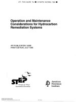
A typical horizontal tank is shown in Figure 1.
Key
1 Welding lines
2
3
Tangent line
Hemispherical head
4
5
Cylindrical courses
Torispherical head
Figure 1 — Typical horizontal tank
4 Petroleum Institute
Copyright American
Reproduced by IHS under license with API
No reproduction or networking permitted without license from IHS
4
--`,,,`,,,`,``,,```,````,,,``-`-`,,`,,`,`,,`---
Licensee=Ecopetrol/5915281003
Not for Resale, 07/01/2005 14:26:21 MDT
© ISO 2002 – All rights reserved
ISO 12917-2:2002(E)
API MPMS 2.2F / ISO 12917-2
8.2
Location of target points — General principle
Target points shall be located on each surface, randomly but distributed over the entire surface. No target points
shall be positioned within 300 mm of a welded seam or stiffener.
NOTE
8.3
It is not a requirement of this method that any particular point be used as a target point
Cylindrical courses
A minimum of 16 target points per course in tanks of diameter less than 3 m, and a minimum of 24 target points per
course in tanks of diameter 3 m or greater, shall be sighted. The uncertainty of calibration will be reduced if the
number of target points is greater than the minimum specified.
8.4
Heads
8.4.1
Flat end, elliptical, spherical head, conical head
A minimum of 50 target points, randomly but evenly distributed over the surface, shall be sighted. The uncertainty
of the calibration will be reduced if a greater number of target points is used.
8.4.2
Knuckle-dished end (head)
A minimum of 16 target points, randomly but evenly distributed over the surface, shall be sighted. The uncertainty
of the calibration will be reduced if a greater number of target points is used.
9
Procedure for calibration
9.1 Measure and record the horizontal angle, the vertical angle and the slope distance to each reference target
point. Two successive readings, at each point, shall be taken and they shall agree within the tolerance given in
clause 10. Compute and record the average angles and distance to each point.
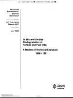
9.2 Measure the horizontal and vertical angles and the slope distance to each target point on a surface. See
Figure 2.
9.3 If more than one measurement station is required, move the instrument from station to station, taking
sufficient measurements at each station to ensure a proper traverse.
9.4 After all measurements from one measurement station are completed, repeat the measurements to the
reference target points.
9.5 If the repeated horizontal and vertical angles and slope distances to each reference target point do not agree
with the measurements taken in 9.1, within the tolerances given in clause 10, determine the reasons for such
disagreement, eliminate the cause and repeat the calibration procedure.
9.6
Commence measurements at one head and progress through the tank to the other head.
9.7
Carry out all measurements without interruption.
10 Tolerances of reference target points
10.1 Distance verification
From each measurement station, the slope distance to each reference target point at the beginning and end of the
calibration shall be within ± 2 mm.
--`,,,`,,,`,``,,```,````,,,``-`-`,,`,,`,`,,`---
5
5
© ISO
2002
– All rights reserved
Copyright American
Petroleum
Institute
Reproduced by IHS under license with API
No reproduction or networking permitted without license from IHS
Licensee=Ecopetrol/5915281003
Not for Resale, 07/01/2005 14:26:21 MDT
ISO 12917-2:2002(E)
API MPMS 2.2F / ISO 12917-2
Dimensions in millimeters
2
3
Reference-gauge position
Course length
4
5
Target point
Torispherical head
6
7
Instrument
Hemispherical head
θ
φ
Horizontal angle
Vertical angle
D
L
Slope distance
Cylindrical length
--`,,,`,,,`,``,,```,````,,,``-`-`,,`,,`,`,,`---
Key
1 Total length (inside)
L1 Length of torospherical head
L2 Length of hemispherical head
Figure 2 — Illustration of calibration procedure
10.2 Verification of horizontal and vertical angles
From each measurement station, the horizontal and vertical angles to each reference target point at the beginning
and end of the calibration shall be within ± 0,010 gon.
11 Additional measurements
11.1 Reference-height determination and reference-point position
The overall height of the reference point at each dip-hatch (upper reference point), if fitted, above the dip-point shall
be measured using a dip tape and weight, as specified in ISO 7507-1. This overall height, to the nearest millimetre,
shall be recorded in the calibration certificate and permanently marked on the tank adjacent to that dip-hatch.
6 Petroleum Institute
Copyright American
Reproduced by IHS under license with API
No reproduction or networking permitted without license from IHS
6
© ISO 2002 – All rights reserved
Licensee=Ecopetrol/5915281003
Not for Resale, 07/01/2005 14:26:21 MDT
ISO 12917-2:2002(E)
API MPMS 2.2F / ISO 12917-2
11.2 Data
The following data shall be determined and processed:
a)
the operating temperature of the liquid to be stored in the tank;
b)
the operating pressure of the tank;
c)
safe filling height and maximum filling height;
d)
deadwood.
11.3 Drawings
If tank construction drawings are available, calibration measurements shall be compared with the corresponding
dimensions shown in these drawings. Any measurements which show significant discrepancies shall be checked.
--`,,,`,,,`,``,,```,````,,,``-`-`,,`,,`,`,,`---
If the calibration and drawing measurements do not agree, the reasons for the discrepancy shall be determined
and the calibration procedure repeated, if necessary.
12 Calculation and development of capacity tables
12.1 Compute the data which describe, in mathematical terms, each surface. Ensure that the various sets of data
for each surface are coherent and describe the tank. (see ISO 7507-4:1995, annex B).
12.2 The development of the capacity table shall be carried out in accordance with ISO 12917-1. The following
corrections, as described in ISO 12917-1, shall be applied in the development of the capacity tables:
a)
correction to the certified tank-shell temperature;
b)
correction to the certified tank-shell pressure;
c)
correction for deadwood;
d)
correction for slope.
7
7
© ISO
2002
– All rights reserved
Copyright American
Petroleum
Institute
Reproduced by IHS under license with API
No reproduction or networking permitted without license from IHS
Licensee=Ecopetrol/5915281003
Not for Resale, 07/01/2005 14:26:21 MDT
ISO 12917-2:2002(E)
API MPMS 2.2F / ISO 12917-2
Annex A
(normative)
Determination of the limiting angle of incidence
A.1
Set up a stadia of 2 m ± 1 mm (this can be undertaken in the laboratory).
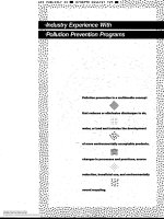
A.3
Mount the stadia on a floor or in a tank as indicated in Figure A.1 and level the stadia.
A.4
Mount the tripod with EODR, as illustrated in Figure A.1.
A.5
For a given distance, D, establish coordinates of target points A and B on the reference bar.
A.6
Compute the distance AB from EODR instruments.
A.7
The maximum variation between the value of AB computed in A.6 and 2 m shall be ± 3 mm.
A.8 Increase the distance D, remeasure the angles to the fixed points A and B on the stadia. Compute the
distance AB using the remeasured angles. Continue this procedure until the variation between the computed value
of AB and the standard length of the stadia exceeds ± 3 mm. Note the smaller angle, of the two measured, and
record it as the limiting angle of incidence.
Key
1 Stadia
2
EODR
Figure A.1 — Test set up
8 Petroleum Institute
Copyright American
Reproduced by IHS under license with API
No reproduction or networking permitted without license from IHS
8
© ISO 2002 – All rights reserved
Licensee=Ecopetrol/5915281003
Not for Resale, 07/01/2005 14:26:21 MDT
--`,,,`,,,`,``,,```,````,,,``-`-`,,`,,`,`,,`---
A.2 The stadia may be temperature compensated to maintain a distance of 2 m automatically by external
compensation or may be compensated manually.
ISO 12917-2:2002(E)
API MPMS 2.2F / ISO 12917-2
Annex B
(informative)
Numerical example
θ and φ are illustrated in Figure 2. D is defined in 3.2 (θ and φ are in gons, D is in millimetres).
NOTE
B.1 Target points on the cylinder
Course numbers 1 to 9 are given in Tables B.1 to B.9.
Table B.1 — Course No. 1
Target
points
θ
φ
Table B.2 — Course No. 2
D
Target
points
θ
φ
D
1
196,010 5
110,262 0
11,118
1
195,002 0
111,587 0
9,724
2
201,895 0
106,007 0
11,373
2
202,440 0
107,615 0
9,758
3
203,321 5
101,245 0
11,549
3
204,910 5
100,405 0
9,754
4
199,962 5
93,552 0
11,377
4
201,035 0
92,442 0
9,890
5
194,353 5
91,295 0
11,352
5
196,301 5
90,095 0
9,920
6
187,331 0
93,830 0
11,423
6
185,071 5
93,592 0
9,740
7
184,172 0
101,000 0
11,453
7
182,572 5
100,207 0
9,814
8
186,851 5
107,517 0
11,365
8
185,352 5
108,105 0
9,760
9
195,271 5
110,960 0
10,388
9
193,199 5
112,950 0
8,508
10
202,547 0
106,280 0
10,530
10
203,889 0
107,892 0
8,688
11
204,392 0
100,850 0
10,302
11
206,239 0
100,180 0
8,699
12
201,520 5
93,632 0
10,333
12
202,354 5
91,520 0
8,703
13
194,226 5
90,380 0
10,440
13
194,041 5
87,712 0
8,472
14
186,282 0
93,267 0
10,331
14
184,221 0
92,332 0
8,700
15
183,152 0
100,342 0
10,356
15
181,086 0
99,220 0
8,666
16
184,921 5
106,497 0
10,363
16
182,046 0
106,390 0
8,439
--`,,,`,,,`,``,,```,````,,,``-`-`,,`,,`,`,,`---
9
9
© ISO
2002
– All rights reserved
Copyright American
Petroleum
Institute
Reproduced by IHS under license with API
No reproduction or networking permitted without license from IHS
Licensee=Ecopetrol/5915281003
Not for Resale, 07/01/2005 14:26:21 MDT
ISO 12917-2:2002(E)
API MPMS 2.2F / ISO 12917-2
Table B.3 — Course No. 3
Target
points
θ
φ
Table B.4 — Course No. 4
D
Target
points
θ
φ
D
1
193,351 5
113,705 0
7,942
1
192,828 5
116,792 0
6,293
2
204,112 5
109,335 0
8,026
2
208,300 5
109,240 0
6,334
3
207,331 5
100,890 0
8,076
3
210,623 0
98,077 0
6,425
4
203,935 0
91,482 0
8,011
4
205,500 0
87,675 0
6,416
5
194,431 5
86,827 0
8,002
5
194,440 0
82,960 0
6,406
6
182,230 0
92,820 0
8,002
6
178,963 5
90,765 0
6,358
7
179,808 5
98,662 0
7,900
7
175,854 0
99,290 0
6,315
8
182,829 5
109,145 0
7,851
8
178,279 5
108,547 0
6,312
9
193,449 0
115,725 0
6,782
9
192,586 0
120,827 0
5,010
10
207,259 0
108,630 0
6,828
10
212,160 5
111,107 0
5,045
11
209,639 0
99,165 0
6,856
11
215,411 5
97,767 0
5,042
12
205,942 0
89,980 0
6,843
12
207,221 0
82,820 0
5,118
13
194,401 5
84,000 0
6,762
13
193,545 5
78,045 0
5,135
14
179,568 0
92,382 0
6,840
14
175,354 5
88,517 0
5,208
15
177,326 5
99,012 0
6,814
15
171,318 5
99,640 0
5,098
16
181,362 0
110,622 0
6,776
16
173,769 0
109,090 0
5,108
Table B.5 — Course No. 5
Target
points
θ
φ
Table B.6 — Course No. 6
D
Target
points
θ
φ
D
1
192,041 0
123,362 0
4,438
1
193,861 5
135,665 0
2,914
2
214,493 5
111,757 0
4,541
2
227,810 5
116,255 0
2,907
3
217,165 5
98,845 0
4,693
3
231,322 5
97,847 0
3,005
4
214,871 5
88,687 0
4,663
4
219,733 0
72,112 0
3,123
5
193,458 5
75,457 0
4,664
5
193,835 0
61,947 0
3,211
6
176,063 0
82,675 0
4,652
6
166,483 0
70,700 0
3,103
7
168,951 0
97,505 0
4,630
7
155,196 0
99,190 0
3,106
8
171,354 0
109,627 0
4,613
8
160,048 0
115,762 0
3,078
9
192,200 0
129,992 0
3,444
9
191,506 0
154,790 0
2,012
10
222,179 0
113,145 0
3,474
10
246,433 5
120,092 0
2,094
11
225,482 0
97,632 0
3,519
11
252,512 5
89,502 0
2,106
12
221,152 5
82,230 0
3,540
12
237,006 5
54,565 0
2,203
13
193,436 5
66,610 0
3,570
13
193,771 5
41,232 0
2,311
14
166,536 5
80,385 0
3,564
14
151,061 0
58,310 0
2,336
15
160,495 5
96,290 0
3,538
15
133,682 0
91,362 0
2,198
16
163,738 5
113,445 0
3,447
16
144,662 5
133,652 0
2,064
10 Petroleum Institute
Copyright American
Reproduced by IHS under license with API
No reproduction or networking permitted without license from IHS
10
--`,,,`,,,`,``,,```,````,,,``-`-`,,`,,`,`,,`---
© ISO 2002 – All rights reserved
Licensee=Ecopetrol/5915281003
Not for Resale, 07/01/2005 14:26:21 MDT
ISO 12917-2:2002(E)
API MPMS 2.2F / ISO 12917-2
Target
points
θ
φ
Table B.8 — Course No. 8
D
Target
points
θ
φ
D
1
242,361 0
159,810 0
1,675
1
396,611 5
159,882 0
1,806
2
267,218 0
121,435 0
1,724
2
332,431 5
122,225 0
1,844
3
269,530 0
90,347 0
1,801
3
328,588 0
90,367 0
1,954
4
254,902 0
47,412 0
1,940
4
336,892 0
52,072 0
2,049
5
190,475 0
27,155 0
2,042
5
399,042 0
29,242 0
2,134
6
128,496 0
54,002 0
2,004
6
55,105 0
58,467 0
2,105
7
119,625 5
86,880 0
1,940
7
61,739 0
89,090 0
2,042
8
121,601 5
121,847 0
1,843
8
56,296 0
121,612 0
1,947
9
338,683 5
159,897 0
1,592
9
394,874 5
134,455 0
2,737
10
307,674 0
123,877 0
1,605
10
357,833 0
113,920 0
2,711
11
311,701 0
89,462 0
1,742
11
353,185 5
93,965 0
2,776
12
316,502 5
54,352 0
1,842
12
362,599 5
67,345 0
2,872
13
5,369 5
15,542 0
1,954
13
396,503 5
53,960 0
2,946
14
71,005 0
51,020 0
1,940
14
28,066 5
68,347 0
2,911
15
77,312 0
89,960 0
1,847
15
35,283 5
88,780 0
2,923
16
73,181 0
122,107 0
1,757
16
29,811 5
116,112 0
2,816
Table B.9 — Course No. 9
Target
points
θ
φ
D
1
394,872 0
128,472 0
3,221
2
366,098 5
113,905 0
3,222
3
360,109 5
93,652 0
3,267
4
365,204 0
76,047 0
3,317
5
2,771 0
60,240 0
3,306
6
21,629 5
71,915 0
3,373
7
29,201 5
95,825 0
3,352
8
23,255 0
114,512 0
3,277
9
395,381 5
120,805 0
4,263
10
374,734 5
110,675 0
4,383
11
369,298 5
97,842 0
4,339
12
374,196 0
80,712 0
4,453
13
394,500 0
71,117 0
4,589
14
12,045 0
77,647 0
4,542
15
20,053 0
95,395 0
4,416
16
13,752 0
111,467 0
4,453
11
11
© ISO
2002
– All rights reserved
Copyright American
Petroleum
Institute
Reproduced by IHS under license with API
No reproduction or networking permitted without license from IHS
--`,,,`,,,`,``,,```,````,,,``-`-`,,`,,`,`,,`---
Table B.7 — Course No. 7
Licensee=Ecopetrol/5915281003
Not for Resale, 07/01/2005 14:26:21 MDT
ISO 12917-2:2002(E)
API MPMS 2.2F / ISO 12917-2
B.2 Target points on the first torispherical head
Tables B.10 and B.11 give values for the spherical portion and torical junction, respectively.
Table B.10 — Spherical portion (first
torispherical head)
Target
points
θ
φ
Table B.11 — Torical junction (first
torispherical head)
D
Target
points
θ
φ
D
1
194,340 0
93,522 0
11,986
1
194,889 0
109,590 0
11,835
2
194,292 0
97,350 0
12,125
2
201,386 5
105,450 0
11,829
3
194,292 0
100,412 0
12,156
3
202,442 5
100,982 0
11,862
4
194,649 5
104,507 0
12,112
4
200,282 5
95,085 0
11,872
5
195,353 5
107,890 0
11,976
5
194,215 0
92,100 0
11,860
6
197,256 0
100,362 0
12,130
6
188,083 5
94,410 0
11,886
7
200,704 0
100,362 0
11,993
7
185,076 0
100,215 0
11,858
8
189,961 5
100,402 0
12,122
8
186,002 5
105,200 0
11,828
9
185,887 0
100,402 0
11,952
10
187,211 5
105,522 0
11,943
11
199,689 5
105,522 0
11,954
12
199,689 5
95,707 0
11,953
13
187,641 0
95,707 0
11,950
14
190,250 0
97,490 0
12,085
15
197,803 0
97,450 0
12,075
16
197,461 5
104,287 0
12,067
17
189,756 0
104,287 0
12,068
--`,,,`,,,`,``,,```,````,,,``-`-`,,`,,`,`,,`---
12 Petroleum Institute
Copyright American
Reproduced by IHS under license with API
No reproduction or networking permitted without license from IHS
12
© ISO 2002 – All rights reserved
Licensee=Ecopetrol/5915281003
Not for Resale, 07/01/2005 14:26:21 MDT
ISO 12917-2:2002(E)
API MPMS 2.2F / ISO 12917-2
B.3 Target points on the second torispherical head
Tables B.12 and B.13 give values for the spherical portion and torical junction, respectively.
Table B.12 — Spherical portion (second
torispherical head)
Target
points
θ
φ
Table B.13 — Torical junction (second
torispherical head)
D
Target
points
θ
φ
D
1
394,802 0
113,782 0
4,901
1
394,453 5
117,260 0
4,820
2
394,361 5
103,330 0
5,000
2
376,245 0
108,347 0
4,804
3
394,361 5
96,377 0
5,017
3
372,033 5
95,727 0
4,803
4
394,362 0
87,402 0
5,015
4
378,122 0
80,330 0
4,857
5
394,361 5
77,460 0
4,990
5
393,942 5
74,785 0
4,946
6
376,668 0
96,770 0
4,939
6
6,910 5
78,022 0
4,928
7
385,471 5
96,487 0
5,005
7
16,463 5
94,855 0
4,870
8
3,620 0
96,572 0
5,000
8
11,913 5
109,372 0
4,829
9
12,029 0
96,887 0
4,956
10
7,386 0
107,410 0
4,926
11
7,386 0
83,757 0
4,988
12
380,381 0
83,757 0
4,969
13
380,381 5
107,557 0
4,909
14
387,851 5
101,970 0
4,994
15
2,632 5
101,972 0
4,991
16
1,520 0
89,762 0
5,014
17
387,739 5
89,562 0
5,012
B.4 Results
B.4.1 Cylinder
Radius:
R = 1,699 m
Axis vector:
Vx = 0,995 2
Vy = 0,093 1
⇒ slope = 0,029 9
Vz = 0,029 9
Length:
L = 15,881 m
B.4.2 First torispherical head
Torus radius:
r1 = 0,361 m
Sphere radius:
R1 = 3,677 m
Head lengths:
L1 = 0,643 m
13
--`,,,`,,,`,``,,```,````,,,``-`-`,,`,,`,`,,`---
13
© ISO
2002
– All rights reserved
Copyright American
Petroleum
Institute
Reproduced by IHS under license with API
No reproduction or networking permitted without license from IHS
Licensee=Ecopetrol/5915281003
Not for Resale, 07/01/2005 14:26:21 MDT
ISO 12917-2:2002(E)
API MPMS 2.2F / ISO 12917-2
B.4.3 Second torispherical head
Torus radius:
r2 = 0,382 m
Sphere radius:
R2 = 3,657 m
Head length:
L2 = 0,659 m
Total length = L1 + L + L2 = 17,183 m
14 Petroleum Institute
Copyright American
Reproduced by IHS under license with API
No reproduction or networking permitted without license from IHS
14
--`,,,`,,,`,``,,```,````,,,``-`-`,,`,,`,`,,`---
Licensee=Ecopetrol/5915281003
Not for Resale, 07/01/2005 14:26:21 MDT
© ISO 2002 – All rights reserved