Bsi bs 4a 169 2002 (2006)
Bạn đang xem bản rút gọn của tài liệu. Xem và tải ngay bản đầy đủ của tài liệu tại đây (600.8 KB, 20 trang )
BRITISH STANDARD AEROSPACE SERIES
Specification for
aluminium alloy bolts
(Unified hexagons and
Unified threads) for
aircraft
ICS 49. 030. 20
BS 4A 169:2002
Amendment No. 1
BS 4A 169:2002
Committees responsible for this
British Standard
The preparation of this British Standard was entrusted to Technical
Committee ACE/1 2, Aerospace fasteners and fastening, upon which the
following bodies were represented:
Civil Aviation Authority (Airworthiness Division)
Confederation of British Forgers
Institute of Petroleum
Ministry of Defence
Society of British Aerospace Companies Ltd.
This British Standard, having
been prepared under the
direction of the Engineering
Sector Policy and Strategy
Committee, was published
under the authority of the
Standards Policy and Strategy
Committee on 28 January 2002
© BSI 2006
The following BSI references
relate to the work on this
standard:
Committee reference ACE/12
Draft for comment 00/704897 DC
ISBN 0 580 33292 6
Amendments issued since publication
Amd. No.
Date
Comments
1 6376
June 2006
Corrections to Table 2.
BS 4A 169:2002
Contents
Page
Committees responsible
Inside front cover
Foreword
ii
1
Scope
1
2
Normative references
1
3
General requirements
1
4
Materials and manufacture
1
5
Dimensions and tolerances
1
6
Screw threads
1
7
Anti-corrosion treatment
1
8
Hardness values
1
9
Identification and marking
1
10
Quality assurance procedure
1
Bibliography
15
Table 1 — Dimensions of bolts
3
Table 2 — Bearing length
5
L, clamping length M and overall length E
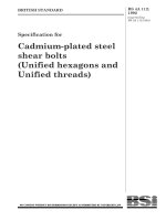
Figure 1 — Dimensions of bolts (see Table 1)
Figure 2 — Bearing length
(see Table 2)
© BSI 200 6
L, clamping length M and overall length E
2
4
i
BS 4A 169:2002
Foreword
This British Standard has been prepared by Technical Committee ACE/1 2. It is a
revision of BS 3A 169: 1 962 which is superseded and withdrawn.
This revision of BS 3A 1 69 refers to the relevant requirements in BS A 100. It
incorporates amendment 1 of BS 3A 169 and updates and revises material
specifications.
NOTE
Fasteners manufactured to previous editions of this specification may continue to be supplied
until stocks are exhausted.
A British Standard does not purport to include all the necessary provisions of a
contract. Users of British Standards are responsible for their correct application.
Compliance with a British Standard does not of itself confer immunity
from legal obligations.
Summary of pages
This document comprises a front cover, and inside front cover, pages i and ii,
pages 1 to 1 5 and a back cover.
The BSI copyright notice displayed in this document indicates when the
document was last issued.
ii
© BSI 2 00 6
BS 4A 169:2002
1 Scope
This British Standard specifies materials and manufacture, dimensions, protective treatment and quality
assurance requirements for aluminium-alloy hexagon-head bolts with unified threads.
NOTE The latest edition of an Aerospace Series standard is indicated by a prefix number.
2 Normative references
The following normative documents contain provisions which, through reference in this text, constitute
provisions of this British Standard. For dated references, subsequent amendments to, or revisions of, any
of these publications do not apply. For undated references, the latest edition of the publication referred to
applies.
BS 3A 100, Specification for general requirements for bolts and free-running nuts of tensile strength not
exceeding 1 249 MPa.
BS L 1 68, Specification for bars and extruded sections of aluminium-copper-magnesium-silicon-manganese
alloy (solution treated and artificially aged) (not exceeding 200 mm diameter or minor sectional dimension)
(Cu 4.4, Mg 0.5, Si 0.7, Mn 0.8).
3 General requirements
Bolts shall conform to BS A 1 00.
4 Materials and manufacture
The bolts shall be machined from bars that conform to BS L 1 68.
5 Dimensions and tolerances
5.1 All finished bolts shall conform to the dimensions and tolerances specified in Table 1 and Table 2.
5.2 The clamping length of the bolt shall conform to the dimensions and tolerances specified in Table 2, and
shall be such that when a standard nut, without countersink or ring gauge is, screwed on as far as possible
by hand, its leading face is within a distance
from the underside of the bolt head. The run-out of the
M
thread shall not exceed twice the thread pitch.
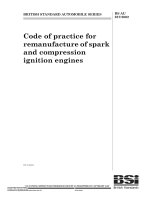
5.3 The nominal length of the bolt shall be the minimum bearing length L, which is determined by the
minimum clamping length,
M, less two thread pitches (see Table 2).
L quoted in Table 2 are in 0. 1 0 inch increments but where a 0. 05 length increment is required this should
be by agreement between manufacturer and user and should be identified as follows: 8 ? B, indicating a 6-32 UNC bolt of bearing
length L 0. 85 inches. M and E need to be adj usted accordingly.
NOTE The bearing lengths
?
6 Screw threads
The bolts shall have unified screw threads, of the form and fit specified in the latest edition of BS A 1 00.
7 Anti-corrosion treatment
All finished bolts shall be anodized and dyed green.
NOTE Because of the use of the chromic acid process for anodizing, the bolts will not necessarily be uniformly coloured after staining.
8 Hardness values
NOTE Hardness values are not currently applicable, though they may become applicable in the near future.
9 Identification and marking
The bolts shall be marked in accordance with BS 3A 1 00: 1 991 , clause
10 Quality assurance procedure
8.
The bolts shall conform to the quality requirements specified in BS A 1 00, as appropriate to the method of
manufacture.
© BSI 200 6
1
BS 4A 169:2002
2
D
B
D
M ax. ru n o u t o f
L*
R
th re ad = 2 x p i tch
( b e ari n g le n g th )
F
1 5º
R
D i a. o f wash e r
( fo r re f.
rad .
0
face = B m i n .
o n ly)
A
C
rad .
45 º
30º
0.01 5 i n
G
M*
( clam p i n g le n g th )
3 0º
E*
( o ve rall le n g th )
a)
b)
© BSI 200 6
Figure 1 — Dimensions of bolts (see Table 1 )
- 0.01
in
© BSI 20 06
Table 1 — Dimensions of bolts
1
Nominal size
2
3
4
5
6
7
8
9
Decimal
2?
Diameter of
Min. Width across flats Width
equivalent plain portion of pitch length of
across
of nominal
screwed
shank
corners
portion
size
of shank
A
in
?
??
?
??
?
??
???
F?
max.
min.
in
in
Ref. only
in
in
B
max.
in
10
11
12
13
Thickness of head Radius under bolt
heat
C
min.
in
max.
D
max.
14
15
Depth of
chamfer
R
min.
max.
G
min.
in
max.
min.
in
in
in
in
0. 1 1 2-40 UNC (4)
0. 11 20
0. 1 1 1 5 0. 1 085 0. 050
0. 300
0. 1 88
0. 1 83
0. 21 7
0. 070
0. 060
0. 01 5
0. 005
0. 020
in
0. 01 5
in
0. 1 38-32 UNC (6)
0. 1380
0. 1 375 0. 1 345 0. 063
0. 277
0. 250
0. 245
0. 289
0. 085
0. 075
0. 01 5
0. 005
0. 030
0. 020
0. 1 64-32 UNC (8)
0. 1640
0. 1 635 0. 1 605 0. 063
0. 327
0. 31 2
0. 307
0. 361
0. 1 00
0. 090
0. 020
0. 01 0
0. 030
0. 020
0. 1 90-32 UNF (1 0)
0. 1900
0. 1 895 0. 1 865 0. 063
0. 377
0. 344
0. 339
0. 397
0. 1 15
0. 1 05
0. 020
0. 01 0
0. 030
0. 020
0. 250-28 UNF (E)
0. 2500
0. 2495 0. 2465 0. 071
0. 459
0. 438
0. 431
0. 505
0. 1 50
0. 1 40
0. 030
0. 01 5
0. 040
0. 030
0. 31 25-24 UNF (G)
0. 31 25
0. 31 20 0. 3090 0. 083
0. 497
0. 500
0. 493
0. 577
0. 1 80
0. 1 70
0. 030
0. 01 5
0. 040
0. 030
0. 375-24 UNF (J)
0. 3750
0. 3745 0. 3715 0. 083
0. 597
0. 562
0. 554
0. 650
0. 220
0. 210
0. 030
0. 01 5
0. 040
0. 030
0. 4375-20 UNF (L)
0. 4375
0. 4370 0. 4335 0. 1 00
0. 670
0. 688
0. 679
0. 794
0. 270
0. 260
0. 030
0. 01 5
0. 050
0. 040
0. 500-20 UNF (N)
0. 5000
0. 4995 0. 4960 0. 1 00
0. 770
0. 750
0. 741
0. 866
0. 300
0. 290
0. 030
0. 01 5
0. 050
0. 040
0. 5625-1 8 UNF (P)
0. 5625
0. 5620 0. 5585 0. 1 1 1
0. 859
0. 875
0. 866
1 . 01 0
0. 350
0. 340
0. 030
0. 01 5
0. 050
0. 040
0. 625-1 8 UNF (Q)
0. 6250
0. 6245 0. 6205 0. 1 1 1
0. 949
0. 938
0. 929
1 . 083
0. 390
0. 380
0. 030
0. 01 5
0. 060
0. 050
* For bearing length
L, clampling length M and overall length E see Table 2.
? This dimension is an absolute minimum associated with maximum length
??
M and minimum length E. It is not intended for use for manufacturing or inspection purposes.
?
BS 4A 169:2002
3
4
b)
E
Figure 2 — Bearing length L, clamping length M and overall length E (see Table 2)
a)
M
M
E
L
L
BS 4A 169:2002
© BSI 200 6
© BSI 200 6
Table 2 — Bearing length L, clamping length M and overall length E
No. 4-40 UNC
Part No.
L*
min.
in
M
+0
– 0.03
in
No. 6-32 UNC
E
Part No.
L*
min.
+ 0.04
–0
in
?A
0. 05
0. 1 30
0. 45
1A
0. 1
0. 1 80
0. 50
2A
0. 2
0. 280
3A
0. 3
4A
in
M
+0
– 0. 03
in
No. 8-32 UNC
E
Part No.
L*
min.
+ 0.04
–0
in
?B
0. 05
0. 1 43
0. 45
1B
0. 1
0. 1 93
0. 50
0. 60
2B
0. 2
0. 293
0. 60
0. 380
0. 70
3B
0. 3
0. 393
0. 4
0. 480
0. 80
4B
0. 4
5A
0. 5
0. 580
0. 90
5B
6A
0. 6
0. 680
1 . 00
7A
0. 7
0. 780
1.10
8A
0. 8
0. 880
9A
0. 9
1 0A
1. 0
?C
in
M
+0
– 0.03
in
No. 10-32 UNF
E
Part No.
L*
min.
+ 0.04
–0
in
0. 05
0. 1 43
0. 50
1C
0. 1
0. 193
0. 55
2C
0. 2
0. 293
0. 65
0. 70
3C
0. 3
0. 393
0. 493
0. 80
4C
0. 4
0. 5
0. 593
0. 90
5C
6B
0. 6
0. 693
1 . 00
7B
0. 7
0. 793
1.10
1 . 20
8B
0. 8
0. 893
0. 980
1 . 30
9B
0. 9
1. 080
1 . 40
10B
1.0
?D
in
M
+0
–0.03
in
E
+ 0.04
–0
in
0. 05
0. 1 43
0. 55
1D
0. 1
0. 1 93
0. 60
2D
0. 2
0. 293
0. 70
0. 75
3D
0. 3
0. 393
0. 80
0. 493
0. 85
4D
0. 4
0. 493
0. 90
0. 5
0. 593
0. 95
5D
0. 5
0. 593
1 . 00
6C
0. 6
0. 693
1 . 05
6D
0. 6
0. 693
1.10
7C
0. 7
0. 793
1.15
7D
0. 7
0. 793
1 . 20
1 . 20
8C
0. 8
0. 893
1 . 25
8D
0. 8
0. 893
1 . 30
0. 993
1 . 30
9C
0. 9
0. 993
1 . 35
9D
0. 9
0. 993
1 . 40
1 . 093
1 . 40
1 0C
1.0
1 . 093
1 . 45
1 0D
1.0
1 . 093
1 . 50
11A
1. 1
1. 1 80
1 . 50
11 B
1.1
1 . 1 93
1 . 50
11C
1.1
1 . 1 93
1 . 55
1 1D
1.1
1 . 1 93
1 . 60
1 2A
1. 2
1. 280
1 . 60
12B
1.2
1 . 293
1 . 60
1 2C
1.2
1 . 293
1 . 65
1 2D
1.2
1 . 293
1 . 70
1 3A
1. 3
1. 380
1 . 70
13B
1.3
1 . 393
1 . 70
1 3C
1.3
1 . 393
1 . 75
1 3D
1.3
1 . 393
1 . 80
1 4A
1. 4
1. 480
1 . 80
14B
1.4
1 . 493
1 . 80
1 4C
1.4
1 . 493
1 . 85
1 4D
1.4
1 . 493
1 . 90
1 5A
1. 5
1. 580
1 . 90
15B
1.5
1 . 593
1 . 90
1 5C
1.5
1 . 593
1 . 95
1 5D
1.5
1 . 593
2. 00
1 6A
1. 6
1. 680
2. 00
16B
1.6
1 . 693
2. 00
1 6C
1.6
1 . 693
2. 05
1 6D
1.6
1 . 693
2. 10
1 7A
1. 7
1. 780
2. 1 0
17B
1.7
1 . 793
2. 1 0
1 7C
1.7
1 . 793
2. 1 5
1 7D
1.7
1 . 793
2. 20
1 8A
1. 8
1. 880
2. 20
18B
1.8
1 . 893
2. 20
1 8C
1.8
1 . 893
2. 25
1 8D
1.8
1 . 893
2. 30
1 9A
1. 9
1. 980
2. 30
19B
1.9
1 . 993
2. 30
1 9C
1.9
1 . 993
2. 35
1 9D
1.9
1 . 993
2. 40
20A
2. 0
2. 080
2. 40
20B
2. 0
2. 093
2. 40
20C
2. 0
2. 093
2. 45
20D
2. 0
2. 093
2. 50
*
See
5.3 .
BS 4A 169:2002
5
No. 4-40 UNC
Part No.
L*
min.
in
21 A
2. 1
No. 6-32 UNC
M
+0
– 0.03
in
2. 1 80
E
Part No.
L*
min.
+ 0.04
–0
in
2. 50
in
21 B
2. 1
M
+0
– 0. 03
in
2. 1 93
No. 8-32 UNC
E
Part No.
L*
min.
+ 0.04
–0
in
2. 50
in
21 C
2. 1
M
+0
– 0.03
in
2. 1 93
No. 10-32 UNF
E
Part No.
L*
min.
+ 0.04
–0
in
2. 55
in
21D
2. 1
M
+0
–0.03
in
2. 1 93
E
+ 0.04
–0
in
2. 60
22A
2. 2
2. 280
2. 60
22B
2. 2
2. 293
2. 60
22C
2. 2
2. 293
2. 65
22D
2. 2
2. 293
2. 70
23A
2. 3
2. 380
2. 70
23B
2. 3
2. 393
2. 70
23C
2. 3
2. 393
2. 75
23D
2. 3
2. 393
2. 80
24A
2. 4
2. 480
2. 80
24B
2. 4
2. 493
2. 80
24C
2. 4
2. 493
2. 85
24D
2. 4
2. 493
2. 90
25A
2. 5
2. 580
2. 90
25B
2. 5
2. 593
2. 90
25C
2. 5
2. 593
2. 95
25D
2. 5
2. 593
3. 00
26A
2. 6
2. 680
3. 00
26B
2. 6
2. 693
3. 00
26C
2. 6
2. 693
3. 05
26D
2. 6
2. 693
3. 1 0
27A
2. 7
2. 780
3. 1 0
27B
2. 7
2. 793
3. 1 0
27C
2. 7
2. 793
3. 1 5
27D
2. 7
2. 793
3. 20
28B
2. 8
2. 893
3. 20
28C
2. 8
2. 893
3. 25
28D
2. 8
2. 893
3. 30
*
See
5.3 .
BS 4A 169:2002
6
Table 2 — Bearing length L, clamping length M and overall length (continued)
© BSI 200 6
BS 4A 169:2002
Table 2 — Bearing length L, clamping length M and overall length E (continued)
No. 6-32 UNC
Part No.
L*
min.
in
M
+0
– 0.03
in
No. 8-32 UNC
E
Part No.
L*
+ 0.04
–0
min.
in
in
M
+0
– 0.03
in
No. 10-32 UNC
E
Part No.
L*
+ 0.04
–0
min.
in
in
M
+0
– 0. 03
in
E
+ 0.04
–0
in
29B
2. 9
2. 993
3. 30
29C
2. 9
2. 993
3. 35
29D
2. 9
2. 993
3. 40
30B
3. 0
3. 093
3. 40
30C
3. 0
3. 093
3. 45
30D
3. 0
3. 093
3. 50
31B
3. 1
3. 1 93
3. 50
31C
3. 1
3. 1 93
3. 55
31 D
3. 1
3. 193
3. 60
32B
3. 2
3. 293
3. 60
32C
3. 2
3. 293
3. 65
32D
3. 2
3. 293
3. 70
33B
3. 3
3. 393
3. 70
33C
3. 3
3. 393
3. 75
33D
3. 3
3. 393
3. 80
34B
3. 4
3. 493
3. 80
34C
3. 4
3. 493
3. 85
34D
3. 4
3. 493
3. 90
35B
3. 5
3. 593
3. 90
35C
3. 5
3. 593
3. 95
35D
3. 5
3. 593
4. 00
36B
3. 6
3. 693
4. 00
36C
3. 6
3. 693
4. 05
36D
3. 6
3. 693
4. 1 0
37B
3. 7
3. 793
4. 1 0
37C
3. 7
3. 793
4. 1 5
37D
3. 7
3. 793
4. 20
38B
3. 8
3. 893
4. 20
38C
3. 8
3. 893
4. 25
38D
3. 8
3. 893
4. 30
39B
3. 9
3. 993
4. 30
39C
3. 9
3. 993
4. 35
39D
3. 9
3. 993
4. 40
40B
4. 0
4. 093
4. 40
40C
4. 0
4. 093
4. 45
40D
4. 0
4. 093
4. 50
41B
4. 1
4. 1 93
4. 50
41C
4. 1
4. 1 93
4. 55
41 D
4. 1
4. 193
4. 60
42B
4. 2
4. 293
4. 60
42C
4. 2
4. 293
4. 65
42D
4. 2
4. 293
4. 70
43B
4. 3
4. 393
4. 70
43C
4. 3
4. 393
4. 75
43D
4. 3
4. 393
4. 80
44B
4. 4
4. 493
4. 80
44C
4. 4
4. 493
4. 85
44D
4. 4
4. 493
4. 90
45B
4. 5
4. 593
4. 90
45C
4. 5
4. 593
4. 95
45D
4. 5
4. 593
5. 00
46B
4. 6
4. 693
5. 00
46C
4. 6
4. 693
5. 05
46D
4. 6
4. 693
5. 1 0
47B
4. 7
4. 793
5. 1 0
47C
4. 7
4. 793
5. 1 5
47D
4. 7
4. 793
5. 20
48B
4. 8
4. 893
5. 20
48C
4. 8
4. 893
5. 25
48D
4. 8
4. 893
5. 30
49B
4. 9
4. 993
5. 30
49C
4. 9
4. 993
5. 35
49D
4. 9
4. 993
5. 40
50B
5. 0
5. 093
5. 40
50C
5. 0
5. 093
5. 45
50D
5. 0
5. 093
5. 50
51B
5. 1
5. 1 93
5. 50
51C
5. 1
5. 1 93
5. 55
51 D
5. 1
5. 193
5. 60
52B
5. 2
5. 293
5. 60
52C
5. 2
5. 293
5. 65
52D
5. 2
5. 293
5. 70
53B
5. 3
5. 393
5. 70
53C
5. 3
5. 393
5. 75
53D
5. 3
5. 393
5. 80
*
See
54D
5. 4
5. 493
5. 90
55D
5. 5
5. 593
6. 00
56D
5. 6
5. 693
6. 1 0
57D
5. 7
5. 793
6. 20
58D
5. 8
5. 893
6. 30
59D
5. 9
5. 993
6. 40
60D
6. 0
6. 093
6. 50
5.3 .
© BSI 200 6
7
BS 4A 169:2002
Part No.
Table 2 — Bearing length L, clamping length M and overall length E (continued)
? in UNF
? in UNF
? in UNF
L*
min.
in
?E
M
+0
– 0.03
in
E
Part No.
+ 0. 04
–0
L*
min.
in
in
M
+0
– 0.03
in
E
Part No.
L*
+ 0.04
–0
min.
in
in
M
+0
– 0.03
in
E
+ 0.04
–0
in
0. 05
0. 1 51
0. 65
½G
0. 05
0. 1 63
0. 70
1E
0. 1
0. 201
0. 70
1G
0. 1
0. 21 3
0. 75
1J
0. 1
0. 21 3
2E
0. 2
0. 301
0. 80
2G
0. 2
0. 31 3
0. 85
2J
0. 2
0. 31 3
0. 95
3E
0. 3
0. 401
0. 90
3G
0. 3
0. 41 3
0. 95
3J
0. 3
0. 41 3
1 . 05
4E
0. 4
0. 501
1 . 00
4G
0. 4
0. 51 3
1 . 05
4J
0. 4
0. 51 3
1.15
5E
0. 5
0. 601
1.10
5G
0. 5
0. 61 3
1.15
5J
0. 5
0. 61 3
1 . 25
6E
0. 6
0. 701
1 . 20
6G
0. 6
0. 71 3
1 . 25
6J
0. 6
0. 71 3
1 . 35
7E
0. 7
0. 801
1 . 30
7G
0. 7
0. 81 3
1 . 35
7J
0. 7
0. 81 3
1 . 45
8E
0. 8
0. 901
1 . 40
8G
0. 8
0. 91 3
1 . 45
8J
0. 8
0. 91 3
1 . 55
9E
0. 9
1. 001
1 . 50
9G
0. 9
1 . 01 3
1 . 55
9J
0. 9
1 . 01 3
1 . 65
1 0E
1.0
1. 1 01
1 . 60
1 0G
1.0
1.113
1 . 65
1 0J
1.0
1.113
1 . 75
0. 85
11E
1.1
1. 201
1 . 70
1 1G
1.1
1 . 21 3
1 . 75
11J
1.1
1 . 21 3
1 . 85
1 2E
1.2
1. 301
1 . 80
1 2G
1.2
1 . 31 3
1 . 85
1 2J
1.2
1 . 31 3
1 . 95
1 3E
1.3
1. 401
1 . 90
1 3G
1.3
1 . 41 3
1 . 95
1 3J
1.3
1 . 41 3
2. 05
1 4E
1.4
1. 501
2. 00
1 4G
1.4
1 . 51 3
2. 05
1 4J
1.4
1 . 51 3
2. 1 5
1 5E
1.5
1. 601
2. 1 0
1 5G
1.5
1 . 61 3
2. 1 5
1 5J
1.5
1 . 61 3
2. 25
1 6E
1.6
1. 701
2. 20
1 6G
1.6
1 . 71 3
2. 25
1 6J
1.6
1 . 71 3
2. 35
1 7E
1.7
1. 801
2. 30
1 7G
1.7
1 . 81 3
2. 35
1 7J
1.7
1 . 81 3
2. 45
1 8E
1.8
1. 901
2. 40
1 8G
1.8
1 . 91 3
2. 45
1 8J
1.8
1 . 91 3
2. 55
1 9E
1.9
2. 001
2. 50
1 9G
1.9
2. 01 3
2. 55
1 9J
1.9
2. 01 3
2. 65
20E
2. 0
2. 1 01
2. 60
20G
2. 0
2. 1 1 3
2. 65
20J
2. 0
2. 1 1 3
2. 75
21 E
2. 1
2. 201
2. 70
21G
2. 1
2. 21 3
2. 75
21 J
2. 1
2. 21 3
2. 85
22E
2. 2
2. 301
2. 80
22G
2. 2
2. 31 3
2. 85
22J
2. 2
2. 31 3
2. 95
23E
2. 3
2. 401
2. 90
23G
2. 3
2. 41 3
2. 95
23J
2. 3
2. 41 3
3. 05
24E
2. 4
2. 501
3. 00
24G
2. 4
2. 51 3
3. 05
24J
2. 4
2. 51 3
3. 1 5
25E
2. 5
2. 601
3. 1 0
25G
2. 5
2. 61 3
3. 1 5
25J
2. 5
2. 61 3
3. 25
26E
2. 6
2. 701
3. 20
26G
2. 6
2. 71 3
3. 25
26J
2. 6
2. 71 3
3. 35
27E
2. 7
2. 801
3. 30
27G
2. 7
2. 81 3
3. 35
27J
2. 7
2. 81 3
3. 45
28E
2. 8
2. 901
3. 40
28G
2. 8
2. 91 3
3. 45
28J
2. 8
2. 91 3
3. 55
29E
2. 9
3. 001
3. 50
29G
2. 9
3. 01 3
3. 55
29J
2. 9
3. 01 3
3. 65
30E
3. 0
3. 1 01
3. 60
30G
3. 0
3. 1 1 3
3. 65
30J
3. 0
3. 1 1 3
3. 75
31 E
3. 1
3. 201
3. 70
31G
3. 1
3. 21 3
3. 75
31 J
3. 1
3. 21 3
3. 85
32E
3. 2
3. 301
3. 80
32G
3. 2
3. 31 3
3. 85
32J
3. 2
3. 31 3
3. 95
33E
3. 3
3. 401
3. 90
33G
3. 3
3. 41 3
3. 95
33J
3. 3
3. 41 3
4. 05
34E
3. 4
3. 501
4. 00
34G
3. 4
3. 51 3
4. 05
34J
3. 4
3. 51 3
4. 1 5
35E
3. 5
3. 601
4. 1 0
35G
3. 5
3. 61 3
4. 1 5
35J
3. 5
3. 61 3
4. 25
*
8
See
5.3 .
© BSI 200 6
BS 4A 169:2002
Part No.
Table 2 — Bearing length L, clamping length M and overall length E (continued)
? in UNF
? in UNF
? in UNF
L*
min.
in
M
+0
– 0.03
in
E
Part No.
+ 0.04
–0
L*
min.
in
in
M
+0
– 0.03
in
E
Part No.
+ 0. 04
–0
L*
min.
in
in
M
+0
– 0. 03
in
E
+ 0.04
–0
in
36E
3. 6
3. 701
4. 20
36G
3. 6
3. 71 3
4. 25
36J
3. 6
3. 71 3
4. 35
37E
3. 7
3. 801
4. 30
37G
3. 7
3. 81 3
4. 35
37J
3. 7
3. 81 3
4. 45
38E
3. 8
3. 901
4. 40
38G
3. 8
3. 91 3
4. 45
38J
3. 8
3. 91 3
4. 55
39E
3. 9
4. 001
4. 50
39G
3. 9
4. 01 3
4. 55
39J
3. 9
4. 01 3
4. 65
40E
4. 0
4. 1 01
4. 60
40G
4. 0
4. 1 1 3
4. 65
40J
4. 0
4. 1 1 3
4. 75
41 E
4. 1
4. 201
4. 70
41 G
4. 1
4. 21 3
4. 75
41 J
4. 1
4. 21 3
4. 85
42E
4. 2
4. 301
4. 80
42G
4. 2
4. 31 3
4. 85
42J
4. 2
4. 31 3
4. 95
43E
4. 3
4. 401
4. 90
43G
4. 3
4. 41 3
4. 95
43J
4. 3
4. 41 3
5. 05
44E
4. 4
4. 501
5. 00
44G
4. 4
4. 51 3
5. 00
44J
4. 4
4. 51 3
5. 1 5
45E
4. 5
4. 601
5. 1 0
45G
4. 5
4. 61 3
5. 1 5
45J
4. 5
4. 61 3
5. 25
46E
4. 6
4. 701
5. 20
46G
4. 6
4. 71 3
5. 25
46J
4. 6
4. 71 3
5. 35
47E
4. 7
4. 801
5. 30
47G
4. 7
4. 81 3
5. 35
47J
4. 7
4. 81 3
5. 45
48E
4. 8
4. 901
5. 40
48G
4. 8
4. 91 3
5. 45
48J
4. 8
4. 91 3
5. 55
49E
4. 9
5. 001
5. 50
49G
4. 9
5. 01 3
5. 55
49J
4. 9
5. 01 3
5. 65
50E
5. 0
5. 1 01
5. 60
50G
5. 0
5. 1 1 3
5. 65
50J
5. 0
5. 1 1 3
5. 75
51 E
5. 1
5. 201
5. 70
51 G
5. 1
5. 21 3
5. 75
51 J
5. 1
5. 21 3
5. 85
52E
5. 2
5. 301
5. 80
52G
5. 2
5. 31 3
5. 85
52J
5. 2
5. 31 3
5. 95
53E
5. 3
5. 401
5. 90
53G
5. 3
5. 41 3
5. 95
53J
5. 3
5. 41 3
6. 05
54E
5. 4
5. 501
6. 00
54G
5. 4
5. 51 3
6. 05
54J
5. 4
5. 51 3
6. 1 5
55E
5. 5
5. 601
6. 1 0
55G
5. 5
5. 61 3
6. 1 5
55J
5. 5
5. 61 3
6. 25
56E
5. 6
5. 701
6. 20
56G
5. 6
5. 71 3
6. 25
56J
5. 6
5. 71 3
6. 35
57E
5. 7
5. 801
6. 30
57G
5. 7
5. 81 3
6. 35
57J
5. 7
5. 81 3
6. 45
58E
5. 8
5. 901
6. 40
58G
5. 8
5. 91 3
6. 45
58J
5. 8
5. 91 3
6. 55
59E
5. 9
6. 001
6. 50
59G
5. 9
6. 01 3
6. 55
59J
5. 9
6. 01 3
6. 65
60E
6. 0
6. 1 01
6. 60
60G
6. 0
6. 1 1 3
6. 65
60J
6. 0
6. 1 1 3
6. 75
61 G
6. 1
6. 21 3
6. 75
61 J
6. 1
6. 21 3
6. 85
62G
6. 2
6. 31 3
6. 85
62J
6. 2
6. 31 3
6. 95
63G
6. 3
6. 41 3
6. 95
63J
6. 3
6. 41 3
7. 05
64G
6. 4
6. 51 3
7. 05
64J
6. 4
6. 51 3
7. 1 5
65G
6. 5
6. 61 3
7. 1 5
65J
6. 5
6. 61 3
7. 25
66G
6. 6
6. 71 3
7. 25
66J
6. 6
6. 71 3
7. 35
67G
6. 7
6. 81 3
7. 35
67J
6. 7
6. 81 3
7. 45
68G
6. 8
6. 91 3
7. 45
68J
6. 8
6. 91 3
7. 55
69G
6. 9
7. 01 3
7. 55
69J
6. 9
7. 01 3
7. 65
70G
7. 0
7. 1 1 3
7. 65
70J
7. 0
7. 1 1 3
7. 75
*
See
5.3 .
© BSI 20 06
9
BS 4A 169:2002
Table 2 — Bearing length L, clamping length M and overall length E (continued)
? in UNF
Part No.
L*
min.
in
M
+0
– 0. 03
in
? in UNF
? in UNF
??
E
Part No.
L*
+ 0.04
–0
min.
in
in
M
+0
–0.03
in
E
Part No.
L*
+ 0.04
–0
min.
in
in
M
+0
– 0.03
in
E
+ 0. 04
–0
in
1L
0. 1
0. 230
0. 95
1N
0. 1
0. 230
1 . 05
1P
0. 1
0. 241
1. 1 5
2L
0. 2
0. 330
1. 05
2N
0. 2
0. 330
1.15
2P
0. 2
0. 341
1. 25
3L
0. 3
0. 430
1. 1 5
3N
0. 3
0. 430
1 . 25
3P
0. 3
0. 441
1. 35
4L
0. 4
0. 530
1. 25
4N
0. 4
0. 530
1 . 35
4P
0. 4
0. 541
1. 45
5L
0. 5
0. 630
1. 35
5N
0. 5
0. 630
1 . 45
5P
0. 5
0. 641
1. 55
6L
0. 6
0. 730
1. 45
6N
0. 6
0. 730
1 . 55
6P
0. 6
0. 741
1. 65
7L
0. 7
0. 830
1. 55
7N
0. 7
0. 830
1 . 65
7P
0. 7
0. 841
1. 75
8L
0. 8
0. 930
1. 65
8N
0. 8
0. 930
1 . 75
8P
0. 8
0. 941
1. 85
9L
0. 9
1 . 030
1. 75
9N
0. 9
1 . 030
1 . 85
9P
0. 9
1 . 041
1. 95
1 0L
1.0
1 . 1 30
1. 85
1 0N
1. 0
1. 1 30
1 . 95
1 0P
1.0
1 . 1 41
2. 05
*
See
10
5.3 .
© BSI 200 6
BS 4A 169:2002
Table 2 — Bearing length L, clamping length M and overall length E (continued)
Part No.
? in UNF
L*
min.
in
11L
1.1
M
+0
– 0.03
in
1 . 230
E
Part No.
+ 0.04
–0
? in UNF
L*
min.
in
1 . 95
in
11N
1.1
M
+0
– 0.03
in
1 . 230
E
Part No.
+ 0.04
–0
? in UNF
L*
min.
in
2. 05
in
11P
1. 1
M
+0
– 0.03
in
1 . 241
E
+ 0.04
–0
in
2. 1 5
1 2L
1.2
1 . 330
2. 05
1 2N
1.2
1 . 330
2. 1 5
1 2P
1. 2
1 . 341
2. 25
1 3L
1.3
1 . 430
2. 1 5
1 3N
1.3
1 . 430
2. 25
1 3P
1. 3
1 . 441
2. 35
1 4L
1.4
1 . 530
2. 25
1 4N
1.4
1 . 530
2. 35
1 4P
1. 4
1 . 541
2. 45
1 5L
1.5
1 . 630
2. 35
1 5N
1.5
1 . 630
2. 45
1 5P
1. 5
1 . 641
2. 55
1 6L
1.6
1 . 730
2. 45
1 6N
1.6
1 . 730
2. 55
1 6P
1. 6
1 . 741
2. 65
1 7L
1.7
1 . 830
2. 55
1 7N
1.7
1 . 830
2. 65
1 7P
1. 7
1 . 841
2. 75
1 8L
1.8
1 . 930
2. 65
1 8N
1.8
1 . 930
2. 75
1 8P
1. 8
1 . 941
2. 85
1 9L
1.9
2. 030
2. 75
1 9N
1.9
2. 030
2. 85
1 9P
1. 9
2. 041
2. 95
20L
2. 0
2. 1 30
2. 85
20N
2. 0
2. 1 30
2. 95
20P
2. 0
2. 141
3. 05
21 L
2. 1
2. 230
2. 95
21 N
2. 1
2. 230
3. 05
21 P
2. 1
2. 241
3. 1 5
22L
2. 2
2. 330
3. 05
22N
2. 2
2. 330
3. 1 5
22P
2. 2
2. 341
3. 25
23L
2. 3
2. 430
3. 1 5
23N
2. 3
2. 430
3. 25
23P
2. 3
2. 441
3. 35
24L
2. 4
2. 530
3. 25
24N
2. 4
2. 530
3. 35
24P
2. 4
2. 541
3. 45
25L
2. 5
2. 630
3. 35
25N
2. 5
2. 630
3. 45
25P
2. 5
2. 641
3. 55
26L
2. 6
2. 730
3. 45
26N
2. 6
2. 730
3. 55
26P
2. 6
2. 741
3. 65
27L
2. 7
2. 830
3. 55
27N
2. 7
2. 830
3. 65
27P
2. 7
2. 841
3. 75
28L
2. 8
2. 930
3. 65
28N
2. 8
2. 930
3. 75
28P
2. 8
2. 941
3. 85
29L
2. 9
3. 030
3. 75
29N
2. 9
3. 030
3. 85
29P
2. 9
3. 041
3. 95
30L
3. 0
3. 1 30
3. 85
30N
3. 0
3. 1 30
3. 95
30P
3. 0
3. 141
4. 05
31 L
3. 1
3. 230
3. 95
31 N
3. 1
3. 230
4. 05
31 P
3. 1
3. 241
4. 1 5
32L
3. 2
3. 330
4. 05
32N
3. 2
3. 330
4. 1 5
32P
3. 2
3. 341
4. 25
33L
3. 3
3. 430
4. 1 5
33N
3. 3
3. 430
4. 25
33P
3. 3
3. 441
4. 35
34L
3. 4
3. 530
4. 25
34N
3. 4
3. 530
4. 35
34P
3. 4
3. 541
4. 45
35L
3. 5
3. 630
4. 35
35N
3. 5
3. 630
4. 45
35P
3. 5
3. 641
4. 55
36L
3. 6
3. 730
4. 45
36N
3. 6
3. 730
4. 55
36P
3. 6
3. 741
4. 65
37L
3. 7
3. 830
4. 55
37N
3. 7
3. 830
4. 65
37P
3. 7
3. 841
4. 75
38L
3. 8
3. 930
4. 65
38N
3. 8
3. 930
4. 75
38P
3. 8
3. 941
4. 85
39L
3. 9
4. 030
4. 75
39N
3. 9
4. 030
4. 85
39P
3. 9
4. 041
4. 95
40L
4. 0
4. 1 30
4. 85
40N
4. 0
4. 1 30
4. 95
40P
4. 0
4. 141
5. 05
41 L
4. 1
4. 230
4. 95
41 N
4. 1
4. 230
5. 05
41 P
4. 1
4. 241
5. 1 5
42L
4. 2
4. 330
5. 05
42N
4. 2
4. 330
5. 1 5
42P
4. 2
4. 341
5. 25
43L
4. 3
4. 430
5. 1 5
43N
4. 3
4. 430
5. 25
43P
4. 3
4. 441
5. 35
44L
4. 4
4. 530
5. 25
44N
4. 4
4. 530
5. 35
44P
4. 4
4. 541
5. 45
45L
4. 5
4. 630
5. 35
45N
4. 5
4. 630
5. 45
45P
4. 5
4. 641
5. 55
*
See
5.3 .
© BSI 200 6
11
BS 4A 169:2002
Table 2 — Bearing length L, clamping length M and overall length E (continued)
? in UNF
Part No.
L*
min.
in
M
+0
– 0.03
in
? in UNF
? in UNF
E
Part No.
L*
+ 0. 04
–0
min.
in
in
M
+0
– 0. 03
in
E
Part No.
L*
+ 0.04
–0
min.
in
in
M
+0
–0.03
in
E
+ 0. 04
–0
in
46L
4. 6
4. 730
5. 45
46N
4. 6
4. 730
5. 55
46P
4. 6
4. 741
5. 65
47L
4. 7
4. 830
5. 55
47N
4. 7
4. 830
5. 65
47P
4. 7
4. 841
5. 75
48L
4. 8
4. 930
5. 65
48N
4. 8
4. 930
5. 75
48P
4. 8
4. 941
5. 85
49L
4. 9
5. 030
5. 75
49N
4. 9
5. 030
5. 85
49P
4. 9
5. 041
5. 95
50L
5. 0
5. 1 30
5. 85
50N
5. 0
5. 1 30
5. 95
50P
5. 0
5. 1 41
6. 05
51 L
5. 1
5. 230
5. 95
51 N
5. 1
5. 230
6. 05
51 P
5. 1
5. 241
6. 1 5
52L
5. 2
5. 330
6. 05
52N
5. 2
5. 330
6. 1 5
52P
5. 2
5. 341
6. 25
53L
5. 3
5. 430
6. 1 5
53N
5. 3
5. 430
6. 25
53P
5. 3
5. 441
6. 35
54L
5. 4
5. 530
6. 25
54N
5. 4
5. 530
6. 35
54P
5. 4
5. 541
6. 45
55L
5. 5
5. 630
6. 35
55N
5. 5
5. 630
6. 45
55P
5. 5
5. 641
6. 55
56L
5. 6
5. 730
6. 45
56N
5. 6
5. 730
6. 55
56P
5. 6
5. 741
6. 65
57L
5. 7
5. 830
6. 55
57N
5. 7
5. 830
6. 65
58L
5. 8
5. 930
6. 65
58N
5. 8
5. 930
6. 75
59L
5. 9
6. 030
6. 75
59N
5. 9
6. 030
6. 85
60L
6. 0
6. 1 30
6. 85
60N
6. 0
6. 1 30
6. 95
61 L
6. 1
6. 230
6. 95
61 N
6. 1
6. 230
7. 05
62L
6. 2
6. 330
7. 05
62N
6. 2
6. 330
7. 1 5
63L
6. 3
6. 430
7. 1 5
63N
6. 3
6. 430
7. 25
64L
6. 4
6. 530
7. 25
64N
6. 4
6. 530
7. 35
65L
6. 5
6. 630
7. 35
65N
6. 5
6. 630
7. 45
66L
6. 6
6. 730
7. 45
66N
6. 6
6. 730
7. 55
67L
6. 7
6. 830
7. 55
67N
6. 7
6. 830
7. 65
68L
6. 8
6. 930
7. 65
68N
6. 8
6. 930
7. 75
69L
6. 9
7. 030
7. 75
69N
6. 9
7. 030
7. 85
70L
7. 0
7. 1 30
7. 85
70N
7. 0
7. 1 30
7. 95
*
See
12
5.3 .
© BSI 200 6
BS 4A 169:2002
Table 2 — Bearing length L, clamping length M and overall length E (continued)
? in UNF
Part No.
L*
min.
in
M
+0
– 0.03
in
E
+ 0.04
–0
in
1Q
0. 1
0. 241
1. 25
2Q
0. 2
0. 341
1. 35
3Q
0. 3
0. 441
1. 45
4Q
0. 4
0. 541
1. 55
5Q
0. 5
0. 641
1. 65
6Q
0. 6
0. 741
1. 75
7Q
0. 7
0. 841
1. 85
8Q
0. 8
0. 941
1. 95
9Q
0. 9
1 . 041
2. 05
10Q
1.0
1 . 1 41
2. 1 5
11 Q
1.1
1 . 241
2. 25
12Q
1.2
1 . 341
2. 35
13Q
1.3
1 . 441
2. 45
14Q
1.4
1 . 541
2. 55
15Q
1.5
1 . 641
2. 65
16Q
1.6
1 . 741
2. 75
17Q
1.7
1 . 841
2. 85
18Q
1.8
1 . 941
2. 95
19Q
1.9
2. 041
3. 05
20Q
2. 0
2. 1 41
3. 1 5
21 Q
2. 1
2. 241
3. 25
22Q
2. 2
2. 341
3. 35
23Q
2. 3
2. 441
3. 45
24Q
2. 4
2. 541
3. 55
25Q
2. 5
2. 641
3. 65
*
See
5.3 .
© BSI 200 6
13
BS 4A 169:2002
Table 2 — Bearing length L, clamping length M and overall length E (continued)
Part No.
? in UNF
L*
min.
in
M
+0
– 0.03
in
E
+ 0. 04
–0
in
26Q
2. 6
2. 741
3. 75
27Q
2. 7
2. 841
3. 85
28Q
2. 8
2. 941
3. 95
29Q
2. 9
3. 041
4. 05
30Q
3. 0
3. 1 41
4. 1 5
31 Q
3. 1
3. 241
4. 25
32Q
3. 2
3. 341
4. 35
33Q
3. 3
3. 441
4. 45
34Q
3. 4
3. 541
4. 55
35Q
3. 5
3. 641
4. 65
36Q
3. 6
3. 741
4. 75
37Q
3. 7
3. 841
4. 85
38Q
3. 8
3. 941
4. 95
39Q
3. 9
4. 041
5. 05
40Q
4. 0
4. 1 41
5. 1 5
41 Q
4. 1
4. 241
5. 25
42Q
4. 2
4. 341
5. 35
43Q
4. 3
4. 441
5. 45
44Q
4. 4
4. 541
5. 55
45Q
4. 5
4. 641
5. 65
46Q
4. 6
4. 741
5. 75
47Q
4. 7
4. 841
5. 85
48Q
4. 8
4. 941
5. 95
49Q
4. 9
5. 041
6. 05
50Q
5. 0
5. 1 41
6. 1 5
51 Q
5. 1
5. 241
6. 25
52Q
5. 2
5. 341
6. 35
53Q
5. 3
5. 441
6. 45
54Q
5. 4
5. 541
6. 55
55Q
5. 5
5. 641
6. 65
56Q
5. 6
5. 741
6. 75
57Q
5. 7
5. 751
6. 85
58Q
5. 8
5. 761
6. 95
59Q
5. 9
5. 771
7. 05
60Q
6. 0
5. 781
7. 1 5
*
See
14
5.3 .
© BSI 200 6
BS 4A 169:2002
Bibliography
Standards publication
BS 3A 1 69
© BSI 200 6
, Specification for aluminium alloy bolts (Unified hexagons and unified threads for aircraft).
15
BS 4A 169:2002
BSI — British Standards Institution
BSI is the independent national body responsible for preparing
British Standards. It presents the UK view on standards in Europe and at the
international level. It is incorporated by Royal Charter.
Revisions
British Standards are updated by amendment or revision. Users of
British Standards should make sure that they possess the latest amendments or
editions.
It is the constant aim of BSI to improve the quality of our products and services.
We would be grateful if anyone finding an inaccuracy or ambiguity while using
this British Standard would inform the Secretary of the technical committee
responsible, the identity of which can be found on the inside front cover.
Tel: +44 (0)20 8996 9000. Fax: +44 (0)20 8996 7400.
BSI offers members an individual updating service called PLUS which ensures
that subscribers automatically receive the latest editions of standards.
Buying standards
Orders for all BSI, international and foreign standards publications should be
addressed to Customer Services. Tel: +44 (0)20 8996 9001 .
Fax: +44 (0)20 8996 7001 . Email: orders@bsi-global. com. Standards are also
available from the BSI website at http: //www. bsi-global. com.
In response to orders for international standards, it is BSI policy to supply the
BSI implementation of those that have been published as British Standards,
unless otherwise requested.
Information on standards
BSI provides a wide range of information on national, European and
international standards through its Library and its Technical Help to Exporters
Service. Various BSI electronic information services are also available which give
details on all its products and services. Contact the Information Centre.
Tel: +44 (0)20 8996 71 1 1 . Fax: +44 (0)20 8996 7048. Email: info@bsi-global. com.
Subscribing members of BSI are kept up to date with standards developments
and receive substantial discounts on the purchase price of standards. For details
of these and other benefits contact Membership Administration.
Tel: +44 (0)20 8996 7002. Fax: +44 (0)20 8996 7001 .
Email: membership@bsi-global. com.
Information regarding online access to British Standards via British Standards
Online can be found at http: //www. bsi-global. com/bsonline.
Further information about BSI is available on the BSI website at
http: //www. bsi-global. com.
Copyright
Copyright subsists in all BSI publications. BSI also holds the copyright, in the
UK, of the publications of the international standardization bodies. Except as
permitted under the Copyright, Designs and Patents Act 1988 no extract may be
reproduced, stored in a retrieval system or transmitted in any form or by any
means – electronic, photocopying, recording or otherwise – without prior written
permission from BSI.
This does not preclude the free use, in the course of implementing the standard,
of necessary details such as symbols, and size, type or grade designations. If these
BSI
389 Chiswick High Road
London
W4 4AL
details are to be used for any other purpose than implementation then the prior
written permission of BSI must be obtained.
Details and advice can be obtained from the Copyright & Licensing Manager.
Tel: +44 (0)20 8996 7070. Fax: +44 (0)20 8996 7553.
Email: copyright@bsi-global. com.