Api rp 934 a 2008 (2012) (american petroleum institute)
Bạn đang xem bản rút gọn của tài liệu. Xem và tải ngay bản đầy đủ của tài liệu tại đây (1.97 MB, 54 trang )
Materials and Fabrication of
2 1/4Cr-1Mo, 2 1/4Cr-1Mo-1/4V,
3Cr-1Mo, and 3Cr-1Mo-1/4V
Steel Heavy Wall Pressure
Vessels for High-temperature,
High-pressure Hydrogen Service
API RECOMMENDED PRACTICE 934-A
SECOND EDITION, MAY 2008
ADDENDUM 1, FEBRUARY 2010
ADDENDUM 2, MARCH 2012
Materials and Fabrication of
2 1/4Cr-1Mo, 2 1/4Cr-1Mo-1/4V,
3Cr-1Mo, and 3Cr-1Mo-1/4V
Steel Heavy Wall Pressure
Vessels for High-temperature,
High-pressure Hydrogen Service
Downstream Segment
API RECOMMENDED PRACTICE 934-A
SECOND EDITION, MAY 2008
ADDENDUM 1, FEBRUARY 2010
ADDENDUM 2, MARCH 2012
Special Notes
API publications necessarily address problems of a general nature. With respect to particular circumstances, local,
state, and federal laws and regulations should be reviewed.
Neither API nor any of API's employees, subcontractors, consultants, committees, or other assignees make any
warranty or representation, either express or implied, with respect to the accuracy, completeness, or usefulness of
the information contained herein, or assume any liability or responsibility for any use, or the results of such use, of any
information or process disclosed in this publication. Neither API nor any of API's employees, subcontractors,
consultants, or other assignees represent that use of this publication would not infringe upon privately owned rights.
API publications may be used by anyone desiring to do so. Every effort has been made by the Institute to assure the
accuracy and reliability of the data contained in them; however, the Institute makes no representation, warranty, or
guarantee in connection with this publication and hereby expressly disclaims any liability or responsibility for loss or
damage resulting from its use or for the violation of any authorities having jurisdiction with which this publication may
conflict.
API publications are published to facilitate the broad availability of proven, sound engineering and operating
practices. These publications are not intended to obviate the need for applying sound engineering judgment
regarding when and where these publications should be utilized. The formulation and publication of API publications
is not intended in any way to inhibit anyone from using any other practices.
Any manufacturer marking equipment or materials in conformance with the marking requirements of an API standard
is solely responsible for complying with all the applicable requirements of that standard. API does not represent,
warrant, or guarantee that such products do in fact conform to the applicable API standard.
All rights reserved. No part of this work may be reproduced, stored in a retrieval system, or transmitted by any means, electronic,
mechanical, photocopying, recording, or otherwise, without prior written permission from the publisher. Contact the Publisher, API
Publishing Services, 1220 L Street, N.W., Washington, D.C. 20005.
Copyright © 2008 American Petroleum Institute
Foreword
Nothing contained in any API publication is to be construed as granting any right, by implication or otherwise, for the
manufacture, sale, or use of any method, apparatus, or product covered by letters patent. Neither should anything
contained in the publication be construed as insuring anyone against liability for infringement of letters patent.
This document was produced under API standardization procedures that ensure appropriate notification and
participation in the developmental process and is designated as an API standard. Questions concerning the
interpretation of the content of this publication or comments and questions concerning the procedures under which
this publication was developed should be directed in writing to the Director of Standards, American Petroleum
Institute, 1220 L Street, N.W., Washington, D.C. 20005. Requests for permission to reproduce or translate all or any
part of the material published herein should also be addressed to the director.
Generally, API standards are reviewed and revised, reaffirmed, or withdrawn at least every five years. A one-time
extension of up to two years may be added to this review cycle. Status of the publication can be ascertained from the
API Standards Department, telephone (202) 682-8000. A catalog of API publications and materials is published
annually and updated quarterly by API, 1220 L Street, N.W., Washington, D.C. 20005.
Suggested revisions are invited and should be submitted to the Standards Department, API, 1220 L Street, NW,
Washington, D.C. 20005,
iii
Contents
Page
1
Scope . . . . . . . . . . . . . . . . . . . . . . . . . . . . . . . . . . . . . . . . . . . . . . . . . . . . . . . . . . . . . . . . . . . . . . . . . . . . . . . . . . 1
2
References . . . . . . . . . . . . . . . . . . . . . . . . . . . . . . . . . . . . . . . . . . . . . . . . . . . . . . . . . . . . . . . . . . . . . . . . . . . . . . 1
3
3.1
3.2
Terms, Definitions, and Acronyms . . . . . . . . . . . . . . . . . . . . . . . . . . . . . . . . . . . . . . . . . . . . . . . . . . . . . . . . . . 2
Terms and Definitions . . . . . . . . . . . . . . . . . . . . . . . . . . . . . . . . . . . . . . . . . . . . . . . . . . . . . . . . . . . . . . . . . . . . . 2
Acronyms . . . . . . . . . . . . . . . . . . . . . . . . . . . . . . . . . . . . . . . . . . . . . . . . . . . . . . . . . . . . . . . . . . . . . . . . . . . . . . . 4
4
Design . . . . . . . . . . . . . . . . . . . . . . . . . . . . . . . . . . . . . . . . . . . . . . . . . . . . . . . . . . . . . . . . . . . . . . . . . . . . . . . . . . 4
5
5.1
5.2
5.3
5.4
5.5
Base Metal Requirements. . . . . . . . . . . . . . . . . . . . . . . . . . . . . . . . . . . . . . . . . . . . . . . . . . . . . . . . . . . . . . . . . . 5
Material Specifications . . . . . . . . . . . . . . . . . . . . . . . . . . . . . . . . . . . . . . . . . . . . . . . . . . . . . . . . . . . . . . . . . . . . 5
Steel Making Practice . . . . . . . . . . . . . . . . . . . . . . . . . . . . . . . . . . . . . . . . . . . . . . . . . . . . . . . . . . . . . . . . . . . . . 6
Chemical Composition Limits . . . . . . . . . . . . . . . . . . . . . . . . . . . . . . . . . . . . . . . . . . . . . . . . . . . . . . . . . . . . . . 6
Heat Treatment. . . . . . . . . . . . . . . . . . . . . . . . . . . . . . . . . . . . . . . . . . . . . . . . . . . . . . . . . . . . . . . . . . . . . . . . . . . 6
Mechanical Properties . . . . . . . . . . . . . . . . . . . . . . . . . . . . . . . . . . . . . . . . . . . . . . . . . . . . . . . . . . . . . . . . . . . . 6
6
6.1
6.2
Welding Consumable Requirements. . . . . . . . . . . . . . . . . . . . . . . . . . . . . . . . . . . . . . . . . . . . . . . . . . . . . . . . . 8
Material Requirements . . . . . . . . . . . . . . . . . . . . . . . . . . . . . . . . . . . . . . . . . . . . . . . . . . . . . . . . . . . . . . . . . . . . 8
Mechanical Properties . . . . . . . . . . . . . . . . . . . . . . . . . . . . . . . . . . . . . . . . . . . . . . . . . . . . . . . . . . . . . . . . . . . . 8
7
7.1
7.2
7.3
7.4
7.5
7.6
Welding, Heat Treatment and Production Testing . . . . . . . . . . . . . . . . . . . . . . . . . . . . . . . . . . . . . . . . . . . . . . 9
General Welding Requirements . . . . . . . . . . . . . . . . . . . . . . . . . . . . . . . . . . . . . . . . . . . . . . . . . . . . . . . . . . . . . 9
Welding Procedure Qualification. . . . . . . . . . . . . . . . . . . . . . . . . . . . . . . . . . . . . . . . . . . . . . . . . . . . . . . . . . . 10
Preheat and Heat Treatments During Base Metal Welding. . . . . . . . . . . . . . . . . . . . . . . . . . . . . . . . . . . . . . 11
Production Testing of Base Metal Welds . . . . . . . . . . . . . . . . . . . . . . . . . . . . . . . . . . . . . . . . . . . . . . . . . . . . 12
Weld Overlay . . . . . . . . . . . . . . . . . . . . . . . . . . . . . . . . . . . . . . . . . . . . . . . . . . . . . . . . . . . . . . . . . . . . . . . . . . . 13
Final Postweld Heat Treatment (PWHT) . . . . . . . . . . . . . . . . . . . . . . . . . . . . . . . . . . . . . . . . . . . . . . . . . . . . . 15
8
8.1
8.2
8.3
8.4
8.5
8.6
Nondestructive Examinations (NDE). . . . . . . . . . . . . . . . . . . . . . . . . . . . . . . . . . . . . . . . . . . . . . . . . . . . . . . . 16
General . . . . . . . . . . . . . . . . . . . . . . . . . . . . . . . . . . . . . . . . . . . . . . . . . . . . . . . . . . . . . . . . . . . . . . . . . . . . . . . . 16
NDE Prior to Fabrication. . . . . . . . . . . . . . . . . . . . . . . . . . . . . . . . . . . . . . . . . . . . . . . . . . . . . . . . . . . . . . . . . . 16
NDE During Fabrication . . . . . . . . . . . . . . . . . . . . . . . . . . . . . . . . . . . . . . . . . . . . . . . . . . . . . . . . . . . . . . . . . . 16
NDE After Fabrication and Prior to Final PWHT . . . . . . . . . . . . . . . . . . . . . . . . . . . . . . . . . . . . . . . . . . . . . . 17
NDE After Final PWHT. . . . . . . . . . . . . . . . . . . . . . . . . . . . . . . . . . . . . . . . . . . . . . . . . . . . . . . . . . . . . . . . . . . . 17
Positive Material Identification. . . . . . . . . . . . . . . . . . . . . . . . . . . . . . . . . . . . . . . . . . . . . . . . . . . . . . . . . . . . . 17
9
Hydrostatic Testing . . . . . . . . . . . . . . . . . . . . . . . . . . . . . . . . . . . . . . . . . . . . . . . . . . . . . . . . . . . . . . . . . . . . . . 17
10
Preparations for Shipping . . . . . . . . . . . . . . . . . . . . . . . . . . . . . . . . . . . . . . . . . . . . . . . . . . . . . . . . . . . . . . . . 18
11
Documentation. . . . . . . . . . . . . . . . . . . . . . . . . . . . . . . . . . . . . . . . . . . . . . . . . . . . . . . . . . . . . . . . . . . . . . . . . . 18
Annex A (informative) Guidance for Inspection for Transverse Reheat Cracking . . . . . . . . . . . . . . . . . . . . . . . 19
Annex B (informative) Weld Metal/Flux Screening Test for Reheat Cracking Susceptibility . . . . . . . . . . . . . . 30
Bibliography . . . . . . . . . . . . . . . . . . . . . . . . . . . . . . . . . . . . . . . . . . . . . . . . . . . . . . . . . . . . . . . . . . . . . . . . . . . . . . . . 43
Figures
1
Location of Vickers Hardness Indentations . . . . . . . . . . . . . . . . . . . . . . . . . . . . . . . . . . . . . . . . . . . . . . . . . .
A.1 Schematic Showing of Reheat Cracking Locations . . . . . . . . . . . . . . . . . . . . . . . . . . . . . . . . . . . . . . . . . . .
A.2 B-scan for Detecting Transverse Defects with TOFD . . . . . . . . . . . . . . . . . . . . . . . . . . . . . . . . . . . . . . . . . .
A.3 Alternate Probe Setup with Offset for Detecting Transverse Defects . . . . . . . . . . . . . . . . . . . . . . . . . . . . .
A.4 TOFD Sensitivity Demonstration Block . . . . . . . . . . . . . . . . . . . . . . . . . . . . . . . . . . . . . . . . . . . . . . . . . . . . .
A.5 Characterization of Reheat Cracks Using Pulse-echo UT . . . . . . . . . . . . . . . . . . . . . . . . . . . . . . . . . . . . . .
v
11
25
26
27
28
29
Contents
Page
B.1
B.2
B.3
B.4
B.5
B.6
B.7
B.8
B.9
Example of a Gripping Device Devoted to Threaded-end Specimens . . . . . . . . . . . . . . . . . . . . . . . . . . . .
Geometry of the Weld Joint to be Used for the Screening Test Coupon . . . . . . . . . . . . . . . . . . . . . . . . . .
Welding Sequence to be Used for the Screening Test . . . . . . . . . . . . . . . . . . . . . . . . . . . . . . . . . . . . . . . . .
Example of Strongbacks Used to Minimize Coupon Distortion. . . . . . . . . . . . . . . . . . . . . . . . . . . . . . . . . .
Position of Pre-forms Inside the Welded Zone—Macrographic View . . . . . . . . . . . . . . . . . . . . . . . . . . . . .
Position of Pre-forms Inside the Welded Zone—Schematic View. . . . . . . . . . . . . . . . . . . . . . . . . . . . . . . .
Detailed Geometry of RHC Standard Specimen. . . . . . . . . . . . . . . . . . . . . . . . . . . . . . . . . . . . . . . . . . . . . . .
Location of the Thermocouples on the RHC Standard Specimen. . . . . . . . . . . . . . . . . . . . . . . . . . . . . . . .
Illustration of Heating Requirements on Test Specimens . . . . . . . . . . . . . . . . . . . . . . . . . . . . . . . . . . . . . .
33
36
36
36
37
37
38
39
40
Tables
1
Base Metal Specifications . . . . . . . . . . . . . . . . . . . . . . . . . . . . . . . . . . . . . . . . . . . . . . . . . . . . . . . . . . . . . . . . . 5
2
Heat Treatment of Test Specimens . . . . . . . . . . . . . . . . . . . . . . . . . . . . . . . . . . . . . . . . . . . . . . . . . . . . . . . . . . 7
3
Maximum Operation Conditions Correlated to Testing Conditions at 450 °C (842 °F) . . . . . . . . . . . . . . . 14
4
Test Conditions Domains . . . . . . . . . . . . . . . . . . . . . . . . . . . . . . . . . . . . . . . . . . . . . . . . . . . . . . . . . . . . . . . . . 14
5
PWHT Holding Temperature and Time . . . . . . . . . . . . . . . . . . . . . . . . . . . . . . . . . . . . . . . . . . . . . . . . . . . . . . 16
A.1 TOFD Guideline for Identifying Transverse Reheat Cracks . . . . . . . . . . . . . . . . . . . . . . . . . . . . . . . . . . . . . 23
A.2 Manual Pulse-echo Shear Wave Guideline for Identifying Transverse Reheat Cracks. . . . . . . . . . . . . . . 24
B.1 Welding Parameters to be Used for Welding of Screening Test Coupons . . . . . . . . . . . . . . . . . . . . . . . . . 35
B.2 Sample Test Certificate . . . . . . . . . . . . . . . . . . . . . . . . . . . . . . . . . . . . . . . . . . . . . . . . . . . . . . . . . . . . . . . . . . . 42
Introduction
This recommended practice applies to new heavy wall pressure vessels in petroleum refining, petrochemical, and
chemical facilities in which hydrogen or hydrogen-containing fluids are processed at elevated temperature and
pressure. It is based on decades of industry operating experience and the results of experimentation and testing
conducted by independent manufacturers and purchasers of heavy wall pressure vessels for this service.
Licensors and owners of process units in which these heavy wall pressure vessels are to be used may modify and/or
supplement this recommended practice with additional proprietary requirements.
Materials and Fabrication of 2 1/4Cr-1Mo, 2 1/4Cr-1Mo-1/4V, 3Cr-1Mo, and
3Cr-1Mo-1/4V Steel Heavy Wall Pressure Vessels for High-temperature,
High-pressure Hydrogen Service
1 Scope
This recommended practice presents materials and fabrication requirements for new 2 1/4Cr and 3Cr steel heavy wall
pressure vessels for high-temperature, high-pressure hydrogen service. It applies to vessels that are designed,
fabricated, certified, and documented in accordance with ASME BPVC, Section VIII, Division 2, including Section 3.4,
Supplemental Requirements for Cr-Mo Steels and ASME Code Case 2151, as applicable. This document may also
be used as a resource when planning to modify an existing heavy wall pressure vessel.
A newer ASME BPVC, Section VIII, Division 3, is available and has higher design allowables, however it has much
stricter design rules (e.g. fatigue and fracture mechanics analyses required) and material testing requirements. It is
outside the scope of this document.
Materials covered by this recommended practice are conventional steels including standard 2-1/4Cr-1Mo and 3Cr-1Mo
steels, and advanced steels which include 2 1/4Cr-1Mo-1/4V, 3Cr-1Mo-1/4V-Ti-B, and 3Cr-1Mo-1/4V-Nb-Ca steels. This
document may be used as a reference document for the fabrication of vessels made of enhanced steels (steels with
mechanical properties increased by special heat treatments) at purchaser discretion. However, no attempt has been
made to cover specific requirements for the enhanced steels.
The interior surfaces of these heavy wall pressure vessels may have an austenitic stainless steel weld overlay lining
to provide additional corrosion resistance. A stainless clad lining using a roll-bonded or explosion-bonded layer on CrMo base metal may be acceptable, but is outside the scope of this document.
2 References
The following referenced documents are cited in the application of this document. For dated references, only the
edition cited applies. For undated references, the latest edition of the referenced document (including any
amendments) applies.
API RP 582, Welding Guidelines for the Chemical, Oil, and Gas Industries
ASME1 Boiler and Pressure Vessel Code, Section II—Materials; Part A—Ferrous Material Specifications; Part C—
Specifications for Welding Rods, Electrodes and Filler Metals; Part D—Properties
ASME Boiler and Pressure Vessel Code, Section V—Nondestructive Examination
ASME Boiler and Pressure Vessel Code, Section VIII—Rules for Construction of Pressure Vessels, Division 1
ASME Boiler and Pressure Vessel Code, Section VIII—Rules for Construction of Pressure Vessels,
Division 2—Alternative Rules
ASME Boiler and Pressure Vessel Code, Section IX—Welding and Brazing Qualifications
ASME Code Case 2151-1, 3 Chromium-1 Molybdenum-1/4 Vanadium-Columbium-Calcium Alloy Steel Plates and
Forgings
ASME SA-20, Standard Specification for General Requirements for Steel Plates for Pressure Vessels
1ASME
International, 3 Park Avenue, New York, New York 10016, www.asme.org.
2
2
API RECOMMENDED PRACTICE 934-A
ASME SA-182, Standard Specification for Forged or Rolled Alloy-Steel Pipe Flanges, Forged Fittings, and Valves and
Parts for High-Temperature Service
ASME SA-335, Standard Specification for Seamless Ferritic Alloy-Steel Pipe for High-Temperature Service
ASME SA-336, Standard Specification for Alloy Steel Forgings for Pressure and High-Temperature Parts
ASME SA-369, Carbon and Ferritic Alloy Steel Forged and Bored Pipe for High-Temperature Service
ASME SA-387, Standard Specification for Pressure Vessel Plates, Alloy Steel, Chromium-Molybdenum
ASME SA-435, Standard Specification for Straight-Beam Ultrasonic Examination of Steel Plates
ASME SA-508, Standard Specification for Quenched and Tempered Vacuum-Treated Carbon and Alloy Steel
Forgings for Pressure Vessels
ASME SA-541, Standard Specification for Quenched and Tempered Carbon and Alloy Steel Forgings for Pressure
Vessel Components
ASME SA-542, Specification for Pressure Vessel Plates, Alloy Steel, Quenched-and-Tempered, ChromiumMolybdenum, and Chromium-Molybdenum-Vanadium
ASME SA-578, Specification for Straight-Beam Ultrasonic Examination of Plain and Clad Steel Plates for Special
Applications
ASME SA-832, Specification for Pressure Vessel Plates, Alloy Steel, Chromium-Molybdenum-Vanadium
ASNT2 RP SNT-TC-1A, Personnel Qualification and Certification in Nondestructive Testing
ASTM3 G146, Standard Practice for Evaluation of Disbonding of Bimetallic Stainless Alloy/Steel Plate for Use in HighPressure, High-Temperature Refinery Hydrogen Service
AWS4 A4.2, Standard Procedures for Calibrating Magnetic Instruments to Measure the Delta Ferrite Content of
Austenitic and Duplex Austenitic-Ferritic Stainless Steel Weld Metal
AWS A4.3, Standard Methods for Determination of the Diffusible Hydrogen Content of Martensitic, Bainitic, and
Ferritic Steel Weld Metal Produced by Arc Welding
WRC5 Bulletin 342, Stainless Steel Weld Metal: Prediction of Ferrite Content
3 Terms, Definitions, and Acronyms
3.1 Terms and Definitions
For the purposes of this recommended practice, the following terms and definitions apply.
3.1.1
ASME Code
ASME Boiler and Pressure Vessel Code, Section VIII, Division 2, including applicable addenda and Code Cases.
2American Society for Nondestructive Testing, 1711 Arlingate Lane, P.O. Box 28518, Columbus, Ohio 43228,
3ASTM International, 100 Bar Harbor Drive, West Conshohocken, Pennsylvania 19428, www.astm.org.
4American Welding Society, 550 N.W. LeJeune Road, Miami, Florida 33126, www.aws.org.
5Welding Research Council, 3 Park Avenue, 27th Floor, New York, New York 10016, www.forengineers.com.
www.anst.org.
MATERIALS AND FABRICATIONS OF 2 1/4CR-1MO, 2 1/4CR-1MO-1/4V, 3CR-1MO, AND 3CR-1MO-1/4V
STEEL HEAVY WALL PRESSURE VESSELS FOR HIGH-TEMPERATURE, HIGH-PRESSURE HYDROGEN SERVICE
3
3.1.2
final PWHT
The last postweld heat treatment after fabrication of the vessel and prior to placing the vessel in service.
3.1.3
hot forming
Mechanical forming of vessel components above the final PWHT temperature.
3.1.4
Larson-Miller parameter
Formula for evaluating heat treatments:
LMP = T × (20 + logt)
where
T
is the temperature in °K; and
t
is time in hours.
3.1.5
manufacturer
The firm or organization receiving the purchase order to design and manufacture the pressure vessel.
3.1.6
maximum PWHT
Specified heat treatment of test specimens used to simulate all fabrication heat treatments including austenitizing and
tempering, all intermediate heat treatments above 900 °F (482 °C), the final PWHT, a PWHT cycle for possible shop
repairs, and a minimum of one extra PWHT for future use by the owner.
NOTE To determine the equivalent time at one temperature (within the PWHT range), the Larson-Miller Parameter formula may
be used; results to be agreed upon by purchaser and manufacturer.
3.1.7
minimum PWHT
Specified heat treatment of test specimens used to simulate the minimum heat treatment [austenitizing, tempering
and one PWHT cycle, and ISR above 900 °F (482 °C)].
NOTE
To determine the equivalent time at one temperature (within the PWHT range), the Larson-Miller parameter may be
used; results to be agreed upon by purchaser and manufacturer).
3.1.8
purchaser
The firm or organization that has entered into the purchase order with the manufacturer.
3.1.9
step cooling heat treatment
Specified heat treatment used to simulate and accelerate embrittlement of test specimens for the purpose of
evaluating the potential for temper embrittlement of alloy steels in high-temperature service.
4
API RECOMMENDED PRACTICE 934-A
3.2 Acronyms
For the purposes of this recommended practice, the following acronyms apply:
CMTR
certified material test report
DHT
dehydrogenation heat treatment
FN
ferrite number
HAZ
heat-affected zone
HBW
Brinell hardness with tungsten carbide indenter
HV
Vickers hardness
ISR
intermediate stress relief
MDMT
minimum design metal temperature
MT
magnetic particle testing
NDE
nondestructive examination
PQR
procedure qualification record
PT
penetrant testing
PWHT
postweld heat treatment
RT
radiographic testing
UT
ultrasonic testing
WPS
welding procedure specification
4 Design
4.1 Design and manufacture should conform to the ASME BPVC, Section VIII, Division 2. The latest edition
including addenda effective on the date of the purchase agreement should be used.
4.2 The manufacturers design report, which includes ASME Code strength calculations, and when applicable local
stress analysis for extra loads, and other special design analyses, should show compliance with the purchaser design
specification and other technical documents.
MATERIALS AND FABRICATIONS OF 2 1/4CR-1MO, 2 1/4CR-1MO-1/4V, 3CR-1MO, AND 3CR-1MO-1/4V
STEEL HEAVY WALL PRESSURE VESSELS FOR HIGH-TEMPERATURE, HIGH-PRESSURE HYDROGEN SERVICE
5
4.3 This recommended practice is not intended to cover design issues other than those listed as follows.
a) The minimum required thickness should not take any credit for the corrosion allowance, and/or weld overlay or
cladding thickness.
b) Weld seam layouts should provide that all welds are accessible for fabrication and in-service NDE such as RT, UT,
MT, and PT.
c) Nozzle necks should have transition to the vessel body as shown in the ASME BPVC, Section VIII, Division 2,
Table 4.2.13. With purchaser’s approval, nozzles with nominal size 4 in. (100 mm) and less may be fabricated in
accordance with the ASME BPVC, Section VIII, Division 2, Table 4.2.10, Detail 3 through Detail 7, with integral
reinforcement.
5 Base Metal Requirements
5.1 Material Specifications
5.1.1 Base metals should be in accordance with the applicable ASME specifications indicated in Table 1.
5.1.2 Unless approved in advance by the purchaser, different base metals should not be mixed in the same vessel
(e.g. 2 1/4Cr-1Mo-1/4V nozzles should not be used with standard 2 1/4Cr-1Mo shell plates).
5.1.3 With the purchaser’s approval in advance, it is acceptable for non-pressure parts attaching to pressure parts to
match only the nominal chemistry of the pressure part, e.g. a 2 1/4Cr-1Mo support skirt attached to a 2 1/4Cr-1Mo-1/4V
shell.
Table 1—Base Metal Specifications
Steel
Conventional
Advanced
3Cr-1Mo-1/4VTi-Ba
3Cr-1Mo-1/4VCb-Cab
—
—
—
—
Type D,
Class 4a
Type C,
Class 4a,
Grade 21V
Type E, Cl 4a,
Grade 23V
—
—
Grade 22V
—
—
SA 182
Grade F22,
Class 3
Grade F21
Grade F22V
Grade F3V
Grade F3VCb
SA 336
Grade F22,
Class 3
Grade F21,
Class 3
Grade F22V
Grade F3V
Grade F3VCb
SA 508
—
—
—
Grade 3V
Grade 3VCb
SA 541
—
—
Grade 22V
Grade 3V
Grade 3VCb
Pipe
SA 335
Grade P22
Grade P21
—
—
—
Pipe (forged
or bored)
SA 369
Grade FP22
Grade FP21
—
—
—
Product
Form
Plate
Forging
a Covered
b Covered
ASME
Spec
Standard
2 1/4Cr-1Mo
Standard
3Cr-1Mo
SA 387
Grade 22,
Class 2
Grade 21,
Class 2
SA 542
—
SA 832
by ASME BPVC, Section VIII, Division 2, Section 3.4.
in ASME Code Case 2151-1.
2
1/4Cr-1Mo1/4Va
6
API RECOMMENDED PRACTICE 934-A
5.2 Steel Making Practice
In addition to steel making practices outlined in the applicable material specifications, the steels should be vacuum
degassed.
5.3 Chemical Composition Limits
Chemical composition of the base metals should be limited as follows in order to minimize susceptibility to temper
embrittlement (these chemical composition limits apply to each heat analysis):
J-factor = (Si + Mn) × (P + Sn) × 104 ≤ 100
where
Si, Mn, P, and Sn are in wt %.
Additionally, Cu is 0.20 % maximum, and Ni is 0.30 % maximum (0.25 % maximum for advanced steels).
5.4 Heat Treatment
All product forms should be normalized and tempered or quenched and tempered to meet the required mechanical
properties.
5.5 Mechanical Properties
5.5.1 Test Specimens
5.5.1.1 Location of Test Specimens
Test specimens for establishing the tensile and impact properties should be removed from the following locations.
a) Plate—from each plate transverse to the rolling direction in accordance with SA-20 at the standard test locations
and at the 1/2T location. When permitted by the applicable product specification, coupons for all tests should be
obtained from the 1/2T location only. If required, 1/2T specimens should be used for hot tensile and step cooling
tests.
b) Forging—from each heat transverse to the major working direction in accordance with SA-182, SA-336, SA-508,
or SA-541, and test specimens should be taken 1/2T of the prolongation or of a separate test block. A separate test
block, if used, should be made from the same heat and should receive substantially the same reduction and type of
hot working as the production forgings that it represents and should be of the same nominal thickness as the
production forgings. The separate test forgings should be heat treated in the same furnace charge and under the
same conditions as the production forgings.
For thick and complex forgings that are contour shaped or machined to essentially the finished product
configuration prior to heat treatment, the registered engineer who prepares the design report should designate the
surface of the finished product subject to high tensile stress in service. Test specimens for these products should
be removed from prolongations or other stock provided on the products. The coupons should be removed in
accordance with ASME BPVC, Section VIII, Division 2, Paragraph 3.10.4.2.
c) Pipe—from each heat and lot of pipe, transverse to the major working direction in accordance with SA-530 except
that test specimens should be taken from 1/2T.
MATERIALS AND FABRICATIONS OF 2 1/4CR-1MO, 2 1/4CR-1MO-1/4V, 3CR-1MO, AND 3CR-1MO-1/4V
STEEL HEAVY WALL PRESSURE VESSELS FOR HIGH-TEMPERATURE, HIGH-PRESSURE HYDROGEN SERVICE
7
5.5.1.2 Heat Treatment of Test Specimens
Test specimens should be heat treated as specified in Table 2. If the base metal is heat treated after hot forming, test
specimens should be subjected to a simulated hot forming heat treatment prior to the heat treatment specified in
Table 2. If the heat treatment after hot forming consists of full austenitizing such as in quenching or normalizing, and is
higher than the hot forming temperature, simulated hot forming heat treatment is not necessary.
Table 2—Heat Treatment of Test Specimens
aThese
2151-1.
Steel
Base Metal and PQR
Tensile Test
Base Metal, Weld Metal and
PQR Impact Test
Weld Metal and PQR Step
Cooling Tests
Conventional
Minimum and maximum
PWHT
Minimum PWHT
Minimum PWHT
Advanced
Minimum PWHT and
maximum PWHTa
Minimum PWHTa
Minimum PWHT
heat treatments meet the requirements ASME BPVC, Section VIII, Division 2, Paragraph 3.4 and ASME Code Case
5.5.2 Tensile Properties
5.5.2.1 Ambient temperature tensile properties after heat treatment specified in 5.5.1.2 should meet the
requirements of the applicable base metal specification. In addition, the following limits on the tensile properties
should apply.
a) Tensile strength should not exceed the following limits:
— conventional steels: 100 ksi (690 N/mm2);
— advanced steels: 110 ksi (760 N/mm2).
b) Yield strength should not exceed the following limits:
— conventional steels: 90 ksi (620 N/mm2);
— advanced steels: 90 ksi (620 N/mm2).
5.5.2.2 Elevated temperature tensile tests, when required by the purchaser, should be performed at the equipment
design temperature. Test specimens should be in the maximum PWHT condition. Acceptance values should be as
specified by the owner/user. Typically, if required, the acceptance value is 90 % of values listed in ASME BPVC,
Section IID, Table U for the test temperature.
5.5.3 Impact Properties
5.5.3.1 General
Average impact values at –20 °F (–29 °C) of three Charpy V-notch test specimens heat treated in accordance with
5.5.1.2 should not be less than 40 ft-lb (55 J) with no single value below 35 ft-lb (47 J). The percent ductile fracture
and lateral expansion in mils should also be reported.
5.5.3.2 Step Cooling Tests
Step cooling tests of the base metals are not required. If the purchaser decides to impose the step cooling tests, the
test procedure and the acceptance criteria should be in accordance with 6.2.3. The purchaser may opt to require that
the step cooling tests be performed only on the heat with the highest J-factor.
8
API RECOMMENDED PRACTICE 934-A
In lieu of the step cooling tests, the purchaser may require impact testing at –80 °F (–62 °C) with results 40 ft-lb (55 J)
average minimum and no single value below 35 ft-lb (47 J). The percent ductile fracture and lateral expansion in mils
should also be reported. When this testing is invoked and the test data is satisfactory, the results may be considered
to take the place of the requirements in 5.5.3.1 which are tested at higher temperature.
6 Welding Consumable Requirements
6.1 Material Requirements
6.1.1 The deposited weld metal, from each lot or batch of welding electrodes and each heat of filler wires, and each
combination of filler wire and flux, should match the nominal chemical composition of the base metal to be welded.
6.1.2 The following chemical composition limits should be controlled to minimize temper embrittlement.
X-bar = (10P + 5Sb + 4Sn + As) /100 ≤ 15
where
P, Sb, Sn, and As are in ppm.
Additionally, Cu is 0.20 % maximum; and Ni is 0.30 % maximum.
6.1.3 Low hydrogen welding consumables, including fluxes, having a maximum of 8 ml of diffusible hydrogen for
every 100 g of weld metal, H8 per AWS A4.3, should be used. They should be baked, stored, and used in accordance
with consumable manufacturer’s instructions (holding in electrode oven, length of time out of oven, etc).
6.2 Mechanical Properties
6.2.1 Tensile Properties
The tensile properties of the deposited weld metal should meet those of the base metal in accordance with 5.5.2.
6.2.2 Impact Properties
Each lot of electrodes, heat of filler wire, and combination of lot of flux and heat of wire should be impact tested (for
both conventional and advanced steels) and should meet the requirements of 5.5.3.1.
6.2.3 Step Cooling Tests
6.2.3.1 Prior to the start of fabrication, step-cooling tests should be performed on the weld metal as specified below
to determine its susceptibility to temper embrittlement. Each lot of electrodes, heat of filler wire, and combination of lot
of flux and heat of wire should be tested.
Two sets of Charpy V-notch test specimens, with a minimum of 24 specimens per set, should be prepared and
subjected to the following heat treatments:
Set 1—minimum PWHT only, to establish a transition temperature curve before step cooling.
Set 2—minimum PWHT plus the step cooling heat treatment specified below, to establish a transition temperature
curve after step cooling.
Step cooling heat treatment should be as follows.
1) Heat to 600 °F (316 °C), heating rate not critical.
MATERIALS AND FABRICATIONS OF 2 1/4CR-1MO, 2 1/4CR-1MO-1/4V, 3CR-1MO, AND 3CR-1MO-1/4V
STEEL HEAVY WALL PRESSURE VESSELS FOR HIGH-TEMPERATURE, HIGH-PRESSURE HYDROGEN SERVICE
9
2) Heat at 100 °F (56 °C)/hour maximum to 1100 °F (593 °C).
3) Hold at 1100 °F (593 °C) for 1 hour.
4) Cool at 10 °F (6 °C)/hour maximum to 1000 °F (538 °C).
5) Hold at 1000 °F (538 °C) for 15 hours.
6) Cool at 10 °F (6 °C)/hour maximum to 975 °F (524 °C).
7) Hold at 975 °F (524 °C) for 24 hours.
8) Cool at 10 °F (6 °C)/hour maximum to 925 °F (496 °C).
9) Hold at 925 °F (496 °C) for 60 hours.
10) Cool at 5 °F (3 °C)/hour maximum to 875 °F (468 °C).
11) Hold at 875 °F (468 °C) for 100 hours.
12) Cool at 50 °F (28 °C)/hour maximum to 600 °F (316 °C).
13) Cool to ambient temperature in still air.
6.2.3.2 After the Charpy V-notch test specimen sets are heat treated, each set of specimens should be impact
tested at eight selected test temperatures to establish a transition temperature curve. One of the tests should be
performed at –20 °F (–29 °C). Three specimens should be tested at each test temperature. The transition
temperature curve should be established with at least two test temperatures on both the upper and lower shelf and a
minimum of four intermediate test temperatures.
6.2.3.3 The 40 ft-lb (55 J) transition temperatures should be determined from the transition temperature curves
established from the two sets of Charpy V-notch specimens. The impact properties should meet the following
requirement:
CvTr40 + 2.5 ΔCvTr40 ≤ 50 °F (10 °C)
where
CvTr40
is 40 ft-lb (55 J) transition temperature of material subjected to the minimum PWHT only;
ΔCvTr40
is the shift of the 40 ft-lb (55 J) transition temperature of material subjected to the minimum PWHT
plus the step cooling heat treatment.
7 Welding, Heat Treatment, and Production Testing
7.1 General Welding Requirements
7.1.1 Base metal surfaces prior to welding or applying weld overlay should consist of clean metal surface prepared
by machining, grinding or blast cleaning.
10
API RECOMMENDED PRACTICE 934-A
7.1.2 All welded joints including non-pressure attachments to the vessel body should:
a) have full penetration joint design,
b) be located so that full ultrasonic examination of welds can be made after fabrication and after installation is
complete (in cases where this is not practical, the manufacturer should propose alternate NDE methods to verify
weld quality), and
c) be made sufficiently smooth to facilitate nondestructive examination (MT, PT, UT or RT), as applicable.
7.1.3 All welding should be completed prior to final PWHT except welding of internal attachments to the austenitic
stainless steel weld overlay. For these attachment welds, a PQR or mockup test should be performed to verify that
this does not produce a HAZ in the base metal, unless waived by the purchaser.
7.1.4 All weld repairs to base metal, weld joints and weld overlay should be performed using a repair welding
procedure qualified in accordance with 7.2, and should meet all the same requirements as the normal fabrication
welds.
7.2 Welding Procedure Qualification
7.2.1 Welding procedures should be qualified in accordance with the following:
— conventional steels, ASME BPVC, Section IX;
— advanced steels, ASME BPVC, Section IX and ASME BPVC, Section VIII, Division 2, Section 3.4, or ASME Code
Case 2151-1, as applicable.
7.2.2 Base metal for welding procedure qualification tests should be made from the same ASME Code material
specification (same P-number and Group number) and nominal chemistry as specified for the vessel, but either plate
or forging may be used. The welding electrodes, wire, and flux combination should be of the same type and brand as
those to be used in production welding.
7.2.3 Charpy V-notch impact testing should be performed on weld metal and HAZ of the heat-treated test plate with
specimen heat treatment in accordance with Table 2. These impact tests should be performed for each welding
procedure and should meet the impact test temperature and acceptance requirements in 5.5.3.1.
7.2.4 Step cooling tests should be performed on the weld metal and HAZ for each welding procedure as specified
for the weld metal in 6.2.3. Previously qualified WPSs with step cooling tests can be accepted by purchaser, based on
WPSs complying with 7.2.1.
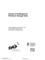
7.2.5 Two Vickers hardness traverses of the weld joint should be made on a weld sample in the minimum PWHT
condition. These hardness traverses should be performed within 1/16 in. (1.6 mm) from the internal and external
surfaces as shown in Figure 1. The HAZ readings should include locations as close as possible [approximately
0.008 in. (0.2 mm)] to the weld fusion line. Each traverse includes ten hardness readings for a total of 20 hardness
readings per weld sample. The hardness should not exceed 235 HV10 for conventional steels and 248 HV10 for
advanced steels.
7.2.6 A tensile test, transverse to the weld, should be performed on a weld joint of the heat treated test plate in the
PWHT condition required by Table 2, and should meet the ambient temperature properties specified for the base
metal in 5.5.2.
7.2.7 All WPSs/PQRs should be approved by the purchaser prior to fabrication.
MATERIALS AND FABRICATIONS OF 2 1/4CR-1MO, 2 1/4CR-1MO-1/4V, 3CR-1MO, AND 3CR-1MO-1/4V
STEEL HEAVY WALL PRESSURE VESSELS FOR HIGH-TEMPERATURE, HIGH-PRESSURE HYDROGEN SERVICE
B
A
G
WELD METAL
G
HA
Z
E (TYP)
1/16 in.
(1.5mm)
F
Z
HA
0.12D0.24 in.
(3-6mm)
C
0.04-0.12 in.
(1Ð3mm)
(TYP)
Approx
8 mil
(0.2mm)
11
BASE METAL
E
BASE METAL
F
WELD METAL
Key
A
B
C
D
Approx 8 mil (0.2 mm)
0.04 in. – 0.12 in. (1 mm – 3 mm) (TYP)
1/16 in. (1.5 mm)
0.12 in. – 0.24 in. (3 mm – 6 mm) (TYP)
E
F
G
Base Metal
Weld Metal
HAZ
Figure 1—Location of Vickers Hardness Indentations
7.3 Preheat and Heat Treatments During Base Metal Welding
7.3.1 Preheat
All base metal should be heated to a minimum of 300 °F (150 °C) for conventional steels and 350 °F (177 °C) for
advanced steels prior to and during all welding, rolling, thermal cutting and gouging operations (except during weld
overlay—see 7.5.4). During welding, the preheat temperature should be maintained until PWHT, ISR or DHT in
accordance with 7.3.2. The purpose is to drive out hydrogen to minimize the risk of hydrogen cracking, and to
minimize problems due to low as-welded toughness. For butt welding and attachment welding, this preheat
temperature should be maintained through the entire plate thickness for a distance of at least one plate thickness on
either side of the weld, but need not extend more than 4 in. (100 mm) in any direction from the edges to be welded.
7.3.2 Intermediate Stress Relief/Dehydrogenation Heat Treatment
7.3.2.1 General
Intermediate stress relief (ISR) is required before cooling below preheat temperature prior to PWHT, unless the
purchaser approves the use of dehydrogenation heat treatment (DHT). ISR should not be waived for restrained welds
such as all nozzle welds for advanced grades, and nozzle welds in conventional grades with shell or head
thicknesses 8 in. (200 mm) and greater.
Approval of DHT in lieu of ISR should be done only after careful consideration of the metallurgical factors and
possible risks. Higher concern levels with DHT are typically applied to advanced steels, as they can have low aswelded toughness. Although a DHT will remove hydrogen, it will not sufficiently restore toughness, especially for
advanced materials which remain very brittle during pre-PWHT handling. To approve the use of DHT, purchaser
requires test and/or experiential data. Typical information to be included in the manufacturer’s request should include
detailed information and data concerning hydrogen controls for procurement and handling of welding consumables,
12
API RECOMMENDED PRACTICE 934-A
hydrogen content of weld metals after the DHT, and nondestructive examination of weld joints. The purchaser may
require the manufacturer to demonstrate high sensitivity ultrasonic examination procedures to detect flaws at weld
joints after using a DHT.
Factors to be considered when reviewing possible use of DHT are the degree of weld restraint; weld joint thickness,
experience of the manufacturer, and type of steel. DHT is commonly allowed for conventional steels on nonrestrained welds such as shell welds and shell-to-head welds.
7.3.2.2 Intermediate Stress Relief (ISR)
An ISR soak in a furnace should be performed at the following metal temperatures:
— conventional steels, 1100 °F (593 °C) minimum for 2 hours minimum;
— advanced steels, 1200 °F (650 °C) minimum for 4 hours minimum, or 1250 °F (680 °C) minimum for 2 hours
minimum.
7.3.2.3 Dehydrogenation Heat Treatment (DHT)
The DHT should be performed at a minimum metal temperature of 570 °F (300 °C) for conventional steels, and
660 °F (350 °C) for advanced steels when approved by purchaser for duration to be agreed upon between the
manufacturer and the purchaser. In no case should the duration be less than one hour for conventional steels, and
four hours for advanced steels.
7.4 Production Testing of Base Metal Welds
7.4.1 Chemical Composition of Production Welds
7.4.1.1 The chemical composition of the weld deposit representing each different welding procedure should be
checked by either laboratory chemical analysis or by using a portable analyzer of equivalent accuracy and precision.
7.4.1.2 The chromium, molybdenum, vanadium, and columbium content (as applicable) of the weld deposits should
be within the ranges specified in ASME BPVC, Section II, Part C and ASME BPVC, Section VIII, Division 2, Table 3.2,
for the specified electrodes.
7.4.2 Hardness of Weld Deposit and Adjacent Base Metal
7.4.2.1 After final PWHT (see 7.6), hardness determinations should be made for each pressure-retaining weld using
a portable hardness tester.
7.4.2.2 Each hardness test result should be the average of three impressions at each test location. The test
locations should include weld metal and base metals adjacent to the fusion line on both sides. Hardness values of all
three locations should be reported.
7.4.2.3 Hardness values should not exceed:
— conventional steels, 225 HBW, or equivalent;
— advanced steels, 235 HBW, or equivalent.
7.4.2.4 Hardness tests should be performed on each 10 ft (3 m) length of weld, or fraction thereof. This testing
should be performed on the side exposed to the process environment when accessible.
MATERIALS AND FABRICATIONS OF 2 1/4CR-1MO, 2 1/4CR-1MO-1/4V, 3CR-1MO, AND 3CR-1MO-1/4V
STEEL HEAVY WALL PRESSURE VESSELS FOR HIGH-TEMPERATURE, HIGH-PRESSURE HYDROGEN SERVICE
13
7.4.3 Weld Impact Tests
7.4.3.1 Production test plates subjected to the minimum PWHT should meet ASME BPVC, Section VIII, Division 2,
Paragraph 3.11.8.4. Additional production test plate material, subjected to the maximum PWHT, should also be tested
and should meet the requirements of ASME BPVC, Section VIII, Division 2, Paragraph 3.11.8.4. The impact test
temperature and acceptance criteria should be in accordance with 5.5.3.1.
7.4.3.2 Production test plates subjected to the minimum PWHT should be impact tested before and after step
cooling in accordance with the requirements of 6.2.3 unless waived by the purchaser.
7.5 Weld Overlay
7.5.1 Material Requirements
The ferrite content of austenitic stainless steel weld overlay should be between 3 FN and 10 FN, as determined in
accordance with WRC Bulletin 342, prior to any PWHT except that the minimum ferrite content for Type 347 should
be 5 FN (in accordance with API 582).
7.5.2 Disbonding Tests
7.5.2.1 When required by the purchaser, a method to evaluate the weld overlay for susceptibility to hydrogen
disbonding should be agreed to between the manufacturer and purchaser. The purchaser should define testing
requirements and acceptance criteria. The test parameters should represent or exceed the equivalent of actual
maximum operating conditions (hydrogen partial pressure, temperature, and cooling rates). The test conditions are
modified to be “equivalent” based on the test specimen size, geometry, and hydrogen charging as shown by the test
domains in 7.5.2.3.
7.5.2.2 Results of disbonding tests should be available, prior to fabrication, for each welding procedure to be used
on the vessel shell rings and heads. Previously qualified disbonding test results can be submitted for review by the
purchaser if representative of the proposed WPS and operating conditions.
7.5.2.3 Proposed testing conditions representing or exceeding the equivalent of actual maximum operating service
are indicated in Table 3. Six domains of test conditions, depending on reactor wall thickness, pressure, and
temperature, are defined in Table 4.
14
API RECOMMENDED PRACTICE 934-A
Table 3—Maximum Operation Conditions Correlated to Testing Conditions at 450 °C (842 °F)
Reactor Service Conditions
Thickness
mm (in.)
≥ 250 (9.84)
≥ 180 < 250
(≥ 7.09 < 9.84)
≥ 130 < 180
(≥ 5.12 < 7.09)
Max. Operating Pressure
bar (psi)
Max. Operating Temperature
≥ 450 °C (842 °F)
425 °C – 449 °C
(797 °F – 840 °F)
< 425 °C
(797 °F)
≥ 170 (2465)
A
B
C
≥ 140 < 170 (≥ 2030 < 2465)
B
C
D
≥ 140 (2030)
B
C
D
≥ 110 < 140 (≥ 1595 < 2030)
C
D
E
≥ 80 < 110 (≥ 1160 < 1595)
D
E
F
≥ 110 (1595)
C
D
E
≥ 80 < 110 (≥ 1160 < 1595)
D
E
F
≥ 60 < 80 (≥ 870 < 1160)
E
F
F
< 60 (870)
F
F
F
≥ 80 (1160)
D
E
F
≥ 60 < 80 (≥ 870 < 1160)
E
F
F
< 60 (870)
F
F
F
≥ 80 < 100
(≥ 3.15 < 3.94)
≥ 60 (870)
E
F
F
< 60 (870)
F
F
F
< 80 (3.15)
< 60 (870)
F
F
F
≥ 100 < 130
(≥ 3.94 < 5.12)
Table 4—Test Conditions Domains
Testing Conditions
Domain
Temperature
°C (°F)
Pressure
bar (psi)
Cooling Rate
(°C/h) (°F/h)
Aa
450 (842)
150 (2175)
675 (1247)
B
450 (842)
150 (2175)
150 (302)
C
450 (842)
120 (1740)
150 (302)
D
450 (842)
90 (1305)
150 (302)
E
450 (842)
70 (1015)
150 (302)
F
450 (842)
50 (725)
150 (302)
a
For Domain A, the following equivalent testing conditions may be used as an alternate:
— temperature, 842 °F (450 °C);
— pressure, 175 bar (2538 psi);
— cooling rate, 302 °F/h (150 °C/h).
7.5.2.4 For 2 1/4Cr-1Mo reactors where the operating conditions fall into the D, E, and F domains, the risk of
disbonding is very low and the purchaser can determine if testing is necessary. Vanadium-modified grades are
significantly less susceptible to disbonding in any domain [1, 2]. The purchaser may consider and evaluate
manufacturer’s existing disbonding test results, under similar conditions, for acceptability.
7.5.2.5 Test specimen should meet ASTM G146 standards and acceptable test results for such testing conditions
should be Area Ranking A of same.
7.5.3 Weld Overlay Procedure Qualification
7.5.3.1 The selected weld overlay process and the number of layers should be qualified in accordance with ASME
BPVC, Section IX.
MATERIALS AND FABRICATIONS OF 2 1/4CR-1MO, 2 1/4CR-1MO-1/4V, 3CR-1MO, AND 3CR-1MO-1/4V
STEEL HEAVY WALL PRESSURE VESSELS FOR HIGH-TEMPERATURE, HIGH-PRESSURE HYDROGEN SERVICE
15
7.5.3.2 Procedure qualification tests should be made on base metal of the same ASME specification (same Pnumber and Group number) and similar chemistry as specified for the vessel, but either plate or forging may be used.
Thickness of the test specimen should not be less than one-half the thicknesses of the vessel base metal or 2 in.
(50 mm.), whichever is less. The welding electrode, wire, and flux used for the weld overlay procedure qualification
should be the same type and brand to be used in production.
7.5.3.3 The qualification test plates should be subjected to the maximum PWHT condition.
7.5.3.4 The chemical composition of the weld overlay should be checked by chemical analysis of samples taken at
minimum specified thickness from the process side. It should meet the specified composition of the weld overlay (final
layer if multiple layers). The chemical composition, determined by these samples, should be used to calculate the
ferrite content in accordance with 7.5.1.
7.5.4 Preheat and Heat Treatments During Weld Overlay
Base metal should be preheated to 200 °F (94 °C) for the first layer of weld overlay. The maximum interpass
temperature should be 350 °F (175 °C). Provided that subsequent still-air cooling is applied, intermediate stress relief
(ISR) may be omitted after overlay welding. No preheating is required for the second and any subsequent layers of
weld overlay.
7.5.5 Production Testing of Weld Overlay
7.5.5.1 Chemical Composition of Weld Overlay
The chemical composition of the weld overlay should be checked by laboratory chemical analysis of a sample taken
at minimum specified thickness. This composition should meet the required chemistry of the specified overlay
material (C, Cr, Ni, Nb, Mo, and V, as applicable). At least one analysis for each shell ring and head, and one for each
manual welding process for nozzles, should be required.
7.5.5.2 Ferrite Content of Weld Overlay
7.5.5.2.1 A magnetic instrument calibrated to AWS A4.2 should be used to check the ferrite content of the
production weld overlay prior to any PWHT.
7.5.5.2.2 Calibration for the steel backing material in accordance with AWS A4.2, Appendix A7, Paragraph A7.1
may be used.
7.5.5.2.3 A minimum of six ferrite readings should be taken on the surface at each of the following locations:
a) at least ten locations, selected at random, should be checked for each shell ring and head;
b) two locations for each nozzle overlay (one at each end);
c) one location on cladding or overlay restoration of each Category A, B, and D welds, if applicable.
7.5.5.2.4 The value of all ferrite readings at each location should meet the requirements in 7.5.1.
7.6 Final Postweld Heat Treatment (PWHT)
7.6.1 The fabricated vessel should be postweld heat treated as a whole in an enclosed furnace whenever possible.
When vessel size does not allow PWHT as a whole in a furnace, PWHT may be performed sectionally according to
ASME BPVC, Section VIII, Division 2, Paragraph 6.4.3.3.
Final PWHT temperature and holding time should be as shown in Table 5.
16
API RECOMMENDED PRACTICE 934-A
Table 5—PWHT Holding Temperature and Time
Material
PWHT Temperature
Holding Time
Conventional Steels
1275 °F ± 25 °F (690 °C ± 14 °C)
See footnote a.
Advanced Steels
1300 °F ± 25 °F (705 °C ± 14 °C)
8 hours, minimumb
a
In accordance with ASME BPVC, Table 6.11.
The electrode manufacturers have developed their materials for thicker welds, and even with thinner welds, this longer heat
treatment is needed to meet toughness and tensile properties. ASME BPVC, Section VIII, Division 2 requirements (see Table
6.11) must also be met if stricter.
b
7.6.2 The PWHT temperature should be strictly controlled, measuring both the vessel skin and furnace
temperatures using thermocouples, including any portion of the vessel outside of the furnace. Any section of the
vessel outside the furnace should be insulated such that the temperature gradient is not harmful. Thermocouple
arrangements should be established for each heat treatment. The skin temperature should be measured and
controlled on the inside and outside of the vessel.
7.6.3 Continuous time-temperature records of all PWHT operations should be documented to meet ASME BPVC,
Section VIII, Division 2, Paragraph 6.4.4.
8 Nondestructive Examinations (NDE)
8.1 General
All NDE personnel should be qualified in accordance with ASNT SNT-TC-1A. Personnel interpreting and reporting
results should also be qualified to the same practice.
8.2 NDE Prior to Fabrication
8.2.1 Ultrasonic Testing (UT)
8.2.1.1 As required by ASME BPVC, Section VIII, Division 2, Paragraph 3.3.3, all base metal plates should be
ultrasonically examined with 100 % scanning in accordance with ASME SA-435 and ASME SA-578, Level C,
Supplementary Requirement S1, before forming.
8.2.1.2 All forgings for shell rings, nozzles, and manways should be ultrasonically examined with 100 % scanning in
accordance with ASME BPVC, Section VIII, Division 2, Paragraph 3.3.4.
8.2.2 Magnetic Particle Testing (MT) or Dye Penetrant Testing (PT)
8.2.2.1 Entire surfaces of all forgings, including welding edges, should be examined by MT in accordance with
ASME BPVC, Section VIII, Division 2, Paragraph 7.5.6, or by PT in accordance with ASME BPVC, Section VIII,
Division 2, Paragraph 7.5.7. Examination should be after finish machining but before welding.
8.2.2.2 Entire surfaces of all formed plates to be welded for shell rings and heads, including those for weld overlay,
should be examined by either MT or PT, as noted in 8.2.2.1. For formed plates to be welded for shell rings and heads,
welding edges should be examined by MT or PT after forming.
8.3 NDE During Fabrication
8.3.1 MT should be performed after completion of all welds excluding stainless weld overlay. This includes pressure
retaining base metal welds, weld build-up deposits, root passes and attachment welds. MT should also be performed
after any gouging or grinding operation including back gouging of root passes. MT should be in accordance with
ASME BPVC, Section VIII, Division 2, Paragraph 7.5.6.