Bsi bs au 007a 1983 (2000)
Bạn đang xem bản rút gọn của tài liệu. Xem và tải ngay bản đầy đủ của tài liệu tại đây (415.17 KB, 14 trang )
BRITISH STANDARD AUTOMOBILE SERIES
Specification for
Colour code for road
vehicle electrical cables
UD C 62 9. 1 1 3. 066: 621 . 31 5. 2 - 777. 6
BS AU 7a:1983
BS AU 7a:1983
Committees responsible for this
British Standard
The preparation of this British Standard was entrusted by the Automobile
Standards Committee (AUE- ) to Technical Committee AUE/1 6 upon which the
following bodies were represented:
Association of Trailer Manufacturers
Department of Transport
Electric Cable Makers’ Confederation
National Caravan Council Limited
Society of Motor Manufacturers and Traders Limited
This British Standard, having
been prepared under the
direction of the Automobile
Standards Committee, was
published under the authority
of the Board of BSI and comes
into effect on
30 December 1 983
First published February 1 963
First revision June 1 968
Second revision December 1 983
© BSI 02- 2000
The following BSI references
relate to the work on this
standard:
Committee reference AUE/1 6
Draft for comment 81 /71 785 DC
ISBN 0 580 13554 3
Amendments issued since publication
Amd. No.
Date of issue
Comments
BS AU 7a:1983
Contents
Page
Committees responsib le
© BSI 02 - 2 000
Inside front cover
Foreword
ii
1
Scope
1
2
C ab le colours
1
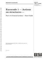
Figure 1 — Basic circuits
8
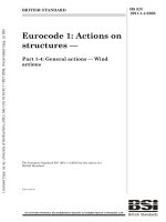
Figure 2 — Supplementary circuits
9
Tab le 1 — Cable colour code
1
i
BS AU 7 a: 1 983
Fore word
This British Standard has been prepared under the direction of the Automobile
Standards Committee. It supersedes BS AU 7: 1 968 which is withdrawn. This
revision brings the standard up to date with subsequent developments in vehicle
electrical equipment.
For the information of the user the destinations of the cables in the previous 1 968
edition of this standard have been included. New cables, reference numbers 1 21
to 1 33, have been added to this standard.
A British Standard does not purport to include all the necessary provisions of a
contract. Users of British Standards are responsible for their correct application.
C omp liance with a British S tand ard d oe s no t of itse lf confe r immunity
from le gal ob ligatio ns.
S ummary of p age s
This document comprises a front cover, an inside front cover, pages i and ii,
pages 1 to 9 and a back cover.
This standard has been updated (see copyright date) and may have had
amendments incorporated. This will be indicated in the amendment table on the
inside front cover.
ii
© BSI 02- 2000
BS AU 7a:1 983
1 Scope
2 Cable colours
This British Standard specifies requirements for a
Cable colours for related cable functions shall be as
colour code for electrical cables used in road vehicles
specified in Table 1 and in Figure 1 , for basic
that identifies each circuit by the colour of the cables
circuits; and Table 1 and Figure 2, for
used.
supplementary circuits.
NOTE
Due to the variation in design of some components, such
as windscreen wiper motors, it is not possible to include all
switches and internal wiring arrangements. The component
manufacturers should be consulted for further details.
Where two colours are specified, the first colour
shall be the primary colour and the second colour
shall be the tracer.
Table 1 — Cable colour code
Cable
Cable colour
Cable destination
Cable destination in 1 968 version of
ref. no.
BS AU 7 (for information)
1
Brown
Main battery feed
2
Brown with blue
Control box (compensated voltage
Control box (compensated voltage
control only) to ignition and
control only) to ignition and
lighting switch (feed)
lighting switch (feed)
3
Brown with red
Main battery feed
Compression ignition starting aid
Compression ignition starting aid
to switch. Main battery feed to
to switch. Main battery feed to
double pole ignition switch
double pole ignition switch (a. c. alt,
system)
4
Brown with purple
Alternator regulator feed
Alternator regulator feed
5
Brown with green
Dynamo “F” to control box “F”.
Dynamo “F” to control box “F”.
6
Brown with light
Alternator field “F” to control box
Alternator field “F” to control box
“F”
“F”
Spare
Screenwiper motor to switch (now
green
transferred to cable ref.
nos. 1 22, 1 23 and 1 24)
7
8
Brown with white
Brown with yellow
Ammeter to control box. Ammeter
Ammeter to control box
to main alternator terminal
Ammeter to main alternator
Alternator to “no change” warning
Dynamo “D” to control box “D” and
light
ignition warning light. Alternator
neutral point
9
Brown with black
Alternator battery sensing lead
Alternator warning light, negative
side
10
Brown with pink
Spare
Spare
11
Brown with slate
Starter relay contact to starter
Spare
solenoid
12
Brown with orange
Fuel shut- off (diesel stop)
Spare
13
Blue
Lighting switch (head) to dipper
Lighting switch (head) to dipper
switch
switch
14
Blue with brown
Headlamp relay to headlamp fuse
Spare
15
Blue with red
Dipper switch to headlamp dip
Dipper switch to headlamp dip
beam fuse. Fuse to right- hand dip
beam. Headlamp dip beam fuse to
headlamp
right- hand headlamp
(when independently fused)
16
Blue with purple
Spare
Spare
17
Blue with green
Spare
Spare
18
Blue with light
Headlamp wiper motor to
Screenwiper motor to switch
green
headlamp wash pump motor
© BSI 02- 2000
1
BS AU 7a:1 983
Table 1 — Cable colour code
Cable
Cable colour
Cable destination
Cable destination in 1 968 version of
ref. no.
19
BS AU 7 (for information)
Blue with white
a) Dipper switch to headlamp main
Dipper switch to headlamp main
beam fuse
beam (subsidiary circuit: headlamp
b) Headlamp flasher to main beam
flasher relay to headlamp).
fuse
Headlamp main beam fuse to
c) Dipper switch main beam
right- hand headlamp
warning light
(when independently fused).
d) Dipper switch to long- range
Headlamp main beam fuse to
driving light switch
outboard headlamps (when
outboard headlamps independently
fused). Dipper switch to main beam
warning light.
20
Blue with yellow
Long- range driving light switch to
Long- range driving switch to lamp
lamp
21
Blue with black
Fuse to right- hand main headlamp
Spare
22
Blue with pink
Fuse to left- hand dip headlamp
Headlamp dip beam fuse to
left- hand headlamp when
independently fused
23
Blue with slate
Headlamp main beam fuse to
Headlamp main beam fuse to
left- hand headlamp or inboard
left- hand headlamp or inboard
headlamps when independently
headlamps when independently
fused
fused
24
Blue with orange
Fuse to right- hand dip headlamp
Spare
25
Red
Main feed to all circuits mastered
Side and tail lamp feed
by sidelamp switch
26
Red with brown
Rear fog guard switch to lamps
Variable intensity panel lights
(when used in addition to normal
panel lights)
27
Red with blue
Front fog lamp fuse to fog lamp
Spare
switch
28
Red with purple
Switches to map light, under
Map light switch to map light
bonnet light, glove box light and
boot lamp when side lamp circuit
fed
29
30
Red with green
Red with light
Bulb failure unit to right- hand side
Lighting switch to side and tail
and rear lamps
lamp fuse (when fused)
Spare
Screenwiper motor to switch
a) Sidelamp fuse to right- hand side
Panel light switch to panel lights
green
31
Red with white
and rear lamps
b) Sidelamp fuse to panel light
rheostat, panel light or map light
c) Fuse to panel light switch or
rheostat
d) Fuse to fibre optic source
32
Red with yellow
Fog lamp switch to fog lamp or
Fog lamp switch to fog lamp
front fog fuse to fog lamps
33
Red with black
Side lamp fuse to side and tail
Parking light switch to left- hand
lamps, left- hand and number plate
sidelamp
illumination
2
© BSI 02- 2000
BS AU 7a:1 983
Table 1 — Cable colour code
Cable
Cable colour
Cable destination
Cable destination in 1 968 version of
ref. no.
BS AU 7 (for information)
34
Red with pink
Sidelamp fuse to lighting relay
Spare
35
Red with slate
Lamp failure unit to left- hand side
Spare
and tail lamps
36
Red with orange
Fusebox to rear fog guard switch
Parking light switch to right- hand
sidelamp
37
38
39
Purple
Purple with brown
Purple with blue
Accessories fed direct from battery
Accessories fused direct from
via fuse
battery
Horn fuse to horn relay when horn
Horn fuse to horn relay (when horn
is fused separately
is fused separately)
Fuse to heated rear window relay
Spare
or switch and warning light
40
Purple with red
Switches to map light, under
Boot light switch to boot light
bonnet light, glove box light and
boot lamp when fed direct from
battery fuse
41
42
Purple with green
Fuse to hazard flasher
Spare
Purple with light
Fuse to relay for screen demist
Spare
green
43
Purple with white
Interior lights to switch (subsidiary
Interior light to switch (subsidiary
circuit: door safety lights to switch)
circuit: door safety lights to switch)
44
Purple with yellow
Horn to horn relay
Horn to horn relay
45
Purple with black
Horn to horn relay to horn push
Horn to horn relay to horn push
46
Purple with pink
Rear heated window to switch or
Spare
relay
47
Purple with slate
Aerial lift motor to switch up
Aerial lift motor to switch up
48
Purple with orange
Aerial lift motor to switch down
Aerial lift motor to switch down
49
Green
Accessories fused via ignition
Accessories fused via ignition
switch
switch (subsidiary circuit fuse A4
to hazard switch terminal 6)
50
Green with brown
Switch to reverse lamp
Reverse lamp to switch
51
Green with blue
Water temperature gauge to
Water temperature gauge to
temperature unit
temperature unit
Direction indicator switch to
Left- hand flasher lamps
52
Green with red
left- hand flasher lamps
53
Green with purple
Stop lamp switch to stop lamps;
Stop lamps to stop lamp switch
or
stop lamp switch to lamp failure
unit
54
Green with light
Hazard flasher unit to hazard pilot
Hazard flasher unit to hazard pilot
green
lamp;
lamp
or
lamp failure unit to stop lamp bulbs
55
Green with white
Direction indicator switch to
Right- hand flasher lamps
right- hand flasher lamps
56
Green with yellow
© BSI 02- 2000
Heater motor to switch single
Heater motor to switch, single
speed (or to “slow” on two or
speed (or to “slow” on two- speed
three- speed motor)
motor)
3
BS AU 7a:1 983
Table 1 — Cable colour code
Cable
Cable colour
Cable destination
Cable destination in 1 968 version of
ref. no.
57
BS AU 7 (for information)
Green with black
Fuel gauge to fuel tank unit or
Fuel gauge to fuel tank unit or
changeover switch or voltage
changeover switch
stabilizer to tank units
58
Green with pink
Fuse to flasher unit
Choke solenoid to choke switch
(when fused)
59
Green with slate
a) Heater motor to switch (“fast” on
Heater motor to switch (fast on
two or three- speed motor)
two- speed motor)
b) Coolant level unit to warning
light
60
Green with orange
Low fuel level switch to warning
Low fuel level warning light
light
61
62
Light green
Light green with
Instrument voltage stabilizer to
Instrument voltage stabilizer to
instruments
instruments
Flasher switch to flasher unit
Flasher switch to flasher unit
brown
63
Light green with
a) Flasher switch to left- hand
Flasher switch to left- hand flasher
blue
flasher warning light
warning light
b) Coolant level sensor to control
unit
c) Test switch to coolant level
control unit
64
Light green with
Fuel tank changeover switch to
Fuel tank changeover switch to
red
right- hand tank unit;
right- hand tank unit
or
entry and exit door closed switch to
door actuator
65
66
Light green with
Flasher unit to flasher warning
Flasher unit to flasher warning
purple
light
light
Light green with
Start inhibitor relay to change
Spare
green
speed switch;
or
switch to heater blower motor
second speed on three- speed unit
67
68
Light green with
Low air pressure switch to buzzer
white
and warning light
Spare
Light green with
Flasher switch to right- hand
Flasher switch to right- hand
yellow
warning light;
flasher warning light
or
differential lock switch, to
differential lock warning light
69
70
71
Light green with
Front screen j et switch to screen j et
Screen j et switch to screen j et
black
motor
motor
Light green with
Hazard flasher unit to hazard
Flasher unit to emergency switch
pink
switch
(simultaneous flashing)
Light green with
Fuel tank changeover switch to
Fuel tank changeover switch to
slate
left- hand tank unit;
left- hand tank unit
or
entry and exit door open switch to
door actuator
4
© BSI 02- 2000
BS AU 7a:1 983
Table 1 — Cable colour code
Cable
Cable colour
Cable destination
Cable destination in 1 968 version of
ref. no.
72
BS AU 7 (for information)
Light green with
Rear window wash switch to wash
orange
pump;
Spare
or
cab lock- down switch to warning
light
73
74
White
White with brown
Ignition switch or starter solenoid
Ignition controlled circuit (unfused)
to ballast resistor
(ignition switch to ballast resistor)
Oil pressure switch to warning
Oil pressure switch to warning
light or gauge;
light or gauge
or
starter relay to oil pressure switch
75
White with blue
Choke switch to choke solenoid
Choke switch to choke solenoid
(unfused) and/or choke to switch to
(unfused). Rear heater fuse unit to
warning light; or electronic ignition
switch. Electronic ignition
distributor to drive resistor
transistor assisted contact ignition
unit to resistance
76
White with red
Starter switch to starter solenoid or
Solenoid starter switch to starter
inhibitor switch or starter relay;
push or inhibitor switch
or
ignition (start position) to bulb
failure unit
77
78
79
White with purple
White with green
Fuel pump no. 1 or right- hand to
Fuel pump no. 1 or right- hand to
changeover switch
changeover switch
Fuel pump no. 2 or left- hand to
Fuel pump no. 2 or left- hand to
changeover switch
changeover switch
White with light
Start switch to starter interlock;
Screenwiper motor to switch
green
or
oil pressure switch to fuel pump;
or
start inhibitor switch to starter
relay or solenoid
80
White with yellow
Ballast resistor to coil; or starter
Starter push inhibitor switch to
solenoid to coil
starter push. Ballast resistor to coil
Starter solenoid to coil
81
White with black
Ignition coil contact breaker to
Ignition coil contact breaker to
distributor contact breaker;
distributor contact breaker. Rear
or
heated window to switch or fuse
distributor side of coil to voltage
transistor assisted contact ignition
impulse tachometer
82
White with pink
Ignition switch to radio fuse
Radio from ignition switch
83
White with slate
Current tachometer to ignition coil
Tachometer to ignition coil
84
White with orange
Hazard warning feed to switch
Hazard warning feed (to switch)
85
Yellow
a) Overdrive
Overdrive
b) Petrol inj ection no. 1
c) Door locks
d) Gear selector switch to start
86
Yellow with brown
a) Petrol inj ection no. 2
Overdrive
b) Door locks
© BSI 02- 2000
5
BS AU 7a:1 983
Table 1 — Cable colour code
Cable
Cable colour
Cable destination
Cable destination in 1 968 version of
ref. no.
87
BS AU 7 (for information)
Yellow with blue
a) Overdrive
Overdrive
b) Petrol inj ection no. 3
c) Door locks
88
Yellow with red
a) Petrol inj ection no. 4
Overdrive
b) Door locks
89
Yellow with purple
a) Overdrive
Overdrive
b) Petrol inj ection no. 5
c) Door locks
90
Yellow with green
a) Overdrive
Overdrive
b) Petrol inj ection no. 6
c) Door locks
91
92
Yellow with light
a) Petrol inj ection no. 7
green
b) Door locks
Yellow with white
a) Petrol inj ection no. 8
Screenwiper motor to switch
Spare
b) Door locks
93
Yellow with black
Door locks
Spare
94
Yellow with pink
Door locks
Spare
95
Yellow with slate
Door locks
Spare
96
Yellow with orange
Door locks
Spare
97
Black
All earth connections
All earth connections
98
Black with brown
99
1 00
Black with blue
Black with red
Tachometer generator to
Tachometer generator to
tachometer
tachometer
Tachometer generator to
Tachometer generator to
tachometer
tachometer
Electric or electronic speedometer
Electric speedometer
to sensor
1 01
Black with purple
Temperature switch to warning
Spare
light
1 02
Black with green
Relay to radiator fan motor
Screenwiper switch to screenwiper
(single speed). Relay to radiator fan
motor
1 03
Black with light
Vacuum brake switch or brake
Vacuum brake switch to warning
green
differential pressure valve to
light and/or buzzer
warning light and/or buzzer
1 04
Black with white
Brake fluid level warning light to
Brake fluid level warning light to
switch and handbrake switch;
switch and handbrake switch
or
radio to speakers
1 05
Black with yellow
Electric speedometer
Electric speedometer
1 06
Black with pink
Spare
Spare
1 07
Black with slate
Spare
Spare
1 08
Black with orange
Radiator fan motor to thermal
Radiator fan motor to thermal
switch
switch
1 09
Slate
Window lift main feed
Window lift
110
Slate with brown
Window lift main feed
Window lift
6
© BSI 02- 2000
BS AU 7a:1 983
Table 1 — Cable colour code
Cable
Cable colour
Cable destination
Cable destination in 1 968 version of
ref. no.
BS AU 7 (for information)
111
Slate with blue
Window lift main feed
Window lift
112
Slate with red
Window lift main feed
Window lift
113
Slate with purple
Window lift main feed
Window lift
114
Slate with green
Window lift main feed
Window lift
Slate with light
Window lift main feed
Window lift
115
green
116
Slate with white
Window lift main feed
Window lift
117
Slate with yellow
Window lift main feed
Window lift
118
Slate with black
Window lift main feed
Window lift
119
Slate with pink
Window lift main feed
Window lift
1 20
Slate with orange
Window lift main feed
Window lift
1 21
Orange
Wiper circuits fused via ignition
—
switch
1 22
Orange with blue
Switch to front screen wiper motor
—
first speed, timer or intermittent
unit
1 23
Orange with green
Switch to front screen wiper motor
—
second speed
1 24
Orange with black
Switch to front screen wiper motor
—
parking circuit, timer or
intermittent unit
1 25
Orange with purple Timer or intermittent unit to motor
—
first speed
1 26
Orange with white
Timer or intermittent unit to motor
—
parking circuit
1 27
Orange with yellow Switch to headlamp or rear window
—
wiper motor feed, timer or relay
coil
1 28
Orange with light
Switch to headlamp or rear window
green
wiper motor parking circuit timer
—
or relay coil
1 29
Orange with pink
Timer or relay to headlamp or rear
—
window wiper motor feed
1 30
Orange with slate
Timer or relay to headlamp or rear
—
window wiper motor parking
circuit
1 31
Orange with brown
Spare
—
1 32
Orange with red
Spare
—
1 33
Pink with white
Ballast resistor to distributor
—
(optionally marked “RESISTIVE”)
NOTE
Cables ref. numbers 1 21 to 1 33 are new cables added to the standard in this 1 983 issue.
© BSI 02- 2000
7
Figure 1 — Basic circuits
BS AU 7a:1983
8
© BSI 02 - 2 000
Figure 2 — Supplementary circuits
BS AU 7a:1983
© BSI 02 - 2 000
9
BS AU 7a:1983
BSI — British Standards Institution
BS I is the indep endent national b ody res p ons ib le for p rep aring
Britis h S tandards . It p res ents the UK view on s tandards in E urop e and at the
international level. It is incorp orated b y Royal C harter.
Revisions
Britis h S tandards are up dated b y amendment or revis ion. Us ers of
Britis h S tandards should make s ure that they p oss es s the latest amendments or
editions .
It is the constant aim of BS I to imp rove the quality of our p roducts and services .
We would b e grateful if anyone finding an inaccuracy or amb iguity while us ing
this Britis h S tandard would inform the S ecretary of the technical committee
res p ons ib le, the identity of which can b e found on the inside front cover.
Tel: 02 0 89 96 90 00. Fax: 02 0 89 96 7 40 0 .
BS I offers memb ers an individual up dating s ervice called PLUS which ens ures
that s ub s crib ers automatically receive the lates t editions of s tandards .
Buying standards
O rders for all BS I, international and foreign s tandards p ub lications s hould b e
addres s ed to C us tomer S ervices. Tel: 0 2 0 899 6 9 00 1 . Fax: 0 2 0 899 6 7001 .
In res p ons e to orders for international standards , it is BS I p olicy to sup p ly the
BS I imp lementation of thos e that have b een p ub lis hed as Britis h S tandards,
unless otherwis e requested.
Information on standards
BS I p rovides a wide range of information on national, E urop ean and
international standards through its Lib rary and its Technical H elp to E xp orters
S ervice. Various BS I electronic information s ervices are also availab le which give
details on all its p roducts and s ervices . C ontact the Information C entre.
Tel: 02 0 89 96 71 1 1 . Fax: 02 0 89 96 7 048.
S ub s crib ing memb ers of BS I are kep t up to date with s tandards develop ments
and receive sub s tantial discounts on the p urchase p rice of s tandards. For details
of thes e and other b enefits contact Memb ership Adminis tration.
Tel: 02 0 89 96 70 02 . Fax: 02 0 89 96 7 00 1 .
Copyright
C op yright s ub s is ts in all BS I p ub lications . BS I als o holds the cop yright, in the
UK, of the p ub lications of the international s tandardization b odies . E xcep t as
p ermitted under the C op yright, D es igns and Patents Act 1 988 no extract may b e
rep roduced, s tored in a retrieval s ystem or transmitted in any form or b y any
means – electronic, p hotocop ying, recording or otherwis e – without p rior written
p ermis s ion from BS I.
This does not p reclude the free us e, in the cours e of imp lementing the standard,
of necess ary details such as s ymb ols, and size, typ e or grade designations. If thes e
details are to b e used for any other p urp os e than imp lementation then the p rior
written p ermiss ion of BS I must b e ob tained.
If p ermis sion is granted, the terms may include royalty p ayments or a licensing
agreement. D etails and advice can b e ob tained from the C op yright Manager.
BS I
3 89 C his wick H igh Road
London
W4 4AL
Tel: 02 0 89 96 70 7 0.