Bsi bs au 050 1 1 3 1993 (1999) iso 8767 1992
Bạn đang xem bản rút gọn của tài liệu. Xem và tải ngay bản đầy đủ của tài liệu tại đây (467.19 KB, 15 trang )
BRITISH STANDARD AUTOMOBILE SERIES
BS AU
50-1 .3:1 993
ISO 8767:1 992
Tyres and wheels —
Part 1 : Tyres —
Section 1 : Car tyres —
Subsection 1 .3 Method of measuring
rolling resistance
Reprodu ced by I H S u n d er l i cen se wi th BSI - U n con trol l ed Copy
BS AU 5 0-1 .3:1 993
Committees responsible for this
British Standard
The preparation of this British Standard was entrusted by the Automobile
Standards Policy Committee (AUE/- ) to Technical Committee AUE/4, upon
which the following bodies were represented:
Agricultural Engineers’ Association
Automobile Association
British Industrial Truck Association
British Pressure Gauge Manufacturers’ Association
British Rubber Manufacturers’ Association
Bus and Coach Council
Department of Transport
Freight Transport Association
Institute of Road Transport Engineers (Inc)
Motor Cycle Industry’s Association of Great Britain Ltd.
Motor Industry Research Association
National Tyre Distributors’ Association
Retread Manufacturers’ Association
Road Haulage Association Ltd.
Society of Motor Manufacturers and Traders Ltd.
This British Standard, having
been prepared under the
direction of the Automobile
Standards Policy Committee,
was published under the
authority of the Standards Board
and comes into effect on
Amendments issued since publication
1 5 January 1 993
Amd. No.
© BSI 1 2- 1 999
The following BSI references
relate to the work on this
standard:
Committee reference AUE/4
Draft for comment 89/73799 DC
ISBN 0 5 80 21 5 22 9
Reprodu ced by I H S u n d er l i cen se wi th BSI - U n con trol l ed Copy
Date
Comments
BS AU 5 0-1 .3:1 993
Contents
Page
Committees responsible
National foreword
Inside front cover
ii
1
Scope
1
2
Definitions
1
3
Test methods
1
4
Test equipment
1
5
Test conditions
2
6
Test procedure
2
7
Data interpretation
3
8
Data analysis
4
Annex A (normative) Test equipment tolerances
5
Annex B (informative) Optional test conditions
6
Annex C (informative) Measurement methods of
moment of inertia for drum and tyre assembly —
Deceleration method
6
Figure 1 — Free- body diagram of tyre/drum system,
© BSI 1 2- 1 999
Reprodu ced by I H S u n d er l i cen se wi th BSI - U n con trol l ed Copy
assuming no bearing and windage losses
3
Figure C. 1 — Arrangement
6
Figure C. 2 — Spring method
7
Figure C. 3 — Bifilar pendulum (rope) method
7
Table B. 1
6
i
BS AU 5 0-1 .3:1 993
National foreword
This Subsection of this Part of BS AU 50 has been prepared under the direction
of the Automobile Standards Policy Committee and is identical with
ISO 8767: 1 992
Pas senger car tyres — Methods of m easuring rolling resistance,
published by the International Organization for Standardization (ISO). Other
Parts of this standard are as follows:
—
Part 2: Wheels and rim s;
—
Part 3: Valv es;
—
Part 4: Rim p rofiles and dim ensions.
A British Standard does not purport to include all the necessary provisions of a
contract. Users of British Standards are responsible for their correct application.
Compliance with a British Standard does not of itself confer immunity
from legal obligations.
Summary of pages
This document comprises a front cover, an inside front cover, pages i and ii,
pages 1 to 8 and a back cover.
This standard has been updated (see copyright date) and may have had
amendments incorporated. This will be indicated in the amendment table on the
inside front cover.
ii
Reprodu ced by I H S u n d er l i cen se wi th BSI - U n con trol l ed Copy
© BSI 1 2- 1 999
BS AU 5 0-1 .3:1 993
2.5
1 Scope
This International Standard specifies methods for
parasitic loss
measuring rolling resistance, under controlled
loss of energy (or energy consumed) per unit
laboratory conditions, for new pneumatic tyres
distance excluding tyre losses, and attributable to
designed primarily for use on passenger cars. The
aerodynamic loss, bearing friction and other sources
relationship between values obtained and the fuel
of systematic loss which may be inherent in the
economy of the vehicle is undetermined, and such
measurement
values are not intended to be used to indicate levels
2.6
of performance or quality.
skim reading
This International Standard applies to all
type of parasitic loss measurement, in which the
passenger car tyres.
tyre is kept rolling, without slip page, while
It enables comparisons to be made between the
reducing the tyre load to a level at which energy loss
rolling resistance of new tyres when they are
within the tyre itself is virtually zero
free- rolling straight ahead, in a position
perpendicular to the drum outer surface, and in
steady- state conditions.
In measuring tyre rolling resistance, it is necessary
to measure small forces in the presence of much
larger forces. It is, therefore, essential that
2.7
machine reading
type of parasitic loss measurement, involving losses
of the test machine, exclusive of losses in the
rotating spindle which carries the tyre and rim
equipment and instrumentation of appropriate
2.8
accuracy be used.
moment of inertia
(see Annex C)
2 Definitions
For the purposes of this International Standard, the
following definitions apply.
2.1
rolling resistance:
The following alternative measurement methods
are given in this International Standard. The choice
F
of an individual method is left to the tester. For each
r
loss of energy (or energy consumed) per unit of
distance
NOTE 1
3 Test methods
method, the test measurements shall be converted
to a rolling resistance force acting at the tyre/drum
interface.
The SI unit conventionally used for the rolling
resistance is the newton metre per metre (N·m/m) .
This is equivalent to the drag force in newtons (N) .
2.2
rolling resistance coefficient:
C
r
a) Force method: the reaction force at the tyre
spindle.
b) Torque method: the torque input to the test
drum.
ratio of the rolling resistance, in newtons, to the load
c) Power method: the power input to the test
on the tyre, in newtons. This quantity is
drum.
dimensionless and is derived as follows:
d) Deceleration method: the deceleration of the
C
r
=
rolling resistance
test load
2.3
capped inflation
process of inflating the tyre and allowing the
test drum and tyre assembly.
4 Test equipment
4.1 Drum specifications
4.1 .1
Diameter
inflation pressure to build up, as the tyre is warmed
The test dynamometer shall have a cylindrical
up while running
flywheel (drum) with a diameter of between 1 , 5 m
2.4
regulated inflation
process of inflating the tyre to the required pressure
independent of its temperature, and maintaining
and 3 m inclusive. It should be noted that the
results are different; see 8.3 for drum diameter
correction for comparisons, if necessary.
4.1 .2
Surface
this inflation pressure while the tyre runs under
The surface of the drum shall be smooth steel or
load. This is most commonly done by using a
textured and shall be kept clean. For the textured
regulated pressure source attached to the tyre
drum surface, see B.4 .
through a rotating union (See Annex B. )
© BSI 1 2- 1 999
Reprodu ced by I H S u n d er l i cen se wi th BSI - U n con trol l ed Copy
1
BS AU 5 0 -1 . 3 : 1 993
4.1 .3
Width
5 . 3 Test inflation p ressure
The width of the drum test surface shall exceed the The inflation pressure shall be the inflation
width of the test tyre tread.
pressure, specified by the tyre manufacturer
concerned, corresponding to the maximum tyre load
capacity reduced by 30 kPa. The inflation pressure
The tyre shall be mounted on a test rim, as specified shall be capped with the accuracy specified in
.
in Annex A.
When the deceleration method is selected, the
following requirements apply:
Measurement of these parameters shall be
a) for duration, %t, the time increments shall not
sufficiently accurate and precise to provide the
exceed
0,5 s;
required test data. The specific and respective
b) any variation of the test drum velocity shall not
values are shown in Annex A.
exceed 1 km/h.
4 . 2 Te st rim
A. 4 . 1
5 . 4 D uration and ve locity
4 . 3 Load, alignme nt, control and
instrume ntation accuracies
4 . 4 The rmal e nvironme nt
Reference conditions
5 . 5 O ptional conditions
If the sensitivities of load, inflation or velocity are
The reference ambient temperature, as measured desired,
additional information given in
on the rotational axis of the tyre, 1 m away from the Annex Bthe
should
be consulted.
plane touching the nearest tyre sidewall, shall
be 25 °C.
Alternative conditions
The test procedure steps described below are to be
If the reference temperature cannot be obtained, the followed in the sequence given.
rolling resistance measurement shall be corrected to
standard temperature conditions in accordance
To ensure repeatability of measurements, an initial
with .
break-in
and cooling period is required prior to the
Drum surface temperature
start of the test. Such a break-in should be carried
Care should be taken to ensure that the
out on a vehicle or on a test drum of at least 1,5 m
temperature of the test drum surface is
diameter for a period of at least 1 h, at a minimum
approximately the same as the ambient
velocity of 80 km/h, with the load and inflation
temperature at the beginning of the test.
pressure given in and respectively.
4.4.1
6 Test procedure
4.4.2
6. 1 Bre ak-in
8. 2
4.4.3
5 .2
5 Test conditions
The test consists of a measurement of rolling
resistance in which the tyre is inflated and the
inflation pressure allowed to build up
(i.e., “capped air”).
5 . 1 Te st spe eds
5.1 .1
Single test velocity
The value shall be obtained at a drum velocity
of 80 km/h.
5.1 .2
Multiple test velocity
The values shall be obtained at drum velocities
of 50 km/h, 90 km/h and 120 km/h.
5 . 2 Test load
5.3
6. 2 Thermal conditioning
Place the inflated tyre in the thermal environment
of the test location for the time necessary to achieve
thermal equilibrium which is generally reached
after 3 h.
6. 3 Pre ssure adj ustment
After thermal conditioning, the inflation pressure
shall be adjusted to the test pressure, and
verified 10 min after the adjustment was made.
6. 4 Warm-up
The tyre shall be run at constant test velocity until
reaching a stabilized steady-state value of rolling
resistance. Recommendations for warm-up periods
are given in Annex B.
The standard test load shall be computed from 80 %
of the maximum load capacity of the tyre and shall The following shall be measured and recorded
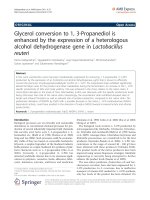
be kept within the tolerance specified in Annex A. (see Figure 1):
a) test velocity, Un;
b) load on the tyre normal to the drum surface,
Lm ;
6. 5 Me asureme nt and re cording
2
Reprodu ced by I H S u n d er l i cen se wi th BSI - U n con trol l ed Copy
© BSI 12-1999
BS AU 5 0 -1 . 3 : 1 993
c) test inflation pressure:
1 ) initial, as defined in
6. 3 ,
a) Remove the tyre from the drum surface.
U , record the input torque,
T , the power, or the test drum deceleration,
2) final, for capped inflation;
b) At the test velocity,
T , the
tyre spindle force, F , the input power, V × A, or
d) the driving torque on the drive shaft,
the deceleration of the test drum/tyre/wheel
whichever applies.
Deceleration method
6. 6. 3
%Ê/%t, depending on the method;
);
e) distance, r (see
;
f) ambient temperature, t
g) test drum radius, R;
n
p
t
t
assembly,
a) Remove the tyre from the test surface.
7. 2 . 1
L
Machine reading
6. 6. 2
b) Record the deceleration of the test drum,
%Ê /%t, and that of the unloaded tyre, %Ê /%t.
amb
o
po
7 D ata interpretation
h) test method chosen;
i) test rim (designation and material) .
7 . 1 Sub traction of parasitic losses
The parasitic losses shall be subtracted as shown
in
7.1 .1 , 7.1 .2
or
7.1 .3.
Skim reading
7.1 .1
Subtract the skim reading from the test
measurement.
Machine reading
7.1 .2
Subtract the machine reading from the test
measurement.
Parasitic losses
7.1 .3
Calculate the parasitic losses,
F , in newtons as
p
where
I
is the test drum inertia in rotation, in
D
R
Ê
kilogram metres squared;
is the test drum surface radius, in metres;
vo
%t
is the test drum angular velocity, without
tyre, in radians per second;
o
is the time increment chosen for the
measurement of the parasitic losses
without tyre, in seconds;
I
T
Figure 1 — Fre e -b ody diagram of tyre /drum
system, assuming no b e aring and
windage losses
6. 6. 1
to
r
po
is the tyre angular velocity, unloaded tyre,
7 . 2 Rolling re sistance calculation
Determine parasitic losses by the procedure given
6. 6. 1
kilogram metres squared;
is the tyre rolling radius, in metres;
in radians per second.
6. 6 Me asure ment of p arasitic losse s
in
R
Ê
is the tyre and wheel inertia in rotation, in
6. 6. 3 .
The net values of driving torque, spindle force,
power or deceleration are to be converted to rolling
Skim reading
resistance,
a) Reduce the load to maintain the tyre at the test
F , expressed in newtons, using the
r
appropriate method, as shown in
7.2.1
to
7.2.4.
velocity without slippage to, for example, 50 N.
b) Record the spindle force,
F , input torque, T ,
p
p
or the power, whichever applies.
c) Record the load on the tyre normal to the drum
surface,
L.
p
© BSI 1 2- 1 999
Reprodu ced by I H S u n d er l i cen se wi th BSI - U n con trol l ed Copy
3
BS AU 5 0-1 .3:1 993
Force method
7.2.1
The rolling resistance,
Annex C gives guidelines and practical examples to
F , in newtons, is calculated
r
with the equation
F = F [1 + (r /R) ]
r
t
8.1 Rolling resistance coefficient
F
r
is the tyre spindle force, in newtons;
t
is the distance from the tyre axis to the
L
drum outer surface under steady- state
conditions, in metres;
is the test drum radius, in metres.
Torque method
7.2.2
The rolling resistance,
F , in newtons, is calculated
r
T
R
= ----
r
=
V
F , in newtons, is calculated
r
V× A
U
3, 6
r
is the rolling resistance, in newtons;
m
is the test load, in newtons.
n
F , in newtons, is calculated
r
kilogram metres squared;
is the test drum surface radius, in metres;
is the time increment chosen for
measurement, in seconds;
is the test drum angular velocity, loaded
tyre, in radians per second;
is the tyre and wheel inertia in rotation, in
T
r
AP
F [1 + K(t
=
r
amb
– 25)]
F
t
is the rolling resistance, in newtons;
is the ambient temperature, in degrees
Celsius;
K
is equal to 0, 01 for car tyres.
8.3 Drum diameter correction
formula:
F Ò KF
r02
r01
with
where
is the test drum inertia in rotation, in
I
F
Test results obtained from different drum diameters
where
v
is the
may be compared by using the following theoretical
with the equation
v
r25
hour.
The rolling resistance,
D
F
rolling resistance at 25 ° C, in newtons:
is the test drum velocity, in kilometres per
Deceleration method
I
using the following equation, where
amb
machine drive, in amperes;
U
then a correction for temperature shall be made
r
is the electric current drawn by the
P
F
L
where
machine drive, in volts;
R
M
F
r
where
r25
is the electrical potential applied to the
A
Ê
F
L
=
is the test drum radius, in metres.
where
R
%t
r
are unavoidable (only temperatures not less
n
7.2.4
C
than 20 ° C not more than 30 ° C are acceptable),
with the equation
r
tyre:
is the input torque, in newton metres;
The rolling resistance,
F
r
If measurements at temperatures other than 25 ° C
Power method
7.2.3
C , is calculated by
dividing the rolling resistance by the load on the
8.2 Temperature correction
where
T
R
The rolling resistance coefficient,
m
with the equation
F
method.
8 Data analysis
L
where
R
measure the moments of inertia for the deceleration
R
R
r
F
1
2
T
r01
F
r02
is the radius of drum 1 , in metres;
is the radius of drum 2, in metres;
is the nominal tyre radius, in metres;
is the rolling resistance value measured on
drum 1 , in newtons;
is the rolling resistance value measured on
drum 2, in newtons.
kilogram metres squared;
is the tyre rolling radius, in metres;
is the tyre aerodynamic torque;
is as defined in 7.1 .3 .
4
Reprodu ced by I H S u n d er l i cen se wi th BSI - U n con trol l ed Copy
© BSI 1 2- 1 999
BS AU 50-1 .3:1 993
Annex A (normative)
Test equipment tolerances
A.1 Purpose
The limits specified in this annex are necessary in
order to achieve suitable levels of repeatable test
results, which can also be correlated among various
test laboratories. These tolerances are not meant to
represent a complete set of engineering
specifications for test equipment: instead, they
should serve as guidelines for achieving reliable test
results.
0,5 km/h for the force method;
— time: ± 0,02 s
— angular velocity: ± 0,2 %
A.4.2 Optional compensation for load /spindle
force interaction and load misalignment
±
NOTE 2 This compensation applies for the force method only.
Compensation of both load/spindle force interaction
(“crosstalk”) and load misalignment may be
accomplished either by recording the spindle force
for both forward and reverse tyre rotation or by
dynamic machine calibration. If spindle force is
recorded for forward and reverse directions (at each
A.2 Test rims
test condition), compensation is achieved by
A.2.1 Width
subtracting the “reverse” value from the “forward”
value and dividing the result by two. If dynamic
The test rim width shall be equal to the
standardized measuring rim. If this is not available, machine calibration is intended, the compensation
then the next wider rim may be chosen. It should be terms may be easily incorporated in the data
reduction.
noted that a change in rim width will result in
different test results.
A.5 Instrumentation accuracy
A.2.2 Runout
The instrumentation used for readout and recording
of test data shall be accurate within the tolerances
Runout shall meet the following criteria:
stated below:
— maximum radial runout: 0,5 mm
— tyre load: ± 10 N
— maximum lateral runout: 0,5 mm
— inflation pressure: ± 1 kPa
A.3 Alignment
— spindle force: ± 0,5 N
Angle deviations are critical to the test results.
— torque input: ± 0,5 N·m
A.3.1 Load application
— distance: ± 1 mm
The direction of tyre loading application shall be
—
electrical power: ± 10 W
kept normal to the test surface and shall pass
through the wheel centre within
— temperature: ± 0,2 °C
— 1 mrad for the force and deceleration methods;
— surface velocity: ± 0,1 km/h (for all methods)
— 5 mrad for the torque and power methods.
— time: ± 0,01 s
A.3.2 Tyre alignment
— angular velocity: ± 0,1 %
A.3.2.1 Camber angle
A.6 Test surface roughness
The plane of the wheel shall be normal to the test The roughness, measured laterally, of the smooth
surface within 2 mrad for all methods.
steel drum surface shall have a maximum
centreline average height value of 6,3 4m.
A.3.2.2 Slip angle
A.7 Tyre spindle bearing friction
The plane of the tyre shall be parallel to the
direction of the test surface motion within 1 mrad When using the machine reading as a method for
for all methods.
determining the parasitic losses, tyre spindle
bearing friction should be regularly verified as being
A.4 Control accuracy
sufficiently small as to be considered negligible
A.4.1 General accuracy
(e.g. a coastdown from 80 km/h to 0 km/h in not less
Exclusive of perturbations induced by the tyre and that 5 min with a freely rotating tyre).
rim non-uniformities, the test equipment shall be
capable of checking the test variables within the
following limits:
— tyre loading: ± 20 N
— inflation pressure: ± 3 kPa
— surface velocity:
± 0,2 km/h for the power, torque and
deceleration methods,
© BSI 12-1999
Reprodu ced by I H S u n d er l i cen se wi th BSI - U n con trol l ed Copy
5
BS AU 50-1 .3:1 993
Annex B (informative)
Optional test conditions
C.2.1 .1
Equipment needed
The arrangement shown in Figure C. 1 requires, in
addition to the drum and its angular encoder:
B.1 Purpose
— a lightweight pulley mounted on low- friction
The rolling resistance of a tyre will vary with
velocity, load and inflation pressure, as well as other
factors. Depending upon the circumstances of
particular tyre applications, it can be useful to
determine the effect of these tyre- related
bearings;
— a weight of known mass,
— suitable wire rope and attachments.
Experimental arrangement
parameters for the individual tyre to be tested. If
C.2.1 .2
such information is desired, the options indicated
See Figure C. 1 .
in B.2 and B.3 are recommended. Unless otherwise
noted, all aspects of the standard test conditions
apply.
m , in the range 50 kg
to 1 00 kg;
C.2.1 .3
Theory
Application of laws of mechanics to the system
shown in Figure C. 1 leads to the following equation:
B.2 Speed sensitivity
Tests are carried out at 50 km/h, 90 km/h
and 1 20 km/h, in sequence (see 5.1 .2 ). A warm- up
period of at least 30 min for the first velocity and at
least 20 min for each successive velocity is required.
B.3 Load and inflation sensitivity
The recommended loads and inflation pressures are
given in Table B. 1 .
A warm- up period of at least 30 min for the first
data point and at least 1 0 min for each successive
data point are required.
m
I
is the mass, in kilograms;
is the pulley inertia, in kilogram metres
P
squared;
r
R
I
is the pulley radius, in metres;
is the drum radius, in metres;
is the drum inertia, in kilogram metres
D
B.4 Textured surface
In cases where a textured drum surface is used
instead of a smooth steel surface, this fact shall be
noted in the test report. The surface texture shall
then be 1 80
where
4m deep (80 grit).
squared;
C
is the friction torque of drum bearings,
in newton metres;
g
is the earth’s gravity equal to 9, 81 m/s 2 ;
%Ê /%t is the angular acceleration or
D
deceleration.
Table B.1
Tyre load as a
Test inflation pressure:
NOTE 3
percentage of
standardized pressure,
neglected.
maximum load
modified:
50
+ 70 kPa, regulated
50
– 30 kPa, regulated
90
+ 70 kPa, regulated
90
– 30 kPa, regulated
The friction torque of pulley bearings,
c, can be
Annex C (informative)
Measurement methods of moment of
inertia for drum and tyre assembly —
Deceleration method
C.1 Limitation
The methods presented here should be considered
only as guidelines or practical examples of methods
used to measure moments of inertia by the
deceleration method to achieve reliable test results.
C.2 Test drum inertia
C.2.1
Measurement method
6
Reprodu ced by I H S u n d er l i cen se wi th BSI - U n con trol l ed Copy
Figure C.1 — Arrangement
© BSI 1 2- 1 999
BS AU 50-1 .3:1 993
C.2.1 .4
Method
m, is released, the angular
When the mass,
acceleration is measured through the angular
encoder fitted to the drum axle (and otherwise used
to measure drum decelerations).
The friction torque,
C, of drum bearings can also be
measured, provided that the rope can be separated
from the drum once mass,
m, has given sufficient
C.3.1 .2
Theory
Equation of free movement of pendulum, if
Ú is the
angle from equilibrium:
I
d
0
2
d
t
Ú + KÚ
2
= 0
Natural oscillation period,
T:
0
momentum to the drum, for the subsequent drum
deceleration is directly related to
I
D
%Ê D
%t
=
dec
C by:
C
where
Ú
where the values are as defined C.2.1 .3 .
C.2.2
Determination method
The drum inertia is estimated by calculation.
The drum inertia,
I , in kilogram metres squared, is
D
determined by the summation of the inertia of each
drum part (flange, disc, reinforced rib):
I
D
=
I+I +I
f
d
t
I
is the period of time, in seconds;
is the torsion pendulum inertia, in
0
kilogram metres squared;
K
is the spring constant.
C.3.1 .3
Method
Measurement of oscillation periods, with the tyre
T , and without, T , can be used to give
I.
K T – T
assembly,
r
1
0
the tyre assembly inertia,
where
I
I
I
is the angle of oscillation, in radians;
f
is the drum flange inertia;
d
is the drum disc inertia;
r
is the reinforced rib inertia;
all values being expressed in kilogram metres
I
T
=
4
C.3.2
;
2
2
2
1
0
T
Bifilar pendulum (rope) method
Tyre inertia can be obtained by the period time of
squared.
twisted oscillation of a tyre hanging from two steel
C.3 Tyre assembly inertia
ropes of exactly the same length (see Figure C. 3) .
C.3.1
Spring method
C.3.1 .1
Equipment needed
Torsion pendulum of inertia
K (see Figure C. 2) .
I
0
and spring constant
Figure C.2 — Spring method
Figure C.3 — Bifilar pendulum (rope)
method
C.3.2.1
Theory
The tyre inertia,
I , in kilogram metres squared, is
T
determined by
© BSI 1 2- 1 999
Reprodu ced by I H S u n d er l i cen se wi th BSI - U n con trol l ed Copy
7
BS AU 5 0-1 .3:1 993
I
T
Ù ×
2
=
Wab
4
;
2
h
where
Ù
W
a
C .3.2.2
Method
The time p eriod,
Ù
, of the twis ted os cillation of a tyre
is meas ured, and tyre inertia can b e calculated from
the equation given in
C.3.2.1 .
is the oscillation p eriod, in s econds ;
is the tyre and wheel weight, in newtons ;
is the distance b etween p oints A and B, in
metres ;
b
is the dis tance b etween p oints C and D , in
metres ;
h
is the vertical dis tance b etween lines AB
and C D , in metres .
8
Reprodu ced by I H S u n d er l i cen se wi th BSI - U n con trol l ed Copy
© BS I 1 2 - 1 99 9
blank
Reprodu ced by I H S u n d er l i cen se wi th BSI - U n con trol l ed Copy
BS AU
5 0-1 .3:1 993
ISO 8767:1 992
BSI — British Standards Institution
BS I is the indep endent national b ody res p ons ib le for p rep aring
Britis h S tandards . It p res ents the UK view on s tandards in E urop e and at the
international level. It is incorp orated b y Royal C harter.
Revisions
Britis h S tandards are up dated b y amendment or revis ion. Us ers of
Britis h S tandards should make s ure that they p oss es s the latest amendments or
editions .
It is the constant aim of BS I to imp rove the quality of our p roducts and services .
We would b e grateful if anyone finding an inaccuracy or amb iguity while us ing
this Britis h S tandard would inform the S ecretary of the technical committee
res p ons ib le, the identity of which can b e found on the inside front cover.
Tel: 02 0 89 96 90 00. Fax: 02 0 89 96 7 40 0 .
BS I offers memb ers an individual up dating s ervice called PLUS which ens ures
that s ub s crib ers automatically receive the lates t editions of s tandards .
Buying standards
O rders for all BS I, international and foreign s tandards p ub lications s hould b e
addres s ed to C us tomer S ervices. Tel: 0 2 0 899 6 9 00 1 . Fax: 0 2 0 899 6 7001 .
In res p ons e to orders for international standards , it is BS I p olicy to sup p ly the
BS I imp lementation of thos e that have b een p ub lis hed as Britis h S tandards,
unless otherwis e requested.
Information on standards
BS I p rovides a wide range of information on national, E urop ean and
international standards through its Lib rary and its Technical H elp to E xp orters
S ervice. Various BS I electronic information s ervices are also availab le which give
details on all its p roducts and s ervices . C ontact the Information C entre.
Tel: 02 0 89 96 71 1 1 . Fax: 02 0 89 96 7 048.
S ub s crib ing memb ers of BS I are kep t up to date with s tandards develop ments
and receive sub s tantial discounts on the p urchase p rice of s tandards. For details
of thes e and other b enefits contact Memb ership Adminis tration.
Tel: 02 0 89 96 70 02 . Fax: 02 0 89 96 7 00 1 .
Copyright
C op yright s ub s is ts in all BS I p ub lications . BS I als o holds the cop yright, in the
UK, of the p ub lications of the international s tandardization b odies . E xcep t as
p ermitted under the C op yright, D es igns and Patents Act 1 988 no extract may b e
rep roduced, s tored in a retrieval s ystem or transmitted in any form or b y any
means – electronic, p hotocop ying, recording or otherwis e – without p rior written
p ermis s ion from BS I.
This does not p reclude the free us e, in the cours e of imp lementing the standard,
of necess ary details such as s ymb ols, and size, typ e or grade designations. If thes e
details are to b e used for any other p urp os e than imp lementation then the p rior
written p ermiss ion of BS I must b e ob tained.
If p ermis sion is granted, the terms may include royalty p ayments or a licensing
agreement. D etails and advice can b e ob tained from the C op yright Manager.
BS I
3 89 C his wick H igh Road
London
W4 4AL
Reprodu ced by I H S u n d er l i cen se wi th BSI - U n con trol l ed Copy
Tel: 02 0 89 96 70 7 0.