C200H-TC emperature Control Units W124 e1 5
Bạn đang xem bản rút gọn của tài liệu. Xem và tải ngay bản đầy đủ của tài liệu tại đây (198.7 KB, 51 trang )
C200H Temperature Sensor Unit
Operation Manual
Revised April 2000
!
!
!
v
Notice:
OMRON products are manufactured for use according to proper procedures by a qualified operator
and only for the purposes described in this manual.
The following conventions are used to indicate and classify precautions in this manual. Always heed
the information provided with them. Failure to heed precautions can result in injury to people or dam-
age to property.
DANGER Indicates an imminently hazardous situation which, if not avoided, will result in death or
serious injury.
WARNING Indicates a potentially hazardous situation which, if not avoided, could result in death or
serious injury.
Caution Indicates a potentially hazardous situation which, if not avoided, may result in minor or
moderate injury, or property damage.
OMRON Product References
All OMRON products are capitalized in this manual. The word “Unit” is also capitalized when it refers
to an OMRON product, regardless of whether or not it appears in the proper name of the product.
The abbreviation “Ch,” which appears in some displays and on some OMRON products, often means
“word” and is abbreviated “Wd” in documentation in this sense.
The abbreviation “PC” means Programmable Controller and is not used as an abbreviation for any-
thing else.
Visual Aids
The following headings appear in the left column of the manual to help you locate different types of
information.
Note Indicates information of particular interest for efficient and convenient operation
of the product.
1, 2, 3 1. Indicates lists of one sort or another, such as procedures, checklists, etc.
OMRON, 1989
All rights reserved. No part of this publication may be reproduced, stored in a retrieval system, or transmitted, in any
form, or by any means, mechanical, electronic, photocopying, recording, or otherwise, without the prior written permis-
sion of OMRON.
No patent liability is assumed with respect to the use of the information contained herein. Moreover, because OMRON is
constantly striving to improve its high-quality products, the information contained in this manual is subject to change
without notice. Every precaution has been taken in the preparation of this manual. Nevertheless, OMRON assumes no
responsibility for errors or omissions. Neither is any liability assumed for damages resulting from the use of the informa-
tion contained in this publication.
vii
TABLE OF CONTENTS
PRECAUTIONS xi. . . . . . . . . . . . . . . . . . . . . . . . . . . . . . . . .
1 Intended Audience xii. . . . . . . . . . . . . . . . . . . . . . . . . . . . . . . . . . . . . . . . . . . . . . . . . . . . . . . . . . .
2 General Precautions xii. . . . . . . . . . . . . . . . . . . . . . . . . . . . . . . . . . . . . . . . . . . . . . . . . . . . . . . . . .
3 Safety Precautions xii. . . . . . . . . . . . . . . . . . . . . . . . . . . . . . . . . . . . . . . . . . . . . . . . . . . . . . . . . . .
4 Operating Environment Precautions xiii. . . . . . . . . . . . . . . . . . . . . . . . . . . . . . . . . . . . . . . . . . . . .
5 Application Precautions xiii. . . . . . . . . . . . . . . . . . . . . . . . . . . . . . . . . . . . . . . . . . . . . . . . . . . . . . .
SECTION 1
Introduction 1. . . . . . . . . . . . . . . . . . . . . . . . . . . . . . . . . . . . .
1-1 Nomenclature and Features 2. . . . . . . . . . . . . . . . . . . . . . . . . . . . . . . . . . . . . . . . . . . . . . . .
1-2 System Configuration 4. . . . . . . . . . . . . . . . . . . . . . . . . . . . . . . . . . . . . . . . . . . . . . . . . . . . .
SECTION 2
Wiring 7. . . . . . . . . . . . . . . . . . . . . . . . . . . . . . . . . . . . . . . . . .
2-1 Setup 8. . . . . . . . . . . . . . . . . . . . . . . . . . . . . . . . . . . . . . . . . . . . . . . . . . . . . . . . . . . . . . . . . .
SECTION 3
I/O Allocation 11. . . . . . . . . . . . . . . . . . . . . . . . . . . . . . . . . . . .
3-1 Word Allocation 12. . . . . . . . . . . . . . . . . . . . . . . . . . . . . . . . . . . . . . . . . . . . . . . . . . . . . . . . .
3-2 Bit Allocation 13. . . . . . . . . . . . . . . . . . . . . . . . . . . . . . . . . . . . . . . . . . . . . . . . . . . . . . . . . . .
SECTION 4
Settings and Displays 15. . . . . . . . . . . . . . . . . . . . . . . . . . . . . .
4-1 Temperature Specification Settings 16. . . . . . . . . . . . . . . . . . . . . . . . . . . . . . . . . . . . . . . . . .
4-2 Temperature Data Display 18. . . . . . . . . . . . . . . . . . . . . . . . . . . . . . . . . . . . . . . . . . . . . . . . .
Appendices
A. Troubleshooting 23. . . . . . . . . . . . . . . . . . . . . . . . . . . . . . . . . . . . . . . . . . . . . . . . . . . . . . . . .
B. Standard Models 25. . . . . . . . . . . . . . . . . . . . . . . . . . . . . . . . . . . . . . . . . . . . . . . . . . . . . . . . .
C. Specifications 27. . . . . . . . . . . . . . . . . . . . . . . . . . . . . . . . . . . . . . . . . . . . . . . . . . . . . . . . . . .
D. Table of Temperature-Sensing Elements 29. . . . . . . . . . . . . . . . . . . . . . . . . . . . . . . . . . . . . .
E. Using the C200H Temperature Sensor Unit with CS1-series PCs 37. . . . . . . . . . . . . . . . . . .
Glossary 39. . . . . . . . . . . . . . . . . . . . . . . . . . . . . . . . . . . . . . . .
Index 47. . . . . . . . . . . . . . . . . . . . . . . . . . . . . . . . . . . . . . . . . . .
Revision History 49. . . . . . . . . . . . . . . . . . . . . . . . . . . . . . . . . .
ix
About this Manual:
This manual describes the installation and operation of the C200H Temperature Sensor Unit and includes
the sections described below.
Please read this manual carefully and be sure you understand the information provided before attempting
to install and operate the C200H Temperature Sensor Unit.
Section 1 provides an introduction to the C200H Temperature Sensor Unit and includes details on no-
menclature and functions as well as the system configuration.
Section 2 explains the wiring procedure required when setting up the Unit.
Section 3 gives details on the word and bit allocations for the Unit.
Section 4 explains how to make temperature settings and how to read the display.
Appendices, a Glossary, and an Index are also included.
WARNING Failure to read and understand the information provided in this manual may result in
personal injury or death, damage to the product, or product failure. Please read each
section in its entirety and be sure you understand the information provided in the section
and related sections before attempting any of the procedures or operations given.
!
xi
PRECAUTIONS
This section provides general precautions for using the C200H Temperature Sensor Unit and related devices.
The information contained in this section is important for the safe and reliable application of the C200H Temperature
Sensor Unit. You must read this section and understand the information contained before attempting to set up or oper-
ate the C200H Temperature Sensor Unit.
1 Intended Audience xii. . . . . . . . . . . . . . . . . . . . . . . . . . . . . . . . . . . . . . . . . . . . . . . . . . . . . . . . . . .
2 General Precautions xii. . . . . . . . . . . . . . . . . . . . . . . . . . . . . . . . . . . . . . . . . . . . . . . . . . . . . . . . . .
3 Safety Precautions xii. . . . . . . . . . . . . . . . . . . . . . . . . . . . . . . . . . . . . . . . . . . . . . . . . . . . . . . . . . .
4 Operating Environment Precautions xiii. . . . . . . . . . . . . . . . . . . . . . . . . . . . . . . . . . . . . . . . . . . . .
5 Application Precautions xiii. . . . . . . . . . . . . . . . . . . . . . . . . . . . . . . . . . . . . . . . . . . . . . . . . . . . . . .
!
!
!
!
!
3Safety Precautions
xii
1 Intended Audience
This manual is intended for the following personnel, who must also have knowl-
edge of electrical systems (an electrical engineer or the equivalent).
• Personnel in charge of installing FA systems.
• Personnel in charge of designing FA systems.
• Personnel in charge of managing FA systems and facilities.
2 General Precautions
The user must operate the product according to the performance specifications
described in the relevant manuals.
Before using the product under conditions which are not described in the manual
or applying the product to nuclear control systems, railroad systems, aviation
systems, vehicles, combustion systems, medical equipment, amusement ma-
chines, safety equipment, and other systems, machines, and equipment that
may have a serious influence on lives and property if used improperly, consult
your OMRON representative.
Make sure that the ratings and performance characteristics of the product are
sufficient for the systems, machines, and equipment, and be sure to provide the
systems, machines, and equipment with double safety mechanisms.
This manual provides information for programming and operating the Unit. Be
sure to read this manual before attempting to use the Unit and keep this manual
close at hand for reference during operation.
WARNING It is extremely important that a PC and all PC Units be used for the specified
purpose and under the specified conditions, especially in applications that can
directly or indirectly affect human life. You must consult with your OMRON
representative before applying a PC system to the above-mentioned
applications.
3 Safety Precautions
WARNING Do not attempt to take any Unit apart while the power is being supplied. Doing so
may result in electric shock.
WARNING Do not touch any of the terminals or terminal blocks while the power is being
supplied. Doing so may result in electric shock.
WARNING Do not attempt to disassemble, repair, or modify any Units. Any attempt to do so
may result in malfunction, fire, or electric shock.
WARNING Provide safety measures in external circuits (i.e., not in the Programmable
Controller), including the following items, in order to ensure safety in the system
if an abnormality occurs due to malfunction of the PC or another external factor
affecting the PC operation. Not doing so may result in serious accidents.
• Emergency stop circuits, interlock circuits, limit circuits, and similar safety
measures must be provided in external control circuits.
• The PC will turn OFF all outputs when its self-diagnosis function detects any
error or when a severe failure alarm (FALS) instruction is executed. As a coun-
termeasure for such errors, external safety measures must be provided to en-
sure safety in the system.
!
!
!
!
5Application Precautions
xiii
• The PC outputs may remain ON or OFF due to deposition or burning of the
output relays or destruction of the output transistors. As a countermeasure for
such problems, external safety measures must be provided to ensure safety in
the system.
• When the 24-VDC output (service power supply to the PC) is overloaded or
short-circuited, the voltage may drop and result in the outputs being turned
OFF. As a countermeasure for such problems, external safety measures must
be provided to ensure safety in the system.
4 Operating Environment Precautions
Caution Do not operate the control system in the following locations:
• Locations subject to direct sunlight.
• Locations subject to temperatures or humidity outside the range specified in
the specifications.
• Locations subject to condensation as the result of severe changes in tempera-
ture.
• Locations subject to corrosive or flammable gases.
• Locations subject to dust (especially iron dust) or salts.
• Locations subject to exposure to water, oil, or chemicals.
• Locations subject to shock or vibration.
Caution Take appropriate and sufficient countermeasures when installing systems in the
following locations:
• Locations subject to static electricity or other forms of noise.
• Locations subject to strong electromagnetic fields.
• Locations subject to possible exposure to radioactivity.
• Locations close to power supplies.
Caution The operating environment of the PC system can have a large effect on the lon-
gevity and reliability of the system. Improper operating environments can lead to
malfunction, failure, and other unforeseeable problems with the PC system. Be
sure that the operating environment is within the specified conditions at installa-
tion and remains within the specified conditions during the life of the system.
5 Application Precautions
Observe the following precautions when using the PC system.
WARNING Always heed these precautions. Failure to abide by the following precautions
could lead to serious or possibly fatal injury.
• Always ground the system to 100 Ω or less when installing the Units. Not con-
necting to a ground of 100 Ω or less may result in electric shock.
• Always turn OFF the power supply to the PC before attempting any of the fol-
lowing. Not turning OFF the power supply may result in malfunction or electric
shock.
• Mounting or dismounting I/O Units, CPU Units, Memory Units, or any other
Units.
• Assembling the Units.
• Setting DIP switches or rotary switches.
• Connecting cables or wiring the system.
• Connecting or disconnecting the connectors.
!
5Application Precautions
xiv
Caution Failure to abide by the following precautions could lead to faulty operation of the
PC or the system, or could damage the PC or PC Units. Always heed these pre-
cautions.
• Fail-safe measures must be taken by the customer to ensure safety in the
event of incorrect, missing, or abnormal signals caused by broken signal lines,
momentary power interruptions, or other causes.
• Always use the power supply voltages specified in this manual. An incorrect
voltage may result in malfunction or burning.
• Take appropriate measures to ensure that the specified power with the rated
voltage and frequency is supplied. Be particularly careful in places where the
power supply is unstable. An incorrect power supply may result in malfunction.
• Install external breakers and take other safety measures against short-circuit-
ing in external wiring. Insufficient safety measures against short-circuiting may
result in burning.
• Do not apply voltages to the Input Units in excess of the rated input voltage.
Excess voltages may result in burning.
• Do not apply voltages or connect loads to the Output Units in excess of the
maximum switching capacity. Excess voltage or loads may result in burning.
• Disconnect the functional ground terminal when performing withstand voltage
tests. Not disconnecting the functional ground terminal may result in burning.
• Be sure that all the mounting screws, terminal screws, and cable connector
screws are tightened to the torque specified in this manual. Incorrect tighten-
ing torque may result in malfunction.
• Leave the label attached to the Unit when wiring. Removing the label may re-
sult in malfunction if foreign matter enters the Unit.
• Remove the label after the completion of wiring to ensure proper heat dissipa-
tion. Leaving the label attached may result in malfunction.
• Double-check all wiring and switch settings before turning ON the power sup-
ply. Incorrect wiring may result in burning.
• Wire correctly. Incorrect wiring may result in burning.
• Mount Units only after checking terminal blocks and connectors completely.
• Be sure that the terminal blocks, Memory Units, expansion cables, and other
items with locking devices are properly locked into place. Improper locking
may result in malfunction.
• Check the user program for proper execution before actually running it on the
Unit. Not checking the program may result in an unexpected operation.
• Confirm that no adverse effect will occur in the system before attempting any of
the following. Not doing so may result in an unexpected operation.
• Changing the operating mode of the PC.
• Force-setting/force-resetting any bit in memory.
• Changing the present value of any word or any set value in memory.
• Resume operation only after transferring to the new CPU Unit the contents of
the DM Area, HR Area, and other data required for resuming operation. Not
doing so may result in an unexpected operation.
• Do not pull on the cables or bend the cables beyond their natural limit. Doing
either of these may break the cables.
• Do not place objects on top of the cables or other wiring lines. Doing so may
break the cables.
• Use crimp terminals for wiring. Do not connect bare stranded wires directly to
terminals. Connection of bare stranded wires may result in burning.
• When replacing parts, be sure to confirm that the rating of a new part is correct.
Not doing so may result in malfunction or burning.
5Application Precautions
xv
• Before touching a Unit, be sure to first touch a grounded metallic object in order
to discharge any static built-up. Not doing so may result in malfunction or dam-
age.
1
SECTION 1
Introduction
1-1 Nomenclature and Features 2. . . . . . . . . . . . . . . . . . . . . . . . . . . . . . . . . . . . . . . . . . . . . . . .
1-2 System Configuration 4. . . . . . . . . . . . . . . . . . . . . . . . . . . . . . . . . . . . . . . . . . . . . . . . . . . . .
2
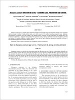
1-1 Nomenclature and Features
The Temperature Sensor Unit detects temperatures and sends the resultant
BCD (Binary Coded Decimal) data to the PC (Programmable Controller). This
data can be further manipulated and transferred to other I/O Units for ex-
tended system control.
The C200H Temperature Sensor Unit is available in four models. The
C200H-TS001/002 are for use with thermocouples, and can be used with K
(CA), J (IC) and L (Fe-CuNi) thermocouples. The C200H-TS101/102 are for
use with platinum resistance sensors.
The Unit has the following components:
Front Panel
Indicator
panel
Unit no.
selector
Input terminal
block. Refer to
Section 2 Wiring
for details.
Cold- junction
compensating
resistor
C200H-TS001/002
(Thermocouple)
C200H-TS101/102
(Platinum RTD)
Indicator
panel
Unit no.
selector
Input termi-
nal block.
Refer to
Section 2
Wiring for
details.
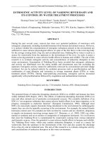
Unit Number Selector
(7)
(9)
(5)
(1)
(3)
0
8
6
4
2
The arrow on the selector indicates the unit number. Use a standard screw-
driver to rotate the switch and set the desired unit number. Be sure to set dif-
ferent unit numbers from those of other Special I/O Units connected to the
same PC. Otherwise, an “I/O Unit Over” error is generated and the Unit will
not operate properly. IR word numbers are assigned as shown in the follow-
ing table.
Nomenclature and Features Section 1-1
3
Unit no. IR word
0 100 through 109
1 110 through 119
2 120 through 129
3 130 through 139
4 140 through 149
5 150 through 159
6 160 through 169
7 170 through 179
8 180 through 189
9 190 through 199
Indicator panel There are two LEDs in the indicator panel, which function as follows:
Indicator Color Function
RUN Green Lit during normal operation. Unlit during errors.
BROKEN
WIRE
Red Lit when input is disconnected. Blinks when
data is outside of set range.
DIP Switch Setting
C200H-TS001/002
1234ON
2
0
1 No. of Input Points
0 0 4 input points (Inputs
1 through 4)
01
10
11
1 input point (Input 1)
2 input points (Inputs
1 and 2)
Not Used
3 Function
Either K (CA) (0° through 400°C), J
(IC) (0° through 300°C), or L (Fe-
CuNi) (0° through 300°C). Once this
pin has been set to ON, this setting
becomes invalid and the tempera-
ture must be set through the PC
program.
1 Set the temperature depending on
PC program.
4
0
1
Function
K ( CA)
J (IC), L(Fe-
CuNi)
OFF: 0
ON: 1
Number of Input Points Temperature Selector Sensor Selector
All switches are OFF before shipment from the factory.
The temperature specifications must be set identically for all four points.
These points cannot be used for different thermocouples or with different
temperature specifications.
The cold-junction compensating resistor connected to the C200H-TS001/002
terminal block (for the thermocouple) has been preset to the Unit’s internal
circuits. Do not remove or replace it. If it is necessary to remove it, when
reattaching, confirm that the number marked on the resistor matches the
number on the Unit, as shown in the following diagram. The output tempera-
ture data may be incorrect if the numbers do not match.
Nomenclature and Features Section 1-1
4
Terminal
block
Cold-junc-
tion com-
pensating
resistor
These two
numbers
must
match
DIP Switch Setting
C200H-TS101/102
1234ON
2
0
1 No. of Input Points
0 0 4 input points (Inputs
1 through 4)
01
10
11
1 input point (Input 1)
2 input points (Inputs
1 and 2)
Not Used
3 Function
J Pt (0° through 100°C)/Pt (0°
through 100°C). Once this pin is set
to ON, this setting becomes invalid
and the temperature must be set
through the PC program.
1 Set the temperature depending on
PC program.
OFF: 0
ON: 1
Number of Input Points Temperature Selector Not Used
All switches are set to OFF before shipment from the factory.
1-2 System Configuration
The Special I/O Units are not allocated the word number of the slot they are
mounted to. They are allocated word numbers according to the unit number
setting on the front panel (refer to page 2).
If possible, avoid mounting the Temperature Sensor Units in either of the two
rightmost CPU Rack slots. However, if this is unavoidable, use one of the
Programming Console Base Units (C200H-BP001 or C200H-BP002) when
mounting peripheral devices to the PC.
No Special I/O Units can be mounted on a C200H Slave Rack connected to a
Master on a PC other than a C200H.
The thermocouple or RTD registers the temperature and sends the data
through the Temperature Sensor Unit to the PC in 4-digit BCD. After the PC
processes this data, the data can be output to a display, or used for control-
ling system devices.
System Configuration Section 1-2
5
fuel
Display
Temperature Sensor Unit
C200H-TS001/002/101/102
Output Unit
High-Density and Multiplex
I/O Unit C200H-OD215
CPUs
C200H-
CPU01-E/03-E/11-E
•
Temperature-
sensing element
A maximum of 10 Special I/O Units (including the PC Link Units) can be
mounted on the CPU Rack, Expansion I/O Rack, or Slave Rack. However,
the maximum current supplied or consumed may limit the actual number of
I/O Units that can be connected. Refer to the C200H Installation Guide for
maximum current levels. Note that the specific limit, resulting from data trans-
mission, placed on the Slave Rack is as shown in the following table.
The number of Special I/O Units that can be mounted on a Slave Rack is lim-
ited. The table below shows the maximum number of Special I/O Units that
can be mounted to one Slave Rack.
A B C D
Maximum number
of High-Speed
Counter Units,
Position Control
Units
(NC111/NC112),
ASCII Units,
Analog I/O Units,
and ID Sensor
Units
Maximum number
of High-Density
and Multiplex I/O
Units.
Maximum number
of Voice and
Temperature
Sensor Units.
Maximum number
of Position Control
Units (NC211)
4 Units 8 Units 6 Units 2 Units
Note 1. When using a combination of Units, use the following formula:
3A+B+2C+6D≤12 and, A+B+C+D≤8
2. These Units can be used on other Racks, but the total number cannot
exceed 10.
Mounting Temperature
Sensor Units
Special I/O Units on Slave
Racks
System Configuration Section 1-2
7
SECTION 2
Wiring
2-1 Setup 8. . . . . . . . . . . . . . . . . . . . . . . . . . . . . . . . . . . . . . . . . . . . . . . . . . . . . . . . . . . . . . . . . .
!
8
2-1 Setup
External Connections
B0
B1
B4
B5
B6
B7
B8
B3
A1
A2
A3
A4
A5
A6
A7
A8
B2
R
0
A0
+
–
+
–
+
–
+
–
Input 1
Input 2
Input 3
B9
Input 4
B0
B1
B8
B3
B4
B5
B6
B7
A1
A2
A3
A4
A5
A6
A7
A8
B9
B2
A0
Input 1
Input 2
Input 3
Input 4
A
B
B
′
A
B
B′
A
B
B′
A
B
B
′
C200H-TS001/002 C200H-TS101/102
Caution R
0
: Cold-junction compensating resistor
The cold-junction compensating resistor connecting terminals B4 and B5 on the
C200H-TS001/002 is fully integrated in the internal circuitry of the Unit and
serves to maintain accuracy. Be careful not to remove this resistor and be sure
the screws are always tight.
Unused Input Terminals For TS001/002 (thermocouple input), short the positive and negative poles of
the thermocouple inputs (for example, terminals A8 and B8 in Input 4).
For TS101/102 (platinum RTD input), short the B and B′ terminals (for exam-
ple, terminals A8 and B9 for Input 4), and connect a 100 Ω (1/8 W minimum)
resistor between terminals A and B. (For example, A8 and B8 for input 4.)
Removable Terminal Block Connections
When Using Solderless Crimp Leads
Use M3.5 screws (with self-rising pressure plates) for mounting solderless
crimp terminals.
7 mm max.
7 mm max.
Setup Section 2-1
9
Soldered leads
Carefully tin the 5- to 7-mm exposed end of the lead wire.
+
5 to 7 mm
10 mm
Tighten the screws to a
torque of 0.8 N S m.
Wiring Notes To avoid influence from induced noise, keep the input signal wires (compen-
sating wires or lead wires) away from the power source line or load line by at
least 300 mm. Also be sure not to lay them parallel to, or in the same cable
as, the power line. Using shield wires in separated ducts or pipes is also an
effective way to reduce influence from noise. Attach surge absorbers or noise
filters to peripheral devices that generate noise (in particular, devices that
possess inductance components, such as motors, transistors, solenoids, or
magnet coils). Install away from devices that generate strong, high-frequency
waves or that generate surges.
Connect the thermocouples with the compensating wires as shown in the
following diagram. Connect platinum RTDs with lead wires of low resistance
(for example, copper wires). Make the three lead wires extending from the
platinum RTDs equal in length. Do not short-circuit the B wire and B’ wire
near the terminal block connector, because it causes measurement errors.
Input Signal Wire Extension The input signal wire should be as short as possible so that the effect of out-
side noise is minimized. The following table has more information on type
and length of the signal wire.
Sensor-Input Wire Configuration Maximum
Extension Length
K (CA) Compensating conductor
WX-H, WX-H6
0.3 mm
2
x 7 leads 80 m
J (IC) Compensating conductor
JX-H, JX-H6
0.3 mm
2
x 7 leads 70 m
L (Fe-CuNi) Compensating conductors
JX
0.3 mm
2
x 7 leads 70 m
JPt 100 ΩPt
100
Ω
Copper wire 0.5 mm
2
120 m
Setup Section 2-1
11
SECTION 3
I/O Allocation
3-1 Word Allocation 12. . . . . . . . . . . . . . . . . . . . . . . . . . . . . . . . . . . . . . . . . . . . . . . . . . . . . . . . .
3-2 Bit Allocation 13. . . . . . . . . . . . . . . . . . . . . . . . . . . . . . . . . . . . . . . . . . . . . . . . . . . . . . . . . . .
12
3-1 Word Allocation
The unit number setting (on the front panel of the Temperature Sensor Unit)
determines the words allocated to the Unit. Ten words are assigned to any
given Special I/O Unit, but only six words are actually used by the Tempera-
ture Sensor Unit. The following figure shows which words are available ac-
cording to the unit number setting.
Unit 0
Unit 1
Unit 2
Unit 3
Unit 4
Unit 5
Unit 6
Unit 7
Unit 8
Unit 9
100 through 109
120 through 129
130 through 139
140 through 149
150 through 159
160 through 169
170 through 179
180 through 189
190 through 199
110 through 119
Each time the PC data
is refreshed, output
data is written from the
PC to the Temperature
Sensor, then input data
is read from the Tem-
perature Sensor to the
PC.
Output refresh
Input refresh
Word n
Words n+1
through
n+5
Only six words are
used. Words n+6
through n+9 are avail-
able as work bits
n = 100 + 10 x unit no.
PCs IR area
Note When setting a unit number, be sure not to select the same number used for
another Special I/O Unit. Otherwise, an “I/O UNIT OVER” error is generated
and the Sensor Unit will not operate properly.
Word Allocation Section 3-1
13
3-2 Bit Allocation
Direction Word Bit
no. 15 14 13 12 11 10 09 08 07 06 05 04 03 02 01 00
Output n Tempera-
ture speci-
fication
Temperature specification
code no.: 00 through 25
Data
hold
enable x 10
1
x 10
0
Input n + 1 Code
0: positive
Conversion data of Input 1
1: negative x 10
3
x 10
2
x 10
1
x 10
0
n + 2 Code
0: positive
Conversion data of Input 2
1: negative x 10
3
x 10
2
x 10
1
x 10
0
n + 3 Code
0: positive
Conversion data of Input 3
1: negative x 10
3
x 10
2
x 10
1
x 10
0
n + 4 Code
0: positive
Conversion data of Input 4
1: negative x 10
3
x 10
2
x 10
1
x 10
0
n + 5
Running
Temperature specification
code no.: 00 through 25
Data
inval-
id
Stand
by for
Memory
error
Disconnection
detected
Setting
error
x 10
1
x 10
0
set-
ting
Input
4
Input
3
Input
2
Input
1
Note n = 100 + 10 x unit no.
The four words from words n+6 through n+9 can be used as work bits. Refer
to the C200H Operation Manual for details.
IR Bit Allocation
IR Name Function
Word Bit
Output n 00 Data hold When this bit is turned ON, conversion of the temperature input
data is stopped and data is returned to its status just prior to turning the
bit ON. When this bit is turned OFF, the temperature input data is
converted to BCD data in cycles.
01
through
07
Always turned OFF.
08
through
13
Temperature
specification
code number
These bits specify the temperature specification code number of the
temperature sensing element used in the Unit. A total of 41 code
numbers (thermocouple K (CA) = 11, thermocouple J (IC) = 4, L(Fe-CuNi)
= 4, platinum RTD JPt = 11, platinum RTD Pt= 11 numbers) can be
specified in 2-digit BCD from 00 through 25. (Refer to pages 3 and 16 for
details.) The temperature specification code number becomes valid after
the temperature specification setting flag (word n bit 15) is turned ON.
14 Not used. Always turned OFF.
15 Temperature
specification
enable
When this bit is turned ON, the temperature specification code number
specified for word n bits 08 through 13 becomes valid. Be sure to confirm
beforehand that the temperature specification switch (pin 3) on the back
panel has been set to the ON position and that the setting standby flag
(word n+5 bit 06) has also been turned ON. Otherwise the code number
is invalid.
Bit Allocation Section 3-2
14
IR FunctionName
Word Bit
Input n + 1 00
through
15
Input 1
conversion
0
1
+
–
x 10
3
x 10
2
x 10
1
x 10
0
15 00
The temperature input data
of input 1 is displayed in
BCD.
n + 2 00
through
15
Input 2
conversion
0
1
+
–
x 10
3
x 10
2
x 10
1
x 10
0
15 00
The temperature input data
of input 2 is displayed in
BCD.
n + 3 00
through
15
Input 3
conversion
x 10
3
x 10
2
x 10
1
x 10
0
15 00
The temperature input data
of input 3 is displayed in
BCD.
0
1
+
–
n + 4 00
through
15
Input 4
conversion data
0
1
+
–
x 10
3
x 10
2
x 10
1
x 10
0
15 00
The temperature input data
of input 3 is displayed in
BCD.
n + 5 00 Setting Error This bit turns ON when the specified temperature specification code
number (word n bits 08 through 13) results in one of the following: 1) a
figure above 26; or 2) the temperature sensing element corresponds to a
different specified code number than the one actually connected to the
Temperature Sensor Unit. For example, if pin 4 is set for K(CA) and the
temperature specification code number is set to 11-25, a setting error is
generated.
01 Input 1
Discon- If a disconnection is detected in one of the inputs, the bit corresponding
02 Input 2
nection to that particular input turns ON. The conversion data of the word
03 Input 3
de-
tected
corresponding to the disconnected input (words n+1 through n+4)
becomes “E039.”
04 Input 4
tected becomes “E039.”
05 Memory error Whenever an error occurs in the Temperature Sensor’s internal memory
(the memory storing the conversion data from each of the four inputs),
this bit turns ON.
06 Setting standby This bit keeps the setting of the temperature specification code number
on standby. After the temperature specification switch (pin 3) on the back
panel is set to the ON position, and while the power supply is ON or
during Restart, this bit remains ON until the setting is completed. When
setting the temperature specification, turn the temperature specification
setting flag (word n bit 15) ON. Refer to page 17 Temperature
specification setting flag.
07 Data invalid After the power supply is turned ON, or after restart, the conversion data
remains unstable for several seconds; during this period, this bit turns
ON. Once all the data stabilizes, the bit turns OFF. While this bit is OFF,
program with the conversion data from words n+1 through n+3. Refer to
page 21 for conversion data listing.
08
through
13
Temperature
specification
code number
These bits pinpoint the current settings of the temperature specification
code number and represent the confirmation area (00 through 25).
14 Not used
15 Running Turns ON while the Unit is operating.
Bit Allocation Section 3-2
15
SECTION 4
Settings and Displays
4-1 Temperature Specification Settings 16. . . . . . . . . . . . . . . . . . . . . . . . . . . . . . . . . . . . . . . . . .
4-2 Temperature Data Display 18. . . . . . . . . . . . . . . . . . . . . . . . . . . . . . . . . . . . . . . . . . . . . . . . .
16
4-1 Temperature Specification Settings
Before shipment from the factory, the Temperature Sensor Unit’s temperature
specifications are preset for the parameters shown in the following table. If
using the Unit according to these settings, keep pin 3 of the DIP switch on
the back panel in the OFF position. When using the C200H-TS001 with the
J-type (0° through 300°C) sensing element, or when using C200H-TS002
with the L-type (0° through 300°C) sensing element, set the K (CA)/J (IC) and
K (CA)/L (Fe-CuNi) selector (pin 4) on the back panel DIP switch to the ON
position.
Model Sensor-input Default range Temperature
specification
code number
C200H-TS001 K (CA) 0° through 400°C 02
J (IC) 0° through 300°C 12
C200H-TS002 K (CA) 0° through 400°C 02
L (Fe-CuNi) 0° through 300°C 12
C200H-TS101 Pt 100 Ω 0° through 100°C 18
C200H-TS102 Pt 100 Ω 0° through 100°C 18
If using temperature specifications as shown in the above table, the setting
sequence described in the next paragraph can be ignored. However, note
that programming the temperature specification code is necessary even
when one of the codes listed in the above table is used after turning ON the
temperature specification selector DIP switch (pin 3) on the back panel.
For operation at temperatures other than those specified in the above table,
program the temperature specification codes according to the following se-
quence:
1, 2, 3 1. First set the temperature specification selector on the back panel (pin 3)
to the ON position. For TS001/002, set the K (CA)/J (IC) , and K (CA) L
(Fe-CuNi) selector on the back panel (pin 4) to the name of the temper-
ature-sensing element in actual use.
OFF K (CA) used
ON J (IC) / L (Fe-CuNi) used
2. Set the program to the new temperature specification code of the sens-
ing element using word n bits 13 to 08. Reset the Unit with the restart
flag and check that the standby flag (word n+5 bit 06) is turned ON.
Then set the program that turns ON the temperature specification set-
ting flag (word n bit 15). Refer to page 17 for a programming example
based on the above sequence.
Note Whenever the temperature specification selector (pin 3) on the back panel is
set to OFF, the temperature specification code cannot be set. When the tem-
perature specification code is set at a number beyond 26, or when a code
corresponding to a temperature-sensing element that cannot be used with
the Temperature Sensor Unit is selected, the setting error flag (word n+5 bit
00) turns ON to signal an alarm. Especially when using TS001/002, be sure
to confirm that the K (CA)/J (IC), and K (CA)/L (Fe-CuNi) selector (pin 4) on
the back panel are correctly set.
The reset flags range from AR0100 through AR0109, and correspond to re-
spective Special I/O Unit numbers. For example, unit number 3 corresponds
to reset flag AR0103.
The C200H-TS001 offers 15 ranges for thermocouple input: 11 for type K
(CA) sensors and 4 for type J (IC) sensors. The C200H-TS002 offers 15
Setting Temperature
Specification Codes
Temperature Specification
Codes
Temperature Specification Settings Section 4-1
17
ranges for thermocouple input: 11 for type K (CA) sensors, and 4 for type L
(Fe-CuNi) sensors. The C200H-TS101 offers 11 ranges for platinum-RTD
(JPt) input. The C200H-TS102 offers 11 ranges for platinum-RTD (PT) input.
A separate code number from 00 through 25 is assigned to each Tempera-
ture Sensor/range specification.
C200H-TS001/002
Temperature- Thermocouple
sensing element K (CA): chromel-alumel J (IC):iron-
constantan/
L (Fe-CuNi)
Measuring unit
°C °F °C
Measurement
range
1600
1000
800
600
500
400
300
200
150
100
80
50
0
Temperature
specification code
(2-digit BCD)
00 01 02 05 06 07 08 09 10 11 12 13 1403 04
C200H-TS101/102
Temperature Platinum RTD
sensing element
JPt 100 Ω/Pt 100 Ω
Measuring unit
°C °F
Measuring
range
500
400
300
200
150
100
80
50
0
-20
-50
Temperature
specification code
(2-digit BCD)
15 16 17 18 21 22 23 24 2519 20
Programming Example In this example, the temperature specification code of the temperature sens-
ing element is programmed. For this example a thermocouple K (CA), 0°
through 800°C (Code 07) is used, and the Temperature Sensor Unit is set to
0.
Temperature Specification Settings Section 4-1
18
C200H-TS001
OFF: Thermocouple K (CA).
ON: Temperature specification selector.
DIP Switch Setting
1234ON
Set the temperature specification code 07 (word data #0700) for K (CA), 0°
through 800°C to word 100. The specified data (code 07) is transferred to
word 100.
Unit 0 restart flag Turns ON the restart flag (AR 0100 for unit 0) during RUN and after 1 scan
when (25315) or starting input (0000) is ON, then resets the Unit.
Confirms that the signal setting on standby (10506) is ON. Provided the
alarm setting error flag (10500) is OFF, turns the temperature specification
setting flag (10015) ON, and executes the setting. After the setting, the signal
setting on standby turns OFF and the temperature specification setting pro-
cess is ended.
25313
(Always ON)
25315 (1 scan ON)
0000
25313
10506
10500
10500
10015
AR
0100
MOV (21)
#0700
100
(Always ON) (Setting on
standby)
FAL (06) 01
(Setting error)
C200H-TS101 The setting switch on the back panel (pin 4) is not used. Otherwise, program-
ming and operating functions follow the pattern described for the C200H-
TS001.
Note Whenever setting the temperature specification code, be sure to turn ON DIP
switch pin 3 (temperature specification selector) on the back panel. If the
switch is OFF, the setting is invalid. Before setting the temperature specifica-
tion, be sure the setting standby flag (10506) is ON and the setting error flag
(10500) is OFF, then turn the temperature specification setting flag (10015)
ON.
4-2 Temperature Data Display
The following example describes the display of temperature data when a Dis-
play Unit is connected to the Transistor Output Unit C200H-OD215. The
C200H-OD215 is set as unit 2 and the C200H-TS001 is set as unit 0.
Temperature specification
setting flag (sets code to 07
when this flag rises)
Temperature Data Display Section 4-2