Bsi bs en 01538 2010 + a1 2015
Bạn đang xem bản rút gọn của tài liệu. Xem và tải ngay bản đầy đủ của tài liệu tại đây (1.4 MB, 52 trang )
BS EN 153B8S:2E0N101+5A381:20150
BSI Standards Publication
Execution of special
geotechnical work —
Diaphragm walls
BS EN 1538:2010+A1:2015 BRITISH STANDARD
National foreword
This British Standard is the UK implementation of EN 1538:2010+A1:2015.
It supersedes BS EN 1538:2010 which is withdrawn.
The start and finish of text introduced or altered by amendment is
indicated in the text by tags. Tags indicating changes to CEN text carry
the number of the CEN amendment. For example, text altered by CEN
amendment A1 is indicated by .
The UK participation in its preparation was entrusted to Technical
Committee B/526, Geotechnics.
A list of organizations represented on this committee can be obtained
on request to its secretary.
This publication does not purport to include all the necessary provisions
of a contract. Users are responsible for its correct application.
© The British Standards Institution 2015.
Published by BSI Standards Limited 2015
ISBN 978 0 580 87597 7
ICS 93.020
Compliance with a British Standard cannot confer immunity from
legal obligations.
This British Standard was published under the authority of the Standards
Policy and Strategy Committee on 30 September 2010.
Amendments/corrigenda issued since publication
Date Text affected
30 June 2015 Implementation of CEN amendment A1:2015
EUROPEAN STANDARD EN 1538:2010+A1
NORME EUROPÉENNE
EUROPÄISCHE NORM June 2015
ICS 93.020 Supersedes EN 1538:2010
English Version
Execution of special geotechnical work - Diaphragm walls
Exécution des travaux géotechniques spéciaux - Parois Ausführung von Arbeiten im Spezialtiefbau - Schlitzwände
moulées
This European Standard was approved by CEN on 2 July 2010 and includes Amendment 1 approved by CEN on 17 April 2015.
CEN members are bound to comply with the CEN/CENELEC Internal Regulations which stipulate the conditions for giving this European
Standard the status of a national standard without any alteration. Up-to-date lists and bibliographical references concerning such national
standards may be obtained on application to the CEN-CENELEC Management Centre or to any CEN member.
This European Standard exists in three official versions (English, French, German). A version in any other language made by translation
under the responsibility of a CEN member into its own language and notified to the CEN-CENELEC Management Centre has the same
status as the official versions.
CEN members are the national standards bodies of Austria, Belgium, Bulgaria, Croatia, Cyprus, Czech Republic, Denmark, Estonia,
Finland, Former Yugoslav Republic of Macedonia, France, Germany, Greece, Hungary, Iceland, Ireland, Italy, Latvia, Lithuania,
Luxembourg, Malta, Netherlands, Norway, Poland, Portugal, Romania, Slovakia, Slovenia, Spain, Sweden, Switzerland, Turkey and United
Kingdom.
EUROPEAN COMMITTEE FOR STANDARDIZATION
COMITÉ EUROPÉEN DE NORMALISATION
EUROPÄISCHES KOMITEE FÜR NORMUNG
CEN-CENELEC Management Centre: Avenue Marnix 17, B-1000 Brussels
© 2015 CEN All rights of exploitation in any form and by any means reserved Ref. No. EN 1538:2010+A1:2015 E
worldwide for CEN national Members.
BS EN 1538:2010+A1:2015
EN 1538:2010+A1:2015 (E)
EN 1538:2010+A1:2015 (E)
Contents Page
Foreword ............................................................................................................................................................. 4
1 Scope...................................................................................................................................................... 5
2 Normative references ........................................................................................................................... 7
3 Terms and definitions ........................................................................................................................... 8
4 Information needed for the execution of the work .......................................................................... 10
4.1 General ................................................................................................................................................. 10
4.2 Special features................................................................................................................................... 10
5 Geotechnical investigation ................................................................................................................ 11
5.1 General ................................................................................................................................................. 11
5.2 Specific requirements......................................................................................................................... 12
6 Materials and products....................................................................................................................... 13
6.1 Constituents ........................................................................................................................................ 13
6.1.1 General ................................................................................................................................................. 13
6.1.2 Bentonite.............................................................................................................................................. 13
6.1.3 Polymers .............................................................................................................................................. 13
6.1.4 Cement ................................................................................................................................................. 13
6.1.5 Aggregates........................................................................................................................................... 14
6.1.6 Water .................................................................................................................................................... 14
6.1.7 Additions.............................................................................................................................................. 14
6.1.8 Admixtures........................................................................................................................................... 14
6.2 Support fluids ...................................................................................................................................... 14
6.2.1 Bentonite suspensions....................................................................................................................... 14
6.2.2 Polymer solutions ............................................................................................................................... 15
6.2.3 Fresh hardening slurries .................................................................................................................... 16
6.3 Concrete............................................................................................................................................... 16
6.3.1 General ................................................................................................................................................. 16
6.3.2 Aggregates........................................................................................................................................... 16
6.3.3 Cement contents ................................................................................................................................. 16
6.3.4 Water/cement ratio .............................................................................................................................. 16
6.3.5 Admixtures........................................................................................................................................... 16
6.3.6 Fresh concrete .................................................................................................................................... 17
6.3.7 Sampling and testing on site ............................................................................................................. 17
6.4 Plastic concrete................................................................................................................................... 17
6.5 Hardening slurry ................................................................................................................................. 18
6.6 Reinforcement ..................................................................................................................................... 18
6.7 Additional inserted products ............................................................................................................. 19
7 Considerations related to design ...................................................................................................... 19
7.1 General ................................................................................................................................................. 19
7.2 Panel stability ...................................................................................................................................... 20
7.2.1 General considerations ...................................................................................................................... 20
7.2.2 General principle of design................................................................................................................ 20
7.2.3 Comparable experience...................................................................................................................... 20
7.2.4 Stability considerations...................................................................................................................... 21
7.2.5 Trial excavation(s)............................................................................................................................... 21
7.3 Socketing into rock ............................................................................................................................. 21
7.4 Precast concrete panels..................................................................................................................... 22
7.5 Reinforcement cages .......................................................................................................................... 22
7.5.1 General considerations ...................................................................................................................... 22
7.5.2 Design principles ................................................................................................................................ 22
7.5.3 Vertical reinforcement ........................................................................................................................ 23
7.5.4 Horizontal reinforcement.................................................................................................................... 23
7.5.5 Multiple cages and joints ................................................................................................................... 23
2
BS EN 1538:2010+A1:2015
EN 1538:2010+A1:2015 (E)
EN 1538:2010+A1:2015 (E)
7.6 Recesses and perforations ................................................................................................................ 24
7.7 Minimum and nominal cover ............................................................................................................. 24
8 Execution ............................................................................................................................................. 24
8.1 Construction phases .......................................................................................................................... 24
8.2 Construction tolerances .................................................................................................................... 25
8.2.1 Panel..................................................................................................................................................... 25
8.2.2 Retaining walls.................................................................................................................................... 25
8.2.3 Cut-off walls ........................................................................................................................................ 26
8.2.4 Reinforcement cage............................................................................................................................ 26
8.3 Preliminary works ............................................................................................................................... 26
8.3.1 Working platform ................................................................................................................................ 26
8.3.2 Guide-walls.......................................................................................................................................... 26
8.4 Excavation ........................................................................................................................................... 27
8.4.1 Supporting the walls of the excavation ............................................................................................ 27
8.4.2 Excavation sequence ......................................................................................................................... 28
8.4.3 Loss of support fluid .......................................................................................................................... 28
8.5 Cleaning the excavation..................................................................................................................... 28
8.6 Forming the joints............................................................................................................................... 28
8.7 Placing the reinforcement or other elements .................................................................................. 29
8.8 Concreting and trimming ................................................................................................................... 29
8.8.1 General................................................................................................................................................. 29
8.8.2 Concreting in dry conditions ............................................................................................................. 30
8.8.3 Concreting under support fluid ......................................................................................................... 30
8.8.4 Loss of immersion of tremie pipe ..................................................................................................... 31
8.8.5 Trimming.............................................................................................................................................. 31
9 Supervision, testing and monitoring ................................................................................................ 31
10 Records................................................................................................................................................ 32
11 Special requirements.......................................................................................................................... 32
Annex A (informative) Glossary ...................................................................................................................... 34
Annex B (informative) Control schedules during the execution ................................................................. 36
Annex C (informative) Sample concreting record forms for diaphragm walls .......................................... 42
Annex D (informative) Degree of obligation of the provisions .................................................................... 43
Bibliography ..................................................................................................................................................... 47
3
BS EN 1538:2010+A1:2015
EN 1538:2010+A1:2015 (E)
EN 1538:2010+A1:2015 (E)
Foreword
This document (EN 1538:2010+A1:2015) has been prepared by Technical Committee CEN/TC 288 “Execution
of special geotechnical works”, the secretariat of which is held by AFNOR.
This European Standard shall be given the status of a national standard, either by publication of an identical
text or by endorsement, at the latest by December 2015, and conflicting national standards shall be withdrawn
at the latest by December 2015.
Attention is drawn to the possibility that some of the elements of this document may be the subject of patent
rights. CEN [and/or CENELEC] shall not be held responsible for identifying any or all such patent rights.
This document supersedes !EN 1538:2010".
This document includes Amendment 1 approved by CEN on 2015-04-17.
The start and finish of text introduced or altered by amendment is indicated in the text by tags !".
The general scope of TC 288 is the standardisation of the execution procedures for geotechnical works
(including testing and control methods), and of the required material properties. WG15 has been charged to
revise EN 1538:2000, with the subject area of both retaining and cut-off diaphragm walls. This standard does
not address the execution of barrettes, which is covered by EN 1536, Execution of special geotechnical
work ― Bored piles.
The design, planning and execution of retaining and cut-off diaphragm walls call for experience and
knowledge in this specialised field. The execution phase requires skilled and qualified personnel and the
present standard cannot replace the expertise of specialist contractors.
The document has been prepared to stand alongside EN 1997-1, Eurocode 7: Geotechnical design ― Part 1:
General rules and EN 1997-2, Eurocode 7: Geotechnical design ― Part 2: Ground investigation and testing.
This standard expands on design only where necessary (e.g. the detailing of reinforcement) and provides full
coverage of the construction and supervision requirements.
#The amendment became necessary to accord the Standard EN 1538:2010 with EN 206:2013, Concrete –
Specification, performance, production and conformity. EN 206:2013 has been revised to contain also the
specific requirements for concrete for applications for special geotechnical works, making redundant
respective provisions in EN 1538 (e.g. 6.1, 6.3 and 8.8).
Full according with EN 13670, Execution of concrete structures is however still pending.
EN 1538:2010+A1:2015 therefore still contains specific requirements for bored piles as a concrete structure,
such as the detailing of the reinforcement, the concrete placement and the supervision of concreting process
which are complementing the provisions of EN 13670.
In addition, some editorial corrections were made in this amended Standard."
According to the CEN-CENELEC Internal Regulations, the national standards organizations of the following
countries are bound to implement this European Standard: Austria, Belgium, Bulgaria, Croatia, Cyprus, Czech
Republic, Denmark, Estonia, Finland, Former Yugoslav Republic of Macedonia, France, Germany, Greece,
Hungary, Iceland, Ireland, Italy, Latvia, Lithuania, Luxembourg, Malta, Netherlands, Norway, Poland, Portugal,
Romania, Slovakia, Slovenia, Spain, Sweden, Switzerland, Turkey and the United Kingdom.
4
BS EN 1538:2010+A1:2015
EN 1538:2010+A1:2015 (E)
EN 1538:2010+A1:2015 (E)
1 Scope
This European Standard establishes general principles for the execution of diaphragm walls as either retaining
walls or cut-off walls.
NOTE 1 This standard covers only structures constructed in a trench excavated with a support fluid or in dry conditions,
where soil is removed and replaced by concrete or slurry and with wall thickness B ≥ 40 cm.
NOTE 2 Diaphragm walls can be permanent or temporary structures.
NOTE 3 The following types of structure are considered:
a) retaining walls: usually constructed to support the sides of an excavation in the ground. They include:
1) cast in situ concrete diaphragm walls;
2) precast concrete diaphragm walls;
3) reinforced slurry walls;
b) cut-off walls: usually constructed to prevent migration of groundwater, clear or polluted, or of other contaminants
present in the ground. They include:
1) slurry walls (possibly with membranes or sheet piles);
2) plastic concrete walls.
NOTE 4 Walls formed shallow vertical trenches (typically excavations with a ratio of depth over thickness D/B < 5 or
D < 5 m) are not covered by this standard.
5
BS EN 1538:2010+A1:2015
EN 1538:2010+A1:2015 (E)
EN 1538:2010+A1:2015 (E)
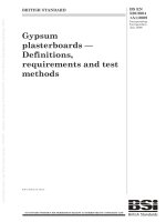
Key
1 Wall thickness (B) 7 Guide-wall
2 Horizontal length of reinforcement cage 8 Cut off level
3 Cage width 9 Vertical length of reinforcement cage
4 Length of panel 10 Reinforcement cage
5 !Working platform level" 11 Depth of excavation (D)
6 Casting level 12 Concave portion of curved joints
Figure 1 — Geometry of a panel
6
BS EN 1538:2010+A1:2015
EN 1538:2010+A1:2015 (E)
EN 1538:2010+A1:2015 (E)
!
"
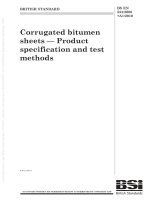
Key
P Primary
S Secondary
1 Starter
2 Intermediate
3 Closure
Figure 2 — Schematic examples of different types of panels and joints (plan view)
2 Normative references
The following referenced documents are indispensable for the application of this document. For dated
references, only the edition cited applies. For undated references, the latest edition of the referenced
document (including any amendments) applies.
!deleted text"
!EN 206:2013, Concrete ― Specification, performance, production and conformity"
EN 791, Drill rigs ― Safety
!deleted text"
EN 1990, Eurocode ― Basis of structural design
EN 1991 (all parts), Eurocode 1: Actions on structures
EN 1992 (all parts), Eurocode 2: Design of concrete structures
EN 1997-1, Eurocode 7: Geotechnical design ― Part 1: General rules
EN 1997-2, Eurocode 7 ― Geotechnical design ― Part 2: Ground investigation and testing
EN 1998 (all parts), Eurocode 8: Design of structures for earthquake resistance
7
BS EN 1538:2010+A1:2015
EN 1538:2010+A1:2015 (E)
EN 1538:2010+A1:2015 (E)
EN 10025-2, Hot rolled products of structural steels ― Part 2: Technical delivery conditions for non-alloy
structural steels
EN 10080, Steel for the reinforcement of concrete ― Weldable reinforcing steel ― General
EN 10210 (all parts), Hot finished structural hollow sections of non-alloy and fine grain steels
EN 10219 (all parts), Cold formed welded structural hollow sections of non-alloy and fine grain steels
EN 10248 (all parts), Hot rolled sheet piling of non alloy steels
EN 10249 (all parts), Cold formed sheet piling of non alloy steels
!deleted text"
EN 13670, Execution of concrete structures
3 Terms and definitions
For the purposes of this document, the following terms and definitions apply.
3.1
cast in situ concrete diaphragm wall
fr paroi moulée en béton
de Ortbetonschlitzwand
wall made of plain or reinforced concrete, which is constructed in a trench excavated in the ground
NOTE The excavation is carried out in discrete length to form panels and the concrete is placed through tremie pipes
immersed in the fresh concrete. In some cases the excavation and the concreting may be carried out in dry conditions.
3.2
plastic concrete wall
fr paroi moulée en béton plastique
de Tonbetonschlitzwand
wall made of plastic concrete, which is constructed in a trench in the ground
NOTE The excavation is carried out in panels and the concrete is placed through tremie pipes most of the time
immersed in a support fluid. In some cases the excavation and the concreting may be carried out in dry conditions.
3.3
precast concrete diaphragm wall
fr paroi préfabriquée en béton
de Fertigteilschlitzwand
wall made of precast elements which are lowered into a trench excavated in the ground containing a
hardening slurry
3.4
reinforced slurry wall
fr paroi moulée en coulis armé
de bewehrte Einphasenschlitzwand
wall made from a hardening slurry reinforced by steel beams, steel mesh or other suitable elements
3.5
slurry wall
fr paroi moulée en coulis
de Einphasenschlitzwand
wall made from a hardening slurry
NOTE In most cases, the excavation is carried out using a hardening slurry as the support fluid. Sealing elements
such as membranes or sheetpiles may be inserted.
8
BS EN 1538:2010+A1:2015
EN 1538:2010+A1:2015 (E)
EN 1538:2010+A1:2015 (E)
3.6
plastic concrete
fr béton plastique
de Tonbeton
low strength, low Young's modulus concrete capable of sustaining larger strains than normal concrete
NOTE It usually consists of low cement content concrete mixed at a high water cement ratio. It may include bentonite
and/or other clay materials and/or other materials such as pulverized fuel ash (PFA) and admixtures.
3.7
hardening slurry
fr coulis autodurcissant
de selbsterhärtende Suspension
slurry which hardens with time
NOTE The slurry is a suspension which contains cement or another binder, and additional materials such as clay
(bentonite), ground granulated blast furnace slag (GGBFS) or pulverized fuel ash (PFA), fillers, sand and admixtures.
Hardening slurries are generally used in the precast concrete diaphragm wall technique and for slurry walls. They serve as
support fluid during excavation, and, together with the fines from the natural ground, form the final, hardened material.
3.8
guide-walls
fr murettes-guides
de Leitwände
shallow depth, parallel temporary walls which are used to provide a guide for the excavating tool, to secure the
sides of the trench against collapse at the trench top close to platform level, and to support and to facilitate the
positioning of the reinforcement
3.9
panel
fr panneau
de Schlitzwandelement !/ Schlitzwandlamelle"
section of a diaphragm wall which is concreted as a single unit
NOTE A diaphragm panel may be linear, T-shaped, L-shaped, or of other configuration.
3.10
support fluid
fr fluide stabilisateur
de Stützflüssigkeit
fluid used during excavation to support the sides of the trench
NOTE It is usually a bentonite suspension, a polymer solution or a hardening slurry.
3.11
concreting pipe
fr colonne de bétonnage
de Betonierrohr
metal pipe comprising several joined lengths, surmounted by a hopper or chute for concreting under dry
conditions
3.12
tremie pipe
fr tube plongeur
de Kontraktorrohr
concreting pipe, with watertight joints for submerged concrete placement
9
BS EN 1538:2010+A1:2015
EN 1538:2010+A1:2015 (E)
EN 1538:2010+A1:2015 (E)
3.13
cover
fr enrobage
de Betonüberdeckung
distance between the outside of the reinforcement cage and the nearest concrete surface
NOTE The nearest concrete surface considered is the nearest excavated face as formed by the excavation tool.
3.14
execution specification
fr specifications d'exécution
de bautechnische Unterlagen
set of documents covering all drawings, technical data and requirements necessary for the execution of a
particular project
NOTE The execution specification is not one document but signifies the total sum of documents required for the
execution of the work as provided by the designer to the constructor. It includes the project specification prepared to
supplement and qualify the requirements of this European Standard, as well as referring the national provisions relevant in
the place of use.
3.15
project specification
fr spécifications de l'ouvrage
de Projektspezifikationen
project specific document describing the requirements applicable for the particular project
4 Information needed for the execution of the work
4.1 General
4.1.1 Prior to the execution of the work, all necessary information shall be provided.
4.1.2 This information should include:
any legal or statutory restrictions;
the location of main grid lines for setting out;
the conditions of structures, roads, services, etc. adjacent to the work, including any necessary surveys;
a suitable quality management system, including supervision, monitoring and testing.
4.1.3 The information regarding the site conditions shall cover, where relevant:
the geometry of the site (boundary conditions, topography, access, slopes, headroom restrictions, etc.);
the existing underground structures, services, known contaminations, and archeological constraints;
the environmental restrictions, including noise, vibration, pollution;
the future or ongoing activities such as dewatering, tunnelling, deep excavations.
4.2 Special features
4.2.1 The special features shall cover, where relevant:
execution specifications (see 3.14);
previous use of the site;
10
BS EN 1538:2010+A1:2015
EN 1538:2010+A1:2015 (E)
EN 1538:2010+A1:2015 (E)
adjacent foundations (types, loads and geometry);
geotechnical information and data as specified in Clause 5;
presence of obstructions in the ground (old masonry, anchors, etc.);
presence of headroom restrictions;
presence of archeological remains;
presence of natural and/or man made cavities (mines, etc.);
!presence of contaminated ground;"
any specific requirements for the diaphragm wall, in particular those pertaining to tolerances, quality of
materials, watertightness, and type of joints;
where available, previous experience with diaphragm walls or underground works on or adjacent to the
site;
for slurry walls, permeability, strength and deformation properties of the wall material;
proposed adjacent enabling or advance works such as underpinning, pre-treatment of soil, dewatering;
diaphragm wall function (i.e. end bearing, retaining wall, cut off wall, environmental barrier, etc.).
4.2.2 Necessity, extent, procedure and content for any survey of the conditions of structures, roads,
services, etc. adjacent to the works area shall be established.
4.2.3 The survey shall be carried out and be available prior to the commencement of the works and its
conclusions shall be used to define the threshold values for any movement which may affect adjacent
structures by the works area constructions.
4.2.4 Any additional or deviating requirements falling within the permissions given in this European
Standard shall be established and agreed before the commencement of the works and the quality control
system shall be suitably amended.
NOTE Such additional or deviating requirements can be:
— reduced or increased geometrical construction deviations;
— application of different or varying construction materials;
— precast concrete elements;
— special anchorage or doweling of diaphragm walls to underlying rock;
— special reinforcement as the use of steel tubes or sections or of steel fibres;
— grouting of diaphragm walls shafts or bases;
— trimming of diaphragm walls heads by mechanical equipment.
5 Geotechnical investigation
5.1 General
5.1.1 The geotechnical investigation shall fulfil the requirements of EN 1997 (all parts).
11
BS EN 1538:2010+A1:2015
EN 1538:2010+A1:2015 (E)
EN 1538:2010+A1:2015 (E)
NOTE 1 The depth and the extent of the geotechnical investigation should be sufficient to identify all ground formations
and layers affecting the construction, to determine the relevant properties of the ground and to recognize the ground
conditions (e.g. where end bearing is to be relied on, it should demonstrate that any competent founding stratum is not
immediately underlain by a weaker stratum where there is a possibility of a punching failure or excessive movements).
NOTE 2 Relevant experience of the execution of comparable foundation works under similar conditions and/or in the
vicinity of the site has to be taken into account when determining the extent of site investigation (reference to relevant
experience is permitted if appropriate means of verification are taken e.g. by penetration, pressuremeter or other tests).
NOTE 3 Guidance is given in EN 1997-2 on the depth and the contents of investigations.
5.1.2 The geotechnical investigation report shall be available in time, to allow for reliable design and
execution of the diaphragm walls (e.g. the choice of method of execution).
5.1.3 The geotechnical investigation shall be checked to see whether if it is sufficient for the design and
execution of the diaphragm walls.
5.1.4 If the geotechnical investigations are not sufficient, a supplementary investigation shall be conducted.
5.2 Specific requirements
5.2.1 Particular attention shall be paid to the following aspects, which are relevant to the execution of
diaphragm walls:
the ground level at any point of investigation or testing relative to the recognised national datum or to a
fixed reference chart datum;
piezometric levels of all water-tables and permeability of the soils;
presence of coarse, highly permeable soils or cavities (natural or artificial), which can cause sudden
losses of support fluid and instability of the trench, and thus can require special measures;
presence, strength and deformation characteristics of soft soils, such as very soft clay or peat, which can
cause difficulties during excavation or concreting (deformation or instability);
presence of boulders or obstructions which can cause difficulties during excavation and, an assessment
of their size and frequency, when applicable;
presence, position, strength of hard rock or other hard materials which can cause difficulties during
excavation and may require the use of special tools;
detrimental chemistry of groundwater, soil and rock, and water temperatures if required;
detrimental chemistry of waste materials;
presence of pretreated soil, which can have an adverse effect during excavation;
mining beneath the site;
site stability problems (slope stability for instance).
5.2.2 The piezometric levels of the various water-tables existing on the site shall be monitored separately
and over a sufficient period of time to estimate the highest piezometric levels which can occur during
construction of the diaphragm wall.
5.2.3 Particular attention shall be paid to artesian conditions.
5.2.4 The strength of the soils and rocks shall be determined by laboratory tests and/or in situ tests over the
full depth of the diaphragm wall and to a certain depth below the base depending on the nature of the ground
and the function of the wall.
12
BS EN 1538:2010+A1:2015
EN 1538:2010+A1:2015 (E)
EN 1538:2010+A1:2015 (E)
5.2.5 When diaphragm walls are required to reach or penetrate into rock, the level of the rock surface shall
be determined in both the longitudinal and transverse directions along the length of the diaphragm wall.
5.2.6 When diaphragm walls are required to reach or penetrate into rock, the properties of the rock,
including the degree of weathering and the extent and direction of fissuring, shall be determined.
6 Materials and products
6.1 Constituents
6.1.1 General
6.1.1.1 The constituents shall meet the requirements set in the respective European Standards, the
provisions valid in the place of use and the provisions given in the project specification.
6.1.1.2 The sources of supply of constituents shall be documented and shall not be changed without prior
notification.
6.1.2 Bentonite
6.1.2.1 A distinction should be made between calcium bentonite, natural sodium bentonite and activated
bentonite, which is a sodium bentonite produced from natural calcium bentonite by ion exchange.
NOTE 1 Bentonite is a clay containing mainly the mineral montmorillonite.
NOTE 2 Bentonite is used in support fluids, either as a pure bentonite suspension or as an addition to polymer
solutions. It is also used as a constituent part of hardening slurries and of plastic concrete.
6.1.2.2 Bentonite used in bentonite suspensions shall not contain harmful constituents in such quantities
as can be detrimental to reinforcement or concrete.
6.1.2.3 The chemical and mineralogical composition of the bentonite shall be supplied.
6.1.3 Polymers
Polymers can be used as sole constituent in supporting fluids or as additives to enhance rheological
effectiveness.
NOTE 1 Polymers are materials formed of molecules from chained monomeric units.
NOTE 2 There are different types of polymers ranging from natural gums to specially tailored blends of synthetic
products.
6.1.4 Cement
!
6.1.4.1 Cements for diaphragm walls are listed in EN 206:2013, Annex D.
6.1.4.2 The use of CEM II or CEM III cement or the partial replacement of CEM I cement by type II
additions is recommended because they have been shown to have beneficial effects on concrete, such as:
improved workability;
reduced heat generation during setting;
improved durability; and
13
BS EN 1538:2010+A1:2015
EN 1538:2010+A1:2015 (E)
EN 1538:2010+A1:2015 (E)
reduced bleeding rate.
NOTE 1 The use of CEM III cement type or the replacement of CEM I cement type by ground granulated blast furnace
slag can result in reduced permeability.
NOTE 2 Bleeding is less likely to be significant with cements with fineness of grind (Blaine) of 3 800 cm2/g
or more."
!
6.1.5 Aggregates
Aggregates shall comply with EN 206:2013, Annex D.
6.1.6 Water
Mixing water shall comply with EN 206:2013.
6.1.7 Additions
The use of additions shall comply with EN 206:2013.
6.1.8 Admixtures
Admixtures shall comply with EN 206:2013."
6.2 Support fluids
6.2.1 Bentonite suspensions
6.2.1.1 A bentonite suspension shall be prepared with either natural or activated sodium bentonite.
6.2.1.2 In certain cases, e.g. when the density of the suspension has to be increased, suitable inert
materials may be added.
6.2.1.3 Other than in exceptional circumstances, (see notes) the fresh bentonite suspension shall meet
the conditions shown in Table 1 and the "re-use" or "before-concreting" bentonite suspension shall meet the
conditions shown in Table 2.
NOTE 1 Special circumstances are for example:
— soils or rock with high permeability or cavities where loss of bentonite can occur;
— high piezometric ground water levels (confined or artesian conditions);
— very loose sand or soft soils (typically with qc < 300 kPa or Cu < 15 kPa);
— salt water conditions.
NOTE 2 A bentonite suspension with sufficient shear strength can be required, e.g. in order to reduce penetration into
the ground.
6.2.1.4 At the stage "before concreting", an upper limit value between 4 % and 6 % for sand content may
be used in special cases (e.g. unreinforced walls).
14
BS EN 1538:2010+A1:2015
EN 1538:2010+A1:2015 (E)
EN 1538:2010+A1:2015 (E)
Table 1 — Characteristics for fresh bentonite suspensions
Propertya Values
Density in g/cm3 < 1,10
Marsh valueb in s 32 to 50
Fluid lossc in cm3 < 30
pH 7 to 11
Filter cake in mm < 3
a See Table 2 , Footnotes a to c for the test
procedures.
b The Marsh value is the time required for
a volume of 946 ml to flow through the orifice
of the cone. A volume of 1 000 ml may be
used, but in this case, the Marsh value should
be adjusted.
c The duration of the fluid loss test may be
reduced to 7,5 min for routine control tests.
However, in this case, the values for fluid loss
and filter cake shall be adjusted. The fluid loss
for the 7,5 min test will be approximately half
of the value obtained in the 30 min test.
Table 2 — Characteristics for bentonite suspensions
Propertya re-use Stages
Density in g/cm3 < 1,25 before concreting
< 1,15
Marsh valueb in s 32 to 60 32 to 50
Fluid lossc in cm3 < 50 not applicable
pHd 7 to 12 not applicable
Sand content in % volume not applicable < 4
Filter cake in mm < 6 not applicable
a The Marsh value, the fluid loss, the sand content and the filter cake can be measured, for
example, using the tests described in EN ISO 13500.
b The Marsh value is the time required for a volume of 946 ml to flow through the orifice of the
cone. A volume of 1 000 ml may be used, but in this case, the Marsh value should be adjusted.
c The duration of the fluid loss test may be reduced to 7,5 min for routine control tests. However, in
this case, the values for fluid loss and filter cake shall be adjusted. The fluid loss for the 7,5 min test
will be approximately half of the value obtained in the 30 min test.
d Indicative values.
6.2.2 Polymer solutions
6.2.2.1 Polymers may be designed to work in conjunction with bentonite or used as stand alone support
fluids.
6.2.2.2 Polymer use shall be based on full-scale trial trenches on the site or on the basis of comparable
experience in similar geotechnical conditions.
15
BS EN 1538:2010+A1:2015
EN 1538:2010+A1:2015 (E)
EN 1538:2010+A1:2015 (E)
NOTE EN 1997-1 defines comparable experience as an experience which relates to similar works in similar
conditions and is well documented or otherwise clearly established.
6.2.2.3 Where respective European Standards are not available the suspensions shall be prepared,
maintained and controlled in accordance with respective national standards or requirements, or where these
do not apply, to the manufacturer’s instructions.
6.2.3 Fresh hardening slurries
6.2.3.1 Fresh hardening slurries as supporting fluids shall be suitable to ensure the support of the
excavated trench during excavation process.
6.2.3.2 A hardening slurry may be prepared with calcium bentonite or activated sodium bentonite as well
as cementitious binders.
6.2.3.3 Admixtures may be used to adjust the setting time of the slurry and its consistency during
excavation and during any subsequent insertion of elements.
6.2.3.4 The possible effects of temperature and chemical components of the soil and groundwater on the
setting time shall be taken into account when admixtures are selected.
6.3 Concrete
!
6.3.1 General
6.3.1.1 Concrete shall comply with EN 206:2013.
6.3.1.2 Cast in situ concrete shall be composed to minimize segregation during placing, to flow easily
around the reinforcement, and when set, to provide a dense and low permeability material.
6.3.1.3 The concrete shall comply with the requirements related to strength and durability in the hardened
state as well as with the requirements related to consistency in the fresh state.
6.3.2 Aggregates
Aggregates shall comply with EN 206:2013.
6.3.3 Cement contents
The minimum cement contents shall conform with EN 206:2013, Table D.2.
6.3.4 Water/cement ratio
The water/cement ratio shall comply with EN 206:2013.
6.3.5 Admixtures
Admixtures used shall comply with EN 206:2013.
NOTE 1 The admixtures commonly used for concreting are:
— water reducing/plasticizing;
— high range water reducing/super-plasticizing; and
— set retarding.
NOTE 2 Admixtures are used:
16
BS EN 1538:2010+A1:2015
EN 1538:2010+A1:2015 (E)
EN 1538:2010+A1:2015 (E)
— to give a mix of high plasticity;
— to improve concrete flow;
— to minimize bleeding and avoid honeycombing or segregation that might otherwise result from a high water content;
— to prolong the workability as required for the duration of the placement to cater for any interruptions in the placement
process.
NOTE 3 Inappropriate application of admixtures can result into damages.
6.3.6 Fresh concrete
Concrete shall comply with EN 206:2013, Annex D."
!deleted text"
6.3.7 Sampling and testing on site
6.3.7.1 All sampling and testing of fresh concrete on site shall comply with EN 13670 and the execution
specification.
NOTE 1 Conformity testing to confirm that the properties of the concrete comply with the specification is part of
producers obligations (see !EN 206:2013").
NOTE 2 Additional sampling can be specified in special cases at the point of delivery, just before placing, to check the
properties of the concrete (e.g. in case of high stresses or when the concrete is not produced in a certified quality
assurance system).
6.3.7.2 The minimum number of cylinder or cube specimens in a sample is three.
6.3.7.3 When the concrete is not produced in a certified quality assurance system, sampling and
compressive strength testing shall be carried out.
6.3.7.4 Where the concrete is produced in a continuous and certified quality assurance system, deviating
requirements from those of non certified quality assurance system for concrete sampling on site may be
specified.
6.3.7.5 The frequency of testing of consistence, concrete temperature and workability time shall comply
with the execution specifications.
NOTE Guidance is given in Annex B in Tables B.1 to B.5.
6.3.7.6 A full record of all tests carried out on the concrete shall be kept and results shall be noted in the
concreting record.
6.4 Plastic concrete
Plastic concrete shall be produced in accordance with the execution specification in order to obtain the
specified deformability and permeability, together with adequate workability and strength.
NOTE 1 Plastic concrete is used for cut-off walls when, in addition to low permeability, high deformability is required.
NOTE 2 Their constituent parts are:
— fine grain material (e.g. silt, clay or bentonite);
— cement or another binder;
— well-graded aggregates;
17
BS EN 1538:2010+A1:2015
EN 1538:2010+A1:2015 (E)
EN 1538:2010+A1:2015 (E)
— water;
— and possibly additions and admixtures.
NOTE 3 For plastic concrete limiting w/c ratio does not apply.
!NOTE 4 For plastic concrete it can be more suitable to specify the compressive strength not at 28 days but at a later
age more representative of the long-term performance of the structure (see EN 206:2013, 5.5.1.2(3)). Knowledge of the
long term strength and deformability can be necessary."
6.5 Hardening slurry
6.5.1 Hardening slurry shall be produced in accordance with the execution specification in order to obtain
the specified deformability and permeability, together with adequate workability and strength.
NOTE 1 Hardening slurries are used for precast concrete diaphragm walls and for cut-off walls when, in addition to low
permeability, high deformability is required.
NOTE 2 Their constituent parts are:
— fine grain material (e.g. silt, clay or bentonite);
— cement or another binder;
— water;
— and possibly additions and admixtures.
NOTE 3 These constituents can be delivered as pre-mix products.
!NOTE 4 For hardening slurry it can be more suitable to specify the compressive strength not at 28 days but at an
earlier or later age more representative for the long-term performance of the structure and the knowledge of long term
strength and deformability can be necessary."
6.5.2 The characteristics of the hardened material, as needed for the particular applications (e.g.
permeability, strength and deformation properties), together with testing methods, shall be specified to satisfy
the functional requirements of the wall.
6.6 Reinforcement
6.6.1 Reinforcement material used in diaphragm walls shall comply with the relevant European Standards
and the execution specification.
6.6.2 The reinforcement steel cages used in diaphragm walls shall comply with EN 10080.
6.6.3 The steel elements used in diaphragm walls shall comply with EN 10025-2, EN 10210 (all parts), EN
10219 (all parts), EN 10248 (all parts), EN 10249 (all parts) and EN 13670 where relevant.
NOTE Different types of steel element may be used such as cold formed or hot rolled sheet pile products or structural
hollow products, etc.
6.6.4 Materials other than steel to be used as reinforcement such as glass fibre shall have an established
suitability and be in accordance with the requirements given in the execution specification. .
6.6.5 Unless special precautions are taken, metallic elements used in cast in situ diaphragm walls, such as
access pipes for testing purpose, shall not be made of galvanized steel or other metals which can produce
electrostatic effects causing electrochemical corrosion of the reinforcement.
NOTE Electrostatic effects can also adversely affect support fluids, for example build up of a bentonite layer using
bentonite suspensions or spider web formation in polymer solutions which can inhibit successful concreting.
18