Bsi bs en 01677 3 2001 + a1 2008
Bạn đang xem bản rút gọn của tài liệu. Xem và tải ngay bản đầy đủ của tài liệu tại đây (585.63 KB, 20 trang )
BRITISH STANDARD
Components for
slings — Safety —
Part 3: Forged steel self-locking
hooks — Grade 8
ICS 53.020.30
NO COPYING WITHOUT BSI PERMISSION EXCEPT AS PERMITTED BY COPYRIGHT LAW
BS EN
1677-3:2001
+A1:2008
BS EN 1677-3:2001+A1: 2008
National foreword
This British Standard is the UK implementation of EN 1677-3:2001+A1:2008.
It supersedes BS EN 1677-3:2001.
The start and finish of text introduced or altered by amendment is indicated
in the text by tags. Tags indicating changes to CEN text carry the number of
the CEN amendment. For example, text altered by CEN amendment A1 is
indicated by
.
ab
The UK participation in its preparation was entrusted to Technical Committee
MHE/1, Chains and fittings.
A list of organizations represented on this committee can be obtained on
request to its secretary.
A British Standard does not purport to include all the necessary provisions of a
contract. Users are responsible for its correct application.
Compliance with a British Standard cannot confer immunity from
legal obligations.
This British Standard, having
been prepared under the
direction of the Engineering
Sector Policy and Strategy
Committee, was published
under the authority of the
Standards Policy and Strategy
Committee on
06 November 2001
Amendments issued since publication
© BSI 2009
ISBN 978 0 580 602696
Date
Comments
31 May 2009
Implementation of CEN amendment A1:2008
EUROPEAN STANDARD
EN 1677-3:2001+A1
NORME EUROPÉENNE
EUROPÄISCHE NORM
April 2008
ICS 53.020.30
Supersedes EN 1677-3:2001
English Version
Components for slings - Safety - Part 3: Forged steel selflocking hooks - Grade 8
Accessoires pour élingues - Sécurité - Partie 3: Crochets
autobloquants en acier forgé - Classe 8
Einzelteile für Anschlagmittel - Sicherheit - Teil 3:
Geschmiedete, selbstverriegelnde Haken - Güteklasse 8
This European Standard was approved by CEN on 11 August 2001 and includes Amendment 1 approved by CEN on 21 February 2008.
CEN members are bound to comply with the CEN/CENELEC Internal Regulations which stipulate the conditions for giving this European
Standard the status of a national standard without any alteration. Up-to-date lists and bibliographical references concerning such national
standards may be obtained on application to the CEN Management Centre or to any CEN member.
This European Standard exists in three official versions (English, French, German). A version in any other language made by translation
under the responsibility of a CEN member into its own language and notified to the CEN Management Centre has the same status as the
official versions.
CEN members are the national standards bodies of Austria, Belgium, Bulgaria, Cyprus, Czech Republic, Denmark, Estonia, Finland,
France, Germany, Greece, Hungary, Iceland, Ireland, Italy, Latvia, Lithuania, Luxembourg, Malta, Netherlands, Norway, Poland, Portugal,
Romania, Slovakia, Slovenia, Spain, Sweden, Switzerland and United Kingdom.
EUROPEAN COMMITTEE FOR STANDARDIZATION
COMITÉ EUROPÉEN DE NORMALISATION
EUROPÄISCHES KOMITEE FÜR NORMUNG
Management Centre: rue de Stassart, 36
© 2008 CEN
All rights of exploitation in any form and by any means reserved
worldwide for CEN national Members.
B-1050 Brussels
Ref. No. EN 1677-3:2001+A1:2008: E
BS EN 1677-3:2001+A1:2008
EN 1677-3:2001+A1:2008 (E)
Contents
Page
Foreword..............................................................................................................................................................3
Introduction .........................................................................................................................................................4
1
Scope ......................................................................................................................................................4
2
Normative references ............................................................................................................................4
3
Terms and definitions ...........................................................................................................................5
4
Significant Hazards................................................................................................................................5
5
5.1
5.2
5.3
5.4
5.5
Safety requirements ..............................................................................................................................6
Design .....................................................................................................................................................6
Dimensions.............................................................................................................................................6
Materials and heat treatment ................................................................................................................8
Manufacturing methods and workmanship ........................................................................................8
Mechanical properties ...........................................................................................................................9
6
6.1
6.2
6.3
Verification of safety requirements......................................................................................................9
Qualification of personnel ....................................................................................................................9
Type tests ...............................................................................................................................................9
Manufacturing test regime and acceptance criteria.........................................................................11
7
Marking .................................................................................................................................................12
8
Manufacturer’s certificate ...................................................................................................................12
9
Information for use ..............................................................................................................................12
Annex A (informative) Bases for the calculation of hook dimensions ........................................................13
Annex B (informative) Designation system for self-locking hooks - grade 8 .............................................14
B.1
Designation ..........................................................................................................................................14
B.2
General format .....................................................................................................................................14
Annex ZA (informative) !Relationship between this European Standard and the Essential
Requirements of EU Directive 98/37/EC ............................................................................................15
Annex ZB (informative) !Relationship between this European Standard and the Essential
Requirements of EU Directive 2006/42/EC ........................................................................................16
Bibliography ......................................................................................................................................................17
2
BS EN 1677-3:2001+A1:2008
EN 1677-3:2001+A1:2008 (E)
Foreword
This document (EN 1677-3:2001+A1:2008) has been prepared by Technical Committee CEN/TC 168 “Chains,
ropes, webbing, slings and accessories - Safety”, the secretariat of which is held by BSI.
This European Standard shall be given the status of a national standard, either by publication of an identical
text or by endorsement, at the latest by October 2008, and conflicting national standards shall be withdrawn at
the latest by October 2008.
This document includes Amendment 1, approved by CEN on 2008-02-21.
This document supersedes EN 1677-3:2001.
The start and finish of text introduced or altered by amendment is indicated in the text by tags ! ".
This document has been prepared under a mandate given to CEN by the European Commission and the
European Free Trade Association, and supports essential requirements of EC Directive(s).
For the relationship with EC Directives, see informative Annexes ZA and ZB, which are integral parts of this
document.
This European Standard is a part of a products standard related to safety for components for slings.
The other Parts of EN 1677 for components for slings are:
Part 1: Forged steel components - Grade 8
Part 2: Forged steel lifting hooks with latch - Grade 8
Part 4: Links - Grade 8
Part 5: Forged steel lifting hooks with latch - Grade 4
Part 6: Links - Grade 4
Annexes A and B of this European Standard are informative.
According to the CEN/CENELEC Internal Regulations, the national standards organizations of the following
countries are bound to implement this European Standard: Austria, Belgium, Bulgaria, Cyprus, Czech
Republic, Denmark, Estonia, Finland, France, Germany, Greece, Hungary, Iceland, Ireland, Italy, Latvia,
Lithuania, Luxembourg, Malta, Netherlands, Norway, Poland, Portugal, Romania, Slovakia, Slovenia, Spain,
Sweden, Switzerland and United Kingdom.
3
BS EN 1677-3:2001+A1:2008
EN 1677-3:2001+A1:2008 (E)
Introduction
This European Standard has been prepared to be a harmonized standard providing one means of complying
with the essential safety requirements of the Machinery Directive and associated EFTA regulations.
The hooks covered by this Part of EN 1677 are normally supplied to be part of a sling, but they may also be
used for other applications. In such instances it is important that the hook design is checked to ensure its
fitness for the intended use.
The extent to which hazards are covered is indicated in the scope. In addition, lifting equipment shall conform
as appropriate to EN 292 for hazards that are not covered by this standard.
1
Scope
This European Standard specifies requirements for forged steel self-locking lifting hooks of Grade 8 having
eye or clevis and pin up to 21,2 t working load limit (WLL), mainly for use in:
chain slings according to EN 818-4
steel wire rope slings according to prEN 13414-1
textile slings according to EN 1492-1, EN 1492-2
intended for lifting objects, materials or goods.
The hazards covered by this part of EN 1677 are identified in clause 4.
Annex A gives the bases for calculation of hook dimensions.
Annex B gives an example of a designation systems for hooks of Grade 8.
2
Normative references
This European Standard incorporates by dated or undated reference provisions from other publications.
These normative references are cited at the appropriate places in the text and the publications are listed
hereafter. For dated references, subsequent amendments to or revisions of any of these publications apply to
this European Standard only when incorporated in it by amendment or revision. For undated references the
latest edition of the publication referred to applies (including amendments).
EN 292-2:1991/A1:1995, Safety of machinery - Basic concepts, general principles for design - Part 2:
Technical principles and specifications (Amendment 1:1995)
EN 818-4, Short link chain for lifting purposes - Safety - Part 4: Chain slings - Grade 8
EN 818-6, Short link chain for lifting purposes - Safety - Part 6: Chain slings - Specification for information for
use and maintenance to be provided by the manufacturer
EN 1050:1996, Safety of machinery - Principles for risk assessment
EN 1492-1, Textile slings - Safety - Part 1: Flat woven webbing slings, made of man-made fibres, for general
purpose use
4
BS EN 1677-3:2001+A1:2008
EN 1677-3:2001+A1:2008 (E)
EN 1492-2, Textile slings - Safety - Part 2: Roundslings, made of man-made fibres, for general purpose use
!EN 1677-1:2000+A1:2008", Components for slings - Safety - Part 1: Forged steel components, Grade 8
prEN 13414-1, Steel wire rope slings - Safety - Part 1: Wire rope slings
3
Terms and definitions
For the purposes of this European Standard, the terms and definitions given in !EN 1677-1+A1:2008"
apply, together with the following.
3.1
self-locking hook
hook containing a locking mechanism, capable of being activated by the action of the load which, once
correctly closed and locked, can only be opened in the unloaded condition by de-activation of the locking
mechanism
4
Significant Hazards
Accidental release of a load or release of a load due to failure of a hook puts at risk, either directly or
indirectly, the safety or health of those persons within the danger zone.
In order to provide the necessary strength and durability of hooks this Part of EN 1677 gives requirements for
the design, manufacture and testing to ensure the specified levels of performance are met.
Since failure can be caused by the incorrect choice of grade and specification of hook, this Part of EN 1677
also gives requirements for marking and the manufacturer's certificate.
Errors of fitting can also lead to failure and this Part of EN 1677 contains dimensional requirements to allow
correct fit.
Risk of injury due to sharp edges, sharp angles or rough surfaces when handling is also covered by this
standard.
Those aspects of safe use associated with good practice are given in EN 818-6.
Table 1 contains those hazards which require action to reduce risk identified by risk assessment as being
specific and significant for forged steel self-locking hooks of grade 8.
Table 1 — Significant hazards and associated requirements
Hazards identified in accordance
with annex A of EN 1050:1996
1.e
Mechanical hazard
due to inadequacy of
strength
1.3
1.8
15
Cutting hazard
Friction or abrasion
Errors of fitting hazard
Relevant clause of
annex A of EN 292-2:
1991/A1:1995
Relevant clause /
subclause of this Part of
EN 1677
1.3.2
4.1.2.3
4.1.2.5
4.2.4
1.7.3
1.3.4
1.3.4
1.5.4
5
5
5
5
7
5.4
5.4
5.2
5
BS EN 1677-3:2001+A1:2008
EN 1677-3:2001+A1:2008 (E)
5
5.1
Safety requirements
Design
The articulation and relative movement shall be in accordance with 5.1 of !EN 1677-1:2000+A1:2008".
NOTE 1
The form of the hook is not specified in detail. For example, a minimum value of dimension F (see Figure 1) as
measured in any direction is specified so that the eye of the hook can accommodate a pin, but the eye of the hook need
not be circular.
The form of the upper end shall be either of the eye type or the clevis type as designated in Table 2.
A closed hook in the finished condition shall be able to withstand a bend test in accordance with 6.2.2 (see
Figure 2).
The latch shall be able to withstand a force f1, of 3000 N or equivalent to 20 % of the working load limit of the
hook, whichever is the greater, when applied equidistant between the point of the hook and the centre of
rotation of the latch (see Figure 3).
The latch, when the hook is correctly closed and locked, shall be able to withstand a force f2, applied laterally
to f1, as close as practicable to the tip of the latch, of 3000 N or equivalent to 10 % of the working load limit,
whichever is the greater.
The locking mechanism shall be activated by the application of the load and shall be replaceable.
The hook shall be able to withstand an impact to the eye or clevis of the latch, without opening, when tested in
accordance with 6.2.4. The forces transmitted between the lock and the latch shall not be such that an impact
on the latch causes a moment in the direction of rotation that opens the lock.
The surface hardness of the lock shall be greater than that of the latch.
NOTE 2
The hook should be easy to handle and operate.
NOTE 3
The locking mechanism should be protected against ingress and entrapment of dust or other solids.
5.2
Dimensions
The principal dimensions of the hook shall conform to Table 3, in which the hook dimensions are related to the
working load limit.
NOTE 1
With an eye type hook, connecting devices can be required.
NOTE 2
For direct use in wire rope slings and/or textile slings, dimension F should be larger than the minimum value
given in Table 3.
In addition, the following requirements shall be met:
a) the actual throat opening O is the smaller of O1 and O2
b) the actual point height B shall be at least 65 % of the actual throat opening O (see Figure 1);
c) the actual throat opening O (see Figure 1) shall not exceed 95 % of the actual seat diameter D;
d) in the case of hooks having a clevis, the dimensions of the load pin and the slot on the clevis shall ensure
articulation between pin and the chain;
e) the hook shall be able to close over the maximum diameter of bar A, as indicated in Figure 1, that can be
admitted through the actual throat opening O;
6
BS EN 1677-3:2001+A1:2008
EN 1677-3:2001+A1:2008 (E)
f)
the maximum values for H and L given in Table 3 shall not apply in the region of the locking mechanism.
Table 2 — Forms of hooks
Form
Description
Principal use
E
Eye type
Chain slings, wire
rope slings and textile
slings
C
Clevis type
Mechanically
assembled chain
slings
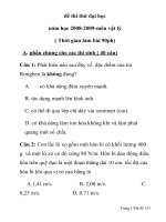
Key
1
2
3
4
5
6
Eye type
Clevis type
Load bearing pivot pin
Example of locking mechanism
Latch
Maximum diameter of bar
Figure 1 — Dimensions of self-locking hooks
7
BS EN 1677-3:2001+A1:2008
EN 1677-3:2001+A1:2008 (E)
Table 3 — Dimensions of hooks (see Figure 1)
Code
Working
D
O
F
H
L
Number
load limit
min.
min.
min.
max
max.
(WLL)
mm
mm
mm
mm
mm
t
5.3
6
7
8
1,12
1,5
2
22
26
30
17
20
23
12
14
16
25
29
34
17
20
23
9
10
11
2,5
3,15
4
34
38
42
26
29
32
18
20
23
38
43
48
26
29
32
13
14
16
5,3
6
8
49
52
60
37
40
46
26
28
32
55
59
68
37
40
46
18
19
20
10
11,2
12,5
67
71
75
51
54
57
36
38
40
76
80
85
51
54
57
22
23
25
15
16
20
82
85
95
63
65
72
44
46
51
93
96
107
63
65
72
26
21,2
98
75
52
111
75
Materials and heat treatment
The materials and heat treatment of all load bearing parts of self-locking hooks, including pins, shall be in
accordance with 5.2 of !EN 1677-1:2000+A1:2008".
5.4
5.4.1
Manufacturing methods and workmanship
General
Manufacturing methods and workmanship shall be in accordance with 5.3 of !EN 1677-1:2000+A1:2008".
5.4.2
Hook tip clearance
For hooks in the finished condition, clearance between the tip of the hook and the latch in the closed condition
shall not be greater than indicated in Table 4.
8
BS EN 1677-3:2001+A1:2008
EN 1677-3:2001+A1:2008 (E)
Table 4 — Clearance between hook tip and latch
5.5
Code numbers
Maximum
clearance mm
6 to 10
1
11 to 14
1,5
16 to 18
2
19 to 26
3
Mechanical properties
The mechanical properties of all load bearing parts of self-locking hooks, including pins, shall be in
accordance with 5.4 of !EN 1677-1:2000+A1:2008".
6
Verification of safety requirements
6.1
Qualification of personnel
All testing and examination shall be carried out by a competent person.
6.2
Type tests
6.2.1
General
Type tests and acceptance criteria shall be in accordance with 6.2 of !EN 1677-1:2000+A1:2008".
In the tests specified in 6.2.3 to 6.2.5 of !EN 1677-1:2000+A1:2008", the force shall be applied to the
hook axially without shock, using a test fixture of diameter not greater than 60 % of the seat diameter, D, of
the hook.
The static tensile test shall be carried out with the hook in the correctly locked position.
6.2.2
6.2.2.1
Bend test
General
A closed hook in the finished condition shall be bend tested in a 120°-V-die (see Figure 2) by application of a
force (f), to verify the lateral ductility of the structure and the load-bearing pivot pin. If the hook is not
symmetrical due to the locking mechanism or the method of securing the pivot pin, both sides shall be tested,
using different hooks for each test side.
9
BS EN 1677-3:2001+A1:2008
EN 1677-3:2001+A1:2008 (E)
Key
1 mandrel
r =1,5 x code number (in mm)
Figure 2 — Bend test device
6.2.2.2
Acceptance criteria for the bend test
After application and removal of a force (f) equivalent to 40 % of the working load limit, it shall be possible to
freely open the hook by hand.
After application and removal of a force (f) equivalent to the working load limit there shall be no visible sign of
cracking or fracture.
6.2.3
Testing the latch
A type test to verify conformity to 5.1 shall be carried out with the latch fitted or in a test device allowing
application of the forces f1 and f2 (see 5.1 and Figure 3).
The latch shall show no signs of permanent deformation.
10
BS EN 1677-3:2001+A1:2008
EN 1677-3:2001+A1:2008 (E)
Figure 3 — Points of application of forces to the latch
6.2.4
Impact testing of lock
The hook shall be supported so that it is held in a fixed position with the eye or clevis of the latch at the bottom
of a pendulum. The eye or clevis shall be impacted by a mass attached to the end of the pendulum such that
the impact occurs in the direction of opening of the latch. The test shall be carried out in accordance with
either method a) or method b) as follows:
a)
The pendulum shall be released from an angle of 60° to the vertical and the mass attached to the
pendulum shall be greater than or equal to the mass of the hook. The effective pendulum length shall be
1 m.
b)
A suitable combination of test mass, pendulum length and release angle, having an equivalent impact
energy greater than or equal to method a) shall be used. The corresponding impact velocity shall be at
least 1,5 m/s.
Prior to a series of tests on any hook, grease shall be applied to the surface of the lock where it bears onto the
latch. Prior to each test the latch shall be opened and closed manually.
Five tests shall be carried out on each of three hooks of either eye or clevis type, at each size in the range. No
hook shall open in any test. Tests shall be repeated for any variation in latch or locking device design, or
method of manufacture.
6.3
6.3.1
Manufacturing test regime and acceptance criteria
General
Manufacturing test regime and
!EN 1677-1:2000+A1:2008".
6.3.2
acceptance
criteria
shall
be
in
accordance
with
6.5
of
Measurement of hook tip clearance
The hook tip clearance of each hook shall be checked and shall conform to 5.4.2.
11
BS EN 1677-3:2001+A1:2008
EN 1677-3:2001+A1:2008 (E)
7
Marking
Marking shall be in accordance with clause 7 of !EN 1677-1:2000+A1:2008".
8
Manufacturer’s certificate
The manufacturer's certificate shall conform to clause 8 of !EN 1677-1:2000+A1:2008".
9
Information for use
Information for use shall accompany the hook(s) and shall conform to the relevant clauses of EN 818-6.
Advice shall be given on how to assemble and disassemble forged steel self-locking clevis hooks and how to
ensure the correct fit of the pin.
Instructions shall be given on how to:
a)
Close the latch manually by the operator;
b)
How to use the locking mechanism.
12
BS EN 1677-3:2001+A1:2008
EN 1677-3:2001+A1:2008 (E)
Annex A
(informative)
Bases for the calculation of hook dimensions
The dimensions given in Table 3 are derived from the following equations:
D = 21,2
WLL
O = 16,2
WLL
F = 11,4
WLL
H = 24
WLL
L = 16,2
WLL
The dimensions (in millimetres) have been calculated using the WLL given in Table 3 and rounded to the nearest
whole number.
13
BS EN 1677-3:2001+A1:2008
EN 1677-3:2001+A1:2008 (E)
Annex B
(informative)
Designation system for self-locking hooks - grade 8
B.1 Designation
Designation of hooks should be in accordance with the general format given in B.2. The denomination of a selflocking hook should be determined by the manufacturer.
B.2 General format
--
Denomination
EN Number block
Grade number
Form letter
(see Table 2)
Code number
(see Table 3)
14
- EN 1677-3 -
8
-
E
-
18
BS EN 1677-3:2001+A1:2008
EN 1677-3:2001+A1:2008 (E)
Annex ZA
(informative)
!Relationship between this European Standard and the Essential
Requirements of EU Directive 98/37/EC
This European Standard has been prepared under a mandate given to CEN by the European Commission
and the European Free Trade Association to provide a means of conforming to Essential Requirements of the
New Approach Directive 98/37/EC, amended by 98/79/CE on machinery.
Once this standard is cited in the Official Journal of the European Communities under that Directive and has
been implemented as a national standard in at least one Member State, compliance with the normative
clauses of this standard confers, within the limits of the scope of this standard, a presumption of conformity
with the relevant Essential Requirements of that Directive and associated EFTA regulations.
WARNING - Other requirements and other EU Directives may be applicable to the product(s) falling within the
scope of this standard."
15
BS EN 1677-3:2001+A1:2008
EN 1677-3:2001+A1:2008 (E)
Annex ZB
(informative)
!Relationship between this European Standard and the Essential
Requirements of EU Directive 2006/42/EC
This European Standard has been prepared under a mandate given to CEN by the European Commission
and the European Free Trade Association to provide a means of conforming to Essential Requirements of the
New Approach Directive 2006/42/EC on machinery.
Once this standard is cited in the Official Journal of the European Communities under that Directive and has
been implemented as a national standard in at least one Member State, compliance with the normative
clauses of this standard confers, within the limits of the scope of this standard, a presumption of conformity
with the relevant Essential Requirements of that Directive and associated EFTA regulations.
WARNING - Other requirements and other EU Directives may be applicable to the product(s) falling within the
scope of this standard."
16
BS EN 1677-3:2001+A1:2008
EN 1677-3:2001+A1:2008 (E)
Bibliography
EN 292-1:1991, Safety of machinery - Basic concepts, general principles for design - Part 1: Basic
terminology, methodology
17
BS EN
1677-3:2001
+A1:2008
British Standards Institution (BSI)
BSI is the independent national body responsible for preparing
British Standards. It presents the UK view on standards in Europe and at the
international level. It is incorporated by Royal Charter.
Revisions
British Standards are updated by amendment or revision. Users of
British Standards should make sure that they possess the latest amendments or
editions.
It is the constant aim of BSI to improve the quality of our products and services.
We would be grateful if anyone finding an inaccuracy or ambiguity while using
this British Standard would inform the Secretary of the technical committee
responsible, the identity of which can be found on the inside front cover.
Tel: +44 (0)20 8996 9000 Fax: +44 (0)20 8996 7400
BSI offers members an individual updating service called PLUS which ensures
that subscribers automatically receive the latest editions of standards.
Buying standards
Orders for all BSI, international and foreign standards publications should be
addressed to Customer Services.
Tel: +44 (0)20 8996 9001 Fax: +44 (0)20 8996 7001
Email:
You may also buy directly using a debit/credit card from the BSI Shop on the
Website />In response to orders for international standards, it is BSI policy to supply the
BSI implementation of those that have been published as British Standards,
unless otherwise requested.
Information on standards
BSI provides a wide range of information on national, European and
international standards through its Library and its Technical Help to Exporters
Service. Various BSI electronic information services are also available which give
details on all its products and services. Contact the Information Centre.
Tel: +44 (0)20 8996 7111 Fax: +44 (0)20 8996 7048
Email:
Subscribing members of BSI are kept up to date with standards developments
and receive substantial discounts on the purchase price of standards. For details
of these and other benefits contact Membership Administration.
Tel: +44 (0)20 8996 7002 Fax: +44 (0)20 8996 7001
Email:
Information regarding online access to British Standards via British Standards
Online can be found at />Further information about BSI is available on the BSI website at
.
Copyright
BSI Group Headquarters
389 Chiswick High Road,
London W4 4AL, UK
Tel +44 (0)20 8996 9001
Fax +44 (0)20 8996 7001
www.bsigroup.com/standards
Copyright subsists in all BSI publications. BSI also holds the copyright, in the
UK, of the publications of the international standardization bodies. Except as
permitted under the Copyright, Designs and Patents Act 1988 no extract may be
reproduced, stored in a retrieval system or transmitted in any form or by any
means – electronic, photocopying, recording or otherwise – without prior written
permission from BSI.
This does not preclude the free use, in the course of implementing the standard,
of necessary details such as symbols, and size, type or grade designations. If these
details are to be used for any other purpose than implementation then the prior
written permission of BSI must be obtained.
Details and advice can be obtained from the Copyright & Licensing Manager.
Tel: +44 (0)20 8996 7070 Email: