Bsi bs en 01870 11 2013
Bạn đang xem bản rút gọn của tài liệu. Xem và tải ngay bản đầy đủ của tài liệu tại đây (1.08 MB, 48 trang )
BS EN 1870-11:2013
BSI Standards Publication
Safety of woodworking
machines — Circular sawing
machines
Part 11: Semi automatic horizontal cross-cut
sawing machines with one saw unit (radial
arm saws)
BS EN 1870-11:2013
BRITISH STANDARD
National foreword
This British Standard is the UK implementation of EN 1870-11:2013.
It supersedes BS EN 1870-11:2003+A1:2009 which is withdrawn.
The UK participation in its preparation was entrusted to Technical
Committee MTE/23, Woodworking machines.
A list of organizations represented on this committee can be
obtained on request to its secretary.
This publication does not purport to include all the necessary
provisions of a contract. Users are responsible for its correct
application.
© The British Standards Institution 2013.
Published by BSI Standards Limited 2013
ISBN 978 0 580 73573 8
ICS 79.120.10
Compliance with a British Standard cannot confer immunity from
legal obligations.
This British Standard was published under the authority of the
Standards Policy and Strategy Committee on 31 October 2013.
Amendments/corrigenda issued since publication
Date
Text affected
BS EN 1870-11:2013
EN 1870-11
EUROPEAN STANDARD
NORME EUROPÉENNE
EUROPÄISCHE NORM
October 2013
ICS 79.120.10
Supersedes EN 1870-11:2003+A1:2009
English Version
Safety of woodworking machines - Circular sawing machines Part 11: Semi automatic horizontal cross-cut sawing machines
with one saw unit (radial arm saws)
Sécurité des machines pour le travail du bois - Machines
scies circulaires - Partie 11: Tronỗonneuses semiautomatiques coupe horizontale avec une unité de sciage
(scies circulaires radiales)
Sicherheit von Holzbearbeitungsmaschinen Kreissägemaschinen - Teil 11: Halbautomatische
waagrecht schneidende Auslegerkreissägemaschinen mit
einem Sägeaggregat (Radialsägen)
This European Standard was approved by CEN on 24 August 2013.
CEN members are bound to comply with the CEN/CENELEC Internal Regulations which stipulate the conditions for giving this European
Standard the status of a national standard without any alteration. Up-to-date lists and bibliographical references concerning such national
standards may be obtained on application to the CEN-CENELEC Management Centre or to any CEN member.
This European Standard exists in three official versions (English, French, German). A version in any other language made by translation
under the responsibility of a CEN member into its own language and notified to the CEN-CENELEC Management Centre has the same
status as the official versions.
CEN members are the national standards bodies of Austria, Belgium, Bulgaria, Croatia, Cyprus, Czech Republic, Denmark, Estonia,
Finland, Former Yugoslav Republic of Macedonia, France, Germany, Greece, Hungary, Iceland, Ireland, Italy, Latvia, Lithuania,
Luxembourg, Malta, Netherlands, Norway, Poland, Portugal, Romania, Slovakia, Slovenia, Spain, Sweden, Switzerland, Turkey and United
Kingdom.
EUROPEAN COMMITTEE FOR STANDARDIZATION
COMITÉ EUROPÉEN DE NORMALISATION
EUROPÄISCHES KOMITEE FÜR NORMUNG
CEN-CENELEC Management Centre: Avenue Marnix 17, B-1000 Brussels
© 2013 CEN
All rights of exploitation in any form and by any means reserved
worldwide for CEN national Members.
Ref. No. EN 1870-11:2013: E
BS EN 1870-11:2013
EN 1870-11:2013 (E)
Contents
Page
Foreword ..............................................................................................................................................................4
Introduction .........................................................................................................................................................6
1
Scope ......................................................................................................................................................7
2
Normative references ............................................................................................................................7
3
Terms and definitions ........................................................................................................................ 10
4
List of significant hazards ................................................................................................................. 12
5
5.1
5.2
5.2.1
5.2.2
5.2.3
5.2.4
5.2.5
5.2.6
5.2.7
5.2.8
5.3
5.3.1
5.3.2
5.3.3
5.3.4
5.3.5
5.3.6
5.3.7
5.3.8
5.4
5.4.1
5.4.2
5.4.3
5.4.4
5.4.5
5.4.6
5.4.7
5.4.8
5.4.9
5.4.10
5.4.11
5.4.12
5.4.13
Safety requirements and/or measures ............................................................................................. 14
General ................................................................................................................................................. 14
Controls ............................................................................................................................................... 14
Safety and reliability of control systems .......................................................................................... 14
Position of controls ............................................................................................................................ 15
Starting ................................................................................................................................................ 15
Normal stopping ................................................................................................................................. 16
Emergency stop .................................................................................................................................. 16
Integrated feed .................................................................................................................................... 17
Failure of the power supply ............................................................................................................... 17
Failure of the control circuits ............................................................................................................ 18
Protection against mechanical hazards ........................................................................................... 18
Stability ................................................................................................................................................ 18
Risk of break up during operation .................................................................................................... 18
Tool holder and tool design ............................................................................................................... 19
Braking ................................................................................................................................................. 20
Devices to minimise the possibility or the effect of ejection ......................................................... 21
Work-piece supports and guides ...................................................................................................... 21
Prevention of access to moving parts .............................................................................................. 22
Clamping devices ............................................................................................................................... 26
Protection against non-mechanical hazards ................................................................................... 26
Fire ....................................................................................................................................................... 26
Noise .................................................................................................................................................... 26
Emission of chips and dust ............................................................................................................... 28
Electricity ............................................................................................................................................. 28
Ergonomics and handling .................................................................................................................. 29
Pneumatic ............................................................................................................................................ 29
Hydraulic .............................................................................................................................................. 29
Electromagnetic compatibility........................................................................................................... 30
Laser .................................................................................................................................................... 30
Static electricity .................................................................................................................................. 30
Errors of Fitting ................................................................................................................................... 30
Isolation ............................................................................................................................................... 30
Maintenance ........................................................................................................................................ 31
6
6.1
6.2
6.3
Information for use ............................................................................................................................. 31
Warning devices ................................................................................................................................. 31
Marking ................................................................................................................................................ 32
Instruction handbook ......................................................................................................................... 32
Annex A (normative) Dimensional tolerances of saw spindles .................................................................. 36
2
BS EN 1870-11:2013
EN 1870-11:2013 (E)
Annex B (normative) Impact test method for guards .................................................................................... 37
B.1
General ................................................................................................................................................. 37
B.2
Test method ......................................................................................................................................... 37
B.2.1
Preliminary remarks ............................................................................................................................ 37
B.2.2
Testing equipment ............................................................................................................................... 37
B.2.3
Projectile for guards ............................................................................................................................ 37
B.2.4
Sampling............................................................................................................................................... 37
B.2.5
Test procedure ..................................................................................................................................... 37
B.3
Results .................................................................................................................................................. 38
B.4
Assessment ......................................................................................................................................... 38
B.5
Test report ............................................................................................................................................ 38
B.6
Test equipment for impact test .......................................................................................................... 38
Annex C (normative) Braking tests ................................................................................................................. 40
C.1
Conditions for all tests........................................................................................................................ 40
C.2
Tests ..................................................................................................................................................... 40
C.2.1
Run-up time .......................................................................................................................................... 40
C.2.2
Un-braked run-down time ................................................................................................................... 40
C.2.3
Braked run-down time......................................................................................................................... 40
Annex ZA (informative) Relationship between this European Standard and the Essential
Requirements of EU Directive 2006/42/EC ........................................................................................ 42
Bibliography ...................................................................................................................................................... 43
3
BS EN 1870-11:2013
EN 1870-11:2013 (E)
Foreword
This document (EN 1870-11:2013) has been prepared by Technical Committee CEN/TC 142 “Woodworking
machines - Safety”, the secretariat of which is held by UNI.
This European Standard shall be given the status of a national standard, either by publication of an identical
text or by endorsement, at the latest by April 2014, and conflicting national standards shall be withdrawn at the
latest by April 2014.
Attention is drawn to the possibility that some of the elements of this document may be the subject of patent
rights. CEN [and/or CENELEC] shall not be held responsible for identifying any or all such patent rights.
This document supersedes EN 1870-11:2003+A1:2009.
The main modifications to the previous version include:
—
the deletion of automatic machines;
—
the deletion of displaceable machines fitted with wheels;
—
introduction of PL;
—
more precise requirements for braking function and for access to the saw blade for change;
—
to require the fence to be located on both sides of the cutting line.
This document has been prepared under a mandate given to CEN by the European Commission and the
European Free Trade Association, and supports essential requirements of the Machinery Directive.
For relationship with EU Directive, see informative Annex ZA, which is an integral part of this document.
EN 1870, Safety of woodworking machines – Circular sawing machines consists of the following parts:
—
Part 1: Circular saw benches (with and without sliding table), dimension saws and building site saws;
—
Part 3: Down cutting cross-cut saws and dual purpose down cutting cross-cut saws/circular saw benches;
—
Part 4: Multiblade rip sawing machines with manual loading and/or unloading;
—
Part 5: Circular saw benches/up-cutting cross-cut sawing machines;
—
Part 6: Circular sawing machines for firewood and dual purpose circular sawing machines for
firewood/circular saw benches, with manual loading and/or unloading;
—
Part 7: Single blade log sawing machines with integrated feed table and manual loading and/or
unloading;
—
Part 8: Single blade edging circular rip sawing machines with power driven saw unit and manual loading
and/or unloading;
—
Part 9: Double blade circular sawing machines for cross-cutting with integrated feed and with manual
loading and/or unloading;
—
Part 10: Single blade automatic and semi-automatic up-cutting cross-cut sawing machines;
4
BS EN 1870-11:2013
EN 1870-11:2013 (E)
—
Part 11: Semi automatic horizontal cross-cut sawing machines with one saw unit (radial arm saws);
—
Part 12: Pendulum cross-cut sawing machines;
—
Part 13: Horizontal beam panel sawing machines;
—
Part 14: Vertical panel sawing machines;
—
Part 15: Multi-blade cross-cut sawing machines with integrated feed of the workpiece and manual loading
and/or unloading;
—
Part 16: Double mitre sawing machines for V cutting;
—
Part 17: Manual horizontal cutting cross-cut sawing machines with one saw unit (manual radial arm
saws);
—
Part 18: Dimension saws;
—
Part 19: Circular saw benches (with and without sliding table) and building site saws.
Organisations contributing to the preparation of this European Standard include European Committee of
Woodworking Machinery Manufacturers Association “EUMABOIS”.
The European Standards produced by CEN/TC 142 are particular to woodworking machines and complement
the relevant A and B Standards on the subject of general safety (see introduction of EN ISO 12100:2010 for a
description of A, B and C standards).
According to the CEN-CENELEC Internal Regulations, the national standards organisations of the following
countries are bound to implement this European Standard: Austria, Belgium, Bulgaria, Croatia, Cyprus, Czech
Republic, Denmark, Estonia, Finland, Former Yugoslav Republic of Macedonia, France, Germany, Greece,
Hungary, Iceland, Ireland, Italy, Latvia, Lithuania, Luxembourg, Malta, Netherlands, Norway, Poland, Portugal,
Romania, Slovakia, Slovenia, Spain, Sweden, Switzerland, Turkey and the United Kingdom.
5
BS EN 1870-11:2013
EN 1870-11:2013 (E)
Introduction
This document has been prepared to be a harmonised standard to provide one means of conforming to the
essential safety requirements of the Machinery Directive, and associated EFTA regulations.
This document is a type “C“ standard as defined in EN ISO 12100:2010.
The machinery concerned and the extent to which hazards, hazardous situations and events covered are
indicated in the scope of this document.
When provisions of this type C standard are different from those which are stated in type A or B standards, the
provisions of this C type standard take precedence over the provisions of other standards, for machines that
have been designed and built according to the provisions of this type C standard.
The requirements of this document are directed to manufacturers and their authorised representatives of
semi-automatic horizontal cutting cross-cut sawing machines with one saw unit (radial arm saws). It is also
useful for designers.
This document also includes examples of information which can be provided by the manufacturer to the user.
Common requirements for tooling are given in EN 847-1:2013.
6
BS EN 1870-11:2013
EN 1870-11:2013 (E)
1
Scope
This European Standard deals with all significant hazards, hazardous situations and events as listed in
Clause 4 which are relevant to semi-automatic horizontal cutting cross-cut sawing machines with one saw unit
(radial arm saws), hereinafter referred to as “machines”, designed to cut solid wood, chipboard, fibreboard,
plywood and also these materials when covered with plastic edging and/or plastic/light alloy laminates when
they are used as intended and under the conditions foreseen by the manufacturer including reasonably
foreseeable misuse. Machines which are designed to work wood based materials may also be used for
working rigid plastic materials with similar physical characteristics as wood.
Any work-piece positioning equipment fitted to the machine is included in this European Standard.
This European Standard does not apply to machines:
a)
with manual feed of the saw unit; or
b)
for cross cutting logs; or
c)
specifically designed for sawing and/or milling roof timber frames; or
d)
fitted with hydraulic braking systems.
NOTE 1
Radial arm saws with manual feed of the saw unit (the saw unit is moved by hand) are dealt with in
EN 1870-17:2012 and EN 61029-2-2:2009.
NOTE 2
The requirements of this European Standard apply to all machines whatever their method of control, e.g.
electromechanical and/or electronic.
This European Standard is not applicable to machines which are manufactured before the date of its
publication as EN.
NOTE 3
2
Machines covered by this European Standard are listed under 1.4 of Annex IV of the Machinery Directive.
Normative references
The following documents, in whole or in part, are normatively referenced in this document and are
indispensable for its application. For dated references, only the edition cited applies. For undated references,
the latest edition of the referenced document (including any amendments) applies.
EN 574:1996+A1:2008, Safety of machinery - Two-hand control devices - Functional aspects - Principles for
design
EN 614-1:2006+A1:2009, Safety of machinery - Ergonomic design principles - Part 1: Terminology and
general principles
EN 847-1:2013, Tools for woodworking - Safety requirements - Part 1: Milling tools, circular saw blades
EN 894-1:1997+A1:2008, Safety of machinery - Ergonomics requirements for the design of displays and
control actuators - Part 1: General principles for human interactions with displays and control actuators
EN 894-2:1997+A1:2008, Safety of machinery - Ergonomics requirements for the design of displays and
control actuators - Part 2: Displays
7
BS EN 1870-11:2013
EN 1870-11:2013 (E)
EN 894-3:2000+A1:2008, Safety of machinery - Ergonomics requirements for the design of displays and
control actuators - Part 3: Control actuators
EN 1005-1:2001+A1:2008, Safety of machinery - Human physical performance - Part 1: Terms and definitions
EN 1005-2:2003+A1:2008, Safety of machinery - Human physical performance - Part 2: Manual handling of
machinery and component parts of machinery
EN 1005-3:2002+A1:2008, Safety of machinery - Human physical performance - Part 3: Recommended force
limits for machinery operation
EN 1005-4:2005+A1:2008, Safety of machinery - Human physical performance - Part 4: Evaluation of working
postures and movements in relation to machinery
EN 1037:1995+A1:2008, Safety of machinery - Prevention of unexpected start-up
EN 1088:1995+A2:2008, Safety of machinery - Interlocking devices associated with guards - Principles for
design and selection
EN 50370-1:2005, Electromagnetic compatibility (EMC) - Product family standard for machine tools - Part 1:
Emission
EN 50370-2:2003, Electromagnetic compatibility (EMC) - Product family standard for machine tools - Part 2:
Immunity
EN 60204-1:2006, Safety of machinery - Electrical equipment of machines - Part 1: General requirements
(IEC 60204-1:2005, modified)
EN 60439-1:1999 1), Low-voltage switchgear and controlgear assemblies - Part 1: Type-tested and partially
type-tested assemblies (IEC 60439-1:1999)
EN 60529:1991 2), Degrees of protection provided by enclosures (IP Code) (IEC 60529:1989)
EN 60825-1:2007, Safety of laser products - Part 1: Equipment classification and requirements
(IEC 60825-1:2007)
EN 61310-1:2008, Safety of machinery - Indication, marking and actuation - Part 1: Requirements for visual,
acoustic and tactile signals (IEC 61310-1:2007)
CLC/TS 61496-2:2009, Safety of machinery – Electro-sensitive protective equipment - Part 2: Particular
requirements for equipment using active opto-electronic protective devices (AOPDs) (IEC 61496-2:2006)
EN 61800-5-2:2007, Adjustable speed electrical power drive systems - Part 5-2: Safety requirements Functional (IEC 61800-5-2:2007)
EN ISO 3743-1:2010, Acoustics - Determination of sound power levels and sound energy levels of noise
sources using sound pressure - Engineering methods for small movable sources in reverberant fields - Part 1:
Comparison method for a hard-walled test room (ISO 3743-1:2010)
EN ISO 3743-2:2009, Acoustics - Determination of sound power levels of noise sources using sound pressure
- Engineering methods for small, movable sources in reverberant fields - Part 2: Methods for special
reverberation test rooms (ISO 3743-2:1994)
1) EN 60439-1:1999 is impacted by EN 60439-1:1999/A1:2004.
2) EN 60529:1991 is impacted by EN 60529:1991/A1:2000.
8
BS EN 1870-11:2013
EN 1870-11:2013 (E)
EN ISO 3744:2010, Acoustics - Determination of sound power levels and sound energy levels of noise
sources using sound pressure - Engineering methods for an essentially free field over a reflecting plane (ISO
3744:2010)
EN ISO 3745:2012, Acoustics - Determination of sound power levels and sound energy levels of noise
sources using sound pressure - Precision methods for anechoic rooms and hemi-anechoic rooms (ISO
3745:2012)
EN ISO 3746:2010, Acoustics - Determination of sound power levels and sound energy levels of noise
sources using sound pressure - Survey method using an enveloping measurement surface over a reflecting
plane (ISO 3746:2010)
EN ISO 4413:2010, Hydraulic fluid power - General rules and safety requirements for systems and their
components (ISO 4413:2010)
EN ISO 4414:2010, Pneumatic fluid power - General rules and safety requirements for systems and their
components (ISO 4414:2010)
EN ISO 4871:2009, Acoustics - Declaration and verification of noise emission values of machinery and
equipment (ISO 4871:1996)
EN ISO 9614-1:2009, Acoustics - Determination of sound power levels of noise sources using sound intensity
- Part 1: Measurement at discrete points (ISO 9614-1:1993)
EN ISO 11202:2010, Acoustics - Noise emitted by machinery and equipment - Determination of emission
sound pressure levels at a work station and at other specified positions applying approximate environmental
corrections (ISO 11202:2010)
EN ISO 11204:2010, Acoustics - Noise emitted by machinery and equipment - Determination of emission
sound pressure levels at a work station and at other specified positions applying accurate environmental
corrections (ISO 11204:2010)
EN ISO 11688-1:2009, Acoustics - Recommended practice for the design of low-noise machinery and
equipment - Part 1: Planning (ISO/TR 11688-1:1995)
EN ISO 12100:2010, Safety of machinery - General principles for design - Risk assessment and risk reduction
(ISO 12100:2010)
EN ISO 13849-1:2008, Safety of machinery - Safety-related parts of control systems - Part 1: General
principles for design (ISO 13849-1:2006)
EN ISO 13850:2008, Safety of machinery - Emergency stop - Principles for design (ISO 13850:2006)
EN ISO 13856-1:2013, Safety of machinery - Pressure-sensitive protective devices - Part 1: General
principles for design and testing of pressure-sensitive mats and pressure-sensitive floors (ISO 13856-1:2013)
EN ISO 13856-2:2013, Safety of machinery - Pressure-sensitive protection devices - Part 2: General
principles for design and testing of pressure-sensitive edges and pressure-sensitive bars (ISO 13856-2:2013)
EN ISO 13857:2008, Safety of machinery - Safety distances to prevent hazard zones being reached by upper
and lower limbs (ISO 13857:2008)
ISO 7960:1995, Airborne noise emitted by machine tools - Operating conditions for woodworking machines
9
BS EN 1870-11:2013
EN 1870-11:2013 (E)
3
Terms and definitions
For the purposes of this document, the terms and definitions given in EN ISO 12100:2010 and the following
apply.
3.1
cross-cutting
operation of cutting across the grain of a wooden work-piece
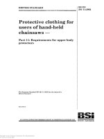
3.2
semi-automatic horizontal cutting cross-cut sawing machine with one saw unit (radial arm saw)
machine where the saw unit has integrated feed and moves horizontally forward on an arm in a straight line
during the cutting stroke and then back to its rest position
Note 1 to entry:
The arm can pivot relative to the centre line of its vertical support and the saw unit can cant relative to
a horizontal line in direction of the arm (see Figure 1), the work-piece is positioned manually or by means of a positioning
mechanism and integrated feed of saw unit is initiated manually.
NOTE
Guards are not shown.
Figure 1 — Example of a horizontal cutting cross-cut sawing machine with one saw unit
(semi-automatic machine)
3.3
machine actuator
power mechanism used to effect motion of the machine
3.4
integrated feed on radial arm saws
power operated feed mechanism for the saw-blade and work-piece which is integrated with the machine and
where the saw unit with incorporated saw-blade and the work-piece are held and controlled mechanically
during the machining operation
10
BS EN 1870-11:2013
EN 1870-11:2013 (E)
3.5
stationary machine
machine designed to be located on or fixed to the floor or other parts of the structure of the premises and to
be stationary during use
3.6
cutting area of the saw-blade
area where the saw-blade can be involved in the cutting process
3.7
non-cutting area of the saw-blade
area of the saw-blade where the saw-blade is not involved in the cutting process
3.8
cutting area of a semi-automatic radial arm saw
area defined by all possible positions in front of the fence of the saw-blade with the maximum diameter for
which the machine is designed, taking into account the saw unit's ability to cant or pivot for angled cutting and
the maximum cutting stroke and cutting depth
3.9
run-up time
time elapsed from the actuation of the start control device until the spindle reaches the intended speed
3.10
un-braked run-down time
time elapsed from the actuation of the stop control, but not the braking device (if fitted) up to spindle standstill
3.11
braked run-down time
time elapsed from the actuation of the stop control and the brake device up to spindle standstill
3.12
manual loading of power fed machines
operation where the work-piece is presented by the operator directly to the machine integrated feed, e.g.
rotating feed rollers, travelling table or reciprocating carriage; i.e. for which there is no intermediate loading
device to receive and transfer the work-piece from the operator to the integrated feed
3.13
manual unloading of power fed machines
operation where the work-piece is removed by the operator directly from the machine out feed; i.e. for which
there is no intermediate unloading device to receive and transfer the work-piece from the machine out feed to
the operator
3.14
information from the supplier
statements, sales literature, leaflets or other documents where a manufacturer (supplier) declares either the
characteristics or the compliance of the material or product to a relevant standard
3.15
performance level (PL)
discrete level used to specify the ability of safety-related parts of control systems to perform a safety function
under foreseeable conditions
[SOURCE: EN ISO 13849-1:2008, 3.1.23]
11
BS EN 1870-11:2013
EN 1870-11:2013 (E)
4
List of significant hazards
This clause contains all significant hazards, hazardous situations and events (see EN ISO 12100:2010),
identified by risk assessment as significant for the machines as defined in the scope and which require action
to eliminate or reduce the risk. This document deals with these significant hazards by defining safety
requirements and/or measures or by reference to relevant standards.
These hazards are listed in Table 1.
Table 1 — List of significant hazards
No
1
Hazards, hazardous situations and
hazardous events
EN ISO 12100:2010
Relevant
subclause of
this document
Mechanical hazards related to:
- machine parts or workpieces:
a) shape;
6.2.2.1, 6.2.2.2, 6.3
5.3.3, 5.3.6,
5.3.7, 5.4 11
b) relative location;
5.2.2, 5.2.5,
5.3.6, 5.3.7.3,
5.3.8, 5.4.5,
5.4.13
c) mass and stability (potential energy of
elements which may move under the
effect of gravity)
5.3.1
d) mass and velocity (kinetic energy of
elements in controlled or uncontrolled
motion);
5.3.7.3
e) mechanical strength.
5.3.2, 5.3.3
- accumulation of energy inside the machinery:
g) liquids and gases under pressure;
12
6.2.10, 6.3.5.4
5.4.6, 5.4.7
1.1
Crushing hazard
5.3.7, 5.3.8
1.2
Shearing hazard
5.3.7, 5.3.8
1.3
Cutting or severing hazard
5.3.2, 5.3.3,
5.3.4, 5.3.7
1.4
Entanglement hazard
5.3.7
1.5
Drawing-in or trapping hazard
5.3.7
1.6
Impact hazard
5.3.7.3, 5.3.7.4
1.8
Friction or abrasion hazard
5.3.4
1.9
High pressure fluid injection or ejection
hazard
5.3.4, 5.3.8,
5.4.6, 5.4.7,
5.4.13, 6.3
2
Electrical hazards due to:
2.1
Contact of persons with live parts (direct
contact)
6.2.9, 6.3.5.4
5.4.4, 5.4.12,
5.4.13
2.2
Contact of persons with parts which have
become live under faulty conditions
(indirect contact)
6.2.9
5.4.4, 5.4.12,
5.4.13
2.4
Electrostatic phenomena
5.4.10
BS EN 1870-11:2013
EN 1870-11:2013 (E)
Table 1 (continued)
4
Hazards generated by noise, resulting in:
4.1
Hearing
loss
(deafness),
other
physiological disorders (loss of balance,
loss of awareness)
4.2
Interference with speech communication,
acoustic signals.
6
Hazards generated by radiation
6.5
Lasers
7
Hazards generated by materials and substances (and their constituent elements)
processed or used by the machinery
7.1
Hazards from contact with or inhalation of
harmful fluids and dusts
6.2.3, 6.2.4
5.4.3, 6.3
7.2
Fire hazard
6.2.4
5.4.1, 5.4.3
8
Hazards generated by neglecting ergonomic principles in machinery design
related to:
8.1
Unhealthy postures or excessive effort
6.2.7, 6.2.8, 6.2.11.12,
6.3.5.5, 6.3.5.6
5.2.2, 5.4.5, 6.3
8.2
Hand-arm or foot-leg anatomy
6.2.8.3
5.2.2, 5.4.5, 6.3
8.4
Local lighting
6.2.8.6
6.3
8.6
Human error, human behaviour
6.2.8, 6.2.11.8,
6.2.11.10, 6.3.5.2, 6.4
6.3
8.7
Design, location
manual controls
6.2.8.7, 6.2.11.8
5.2.2
8.8
Design or location of visual display units
6.2.8.8, 6.4.2
5.2.2
9
Combination of hazards
6.3.2.1
5.2.3, 5.2.6,
5.2.7, 5.2.8,
5.3.7.4, 5.4.3,
5.4.4
10
Unexpected start up, unexpected overrun/overspeed (or any similar malfunction)
from:
10.1
Failure/disorder of the control system
6.2.11, 6.3.5.4
5.2.7, 5.2.8,
5.3.3.1
10.2
Restoration of energy supply after an
interruption
6.2.11.4
5.2.7, 5.2.8,
5.3.4, 5.4.6,
5.4.7
10.3
External
influences
equipment
6.2.11.11
5.4.4, 5.4.8
10.6
Errors made by the operator (due to
mismatch of machinery with human
characteristics and abilities, see 8.6)
6.2.8, 6.2.11.8,
6.2.11.10, 6.3.5.2, 6.4
5.2.1, 5.4.5, 6.3
11
Impossibility of stopping the machine
in the best possible conditions
6.2.11.1, 6.2.11.3,
6.3.5.2
5.2.2, 5.2.4,
5.2.5
13
Failure of the power supply
6.2.11.1, 6.2.11.4
5.2.7, 5.2.8,
5.3.4, 5.4.6,
5.4.7
6.2.2.2, 6.3
5.4.2, 6.3
6.3.4.5
or
identification
on
of
electrical
5.4.2, 6.3
5.4.9
13
BS EN 1870-11:2013
EN 1870-11:2013 (E)
Table 1 (continued)
5
14
Failure of the control circuit
6.2.11, 6.3.5.4
5.2.1
15
Errors of fitting
6.2.7, 6.4.5
5.3.3, 5.4.11,
6.1, 6.3
16
Break-up during operation
6.2.3
5.3.2
17
Falling or ejected objects or fluids
6.2.3, 6.2.10
5.2.3, 5.2.6,
5.3.2, 5.3.3,
5.3.5, 5.3.6,
5.3.8
18
Loss of stability / overturning of
machinery
6.3.2.6
5.3.1
Safety requirements and/or measures
5.1 General
The machine shall comply with the safety requirements and/or protective measures of this clause.
In addition, the machine shall be designed according to the principles of EN ISO 12100:2010, Clause 5 and
Clause 6, for hazards relevant but not significant, which are not dealt with by this document (e.g. sharp
edges).
For guidance in connection with risk reduction by design, see EN ISO 12100:2010, 6.2, and for safeguarding
measures, see EN ISO 12100:2010, 6.3.
5.2 Controls
5.2.1
Safety and reliability of control systems
For the purposes of this document, a safety related control system is one from and including the initial manual
control or position detector to the point of input to the final actuator or element, e.g. motor. Safety related parts
of the control system of this machine comprise parts concerning the following functions and they shall fulfil at
least the requirements of the PL given below in accordance with the requirements of EN ISO 13849-1:2008:
—
starting and restarting: PL = c (see 5.2.3);
—
normal stopping: PL = c (see 5.2.4);
—
emergency stop: PL = c (see 5.2.5);
—
moveable interlocked guards: PL = c (see 5.2.3, 5.3.7);
—
moveable interlocked guards with guard locking: PL = c (see 5.2.3 and 5.3.7);
—
interlocking of the cutting stroke with saw-blade rotation and work-piece clamping: PL = c (see 5.2.3);
—
mode selection: PL = c (see 5.2.7);
—
the initiation of the braking system: PL = b (see 5.2.4, 5.2.5 and 5.3.4);
—
the two-hand control device: PL = c (see 5.2.3 and 5.3.7);
14
BS EN 1870-11:2013
EN 1870-11:2013 (E)
—
on semi-automatic machines interlocking of self closing power operated guards with the position of the
saw unit: PL = c (see 5.3.7.1);
—
the active opto-electronic protective devices (light barriers): PL = c (see 5.3.7.4);
—
the pressure sensitive mats: PL = c (see 5.3.7.4);
—
the mechanically actuated trip devices (trip bar): PL = c (see 5.3.7.4);
—
the work-piece clamping: PL = c (see 5.3.8).
Time delay devices shall be PL = c in accordance with the requirements of EN ISO 13849-1:2008.
Verification: By checking the relevant drawings and/or circuit diagrams and inspection of the machine.
NOTE
5.2.2
For components characteristics the information from the component supplier can be useful.
Position of controls
The main electrical controls for starting the saw-blade spindle drive motor and normal stopping shall be
located together on the machine either:
a)
below the work-piece support; or
b)
on a control panel positioned:
1)
behind and above the fence; and
2)
within 850 mm measured horizontally from the front edge of the work-piece support; and
3)
at a maximum height of 1 600 mm from the floor level.
The two-hand control device to control the cutting stroke (also see 5.2.3) shall be situated:
c)
at the front of the machine within 1,0 m of the cutting line when it is at 90° to the fence;
d)
below the work-piece support;
e)
at a minimum height above floor level of 750 mm.
Where the control for the clamps is separate from the two-hand control device it shall be within 400 mm
measured horizontally to the two hand control device.
For the positioning of the emergency stops see 5.2.5.
Verification: By checking the relevant drawings, measurement and inspection of the machine.
5.2.3
Starting
Before starting or restarting the machine all the safeguards shall be in place and functional. This is achieved
by the interlocking arrangements described in 5.3.7. Start or restart shall only be possible by actuation of the
start control device provided for that purpose.
15
BS EN 1870-11:2013
EN 1870-11:2013 (E)
The initiation of the cutting stroke shall only be possible after saw-blade rotation and work-piece clamping
have been initiated.
The saw unit cutting stroke shall be controlled by a two-hand control device of at least type III B in accordance
with the requirements of EN 574:1996+A1:2008.
All reset controls shall be located outside protected areas and not reachable when standing inside a protected
area.
For electrically started machines
EN 60204-1:2006, 9.2.4 do not apply.
see
EN 60204-1:2006,
9.2.5.2.
The
exceptions
described
in
The safety related part of the control systems (also see 5.2.1) for starting and the interlocking arrangements
shall be at least PL = c in accordance with the requirements of EN ISO 13849-1:2008.
Verification: By checking the relevant drawings and/or circuit diagrams, measurement, inspection and relevant
functional testing of the machine.
5.2.4
Normal stopping
The machine shall be fitted with a stop control system, which when actuated shall disconnect power from all
machine actuators unless STO is used and actuate the brake (if provided).
For normal stopping of PDS(SR) (power drive system, safety related) see EN 61800-5-2:2007, 4.2.2.2 “safe
torque off (STO)” and 4.2.2.3 “safe stop 1 (SS1)”.
This stop control shall be of category 1 in accordance with the requirements of EN 60204-1:2006, 9.2.2. When
initiated the stopping sequence shall be:
a)
initiate the return stroke of the saw unit;
b)
remove power to work-piece clamping;
c)
cut power to saw spindle drive motor and initiate the brake (where fitted);
d)
when braking sequence is complete, cut power to brake (if electrical brake is fitted).
The stopping sequence shall be satisfied at the level of the control systems. If a time delay device is used,
time delay shall be at least the maximum run-down time. Either the time delay shall be fixed, or the time delay
adjustment device shall be sealed.
The safety related part of the control systems (also see 5.2.1) for normal stopping shall be at least PL = c in
accordance with the requirements of EN ISO 13849-1:2008.
Verification: By checking the relevant drawings and/or circuit diagrams, inspection and relevant functional
testing of the machine.
5.2.5
Emergency stop
The requirements of EN ISO 13850:2008 apply and in addition:
The machine shall be fitted with an emergency stop control system which shall conform to the requirements of
EN 60204-1:2006, 9.2.5.4 and 10.7. However, the requirements of EN 60204-1:2006 do not apply. The
emergency stop control device shall be at any time of self latching type.
16
BS EN 1870-11:2013
EN 1870-11:2013 (E)
For emergency stop of PDS(SR), see EN 61800-5-2:2007, 4.2.2.2 “safe torque off (STO)” and 4.2.2.3 “safe
stop 1 (SS1)”.
Depending on the size of the machine, the emergency stop(s) shall be positioned:
a)
within 1,0 m of the loading position;
b)
within 1,0 m of the unloading position;
c)
at the main control panel;
d)
within 500 mm of the two-hand control device (where fitted);
e)
within 3,0 m of the saw unit.
A single emergency stop can be positioned to fulfil more than one of these requirements.
When actuated the emergency stop shall disconnect power from all machine actuators and actuate the brake
(if provided).
The emergency stop control shall be of category 1 in accordance with the requirements of EN 60204-1:2006,
9.2.2. When initiated the stopping sequence shall be:
f)
initiate the return stroke of the saw unit;
g)
cut power to the saw spindle drive motor and initiate the brake (where fitted);
h)
when braking sequence is complete, cut power to brake (if electrical brake is fitted).
The stopping sequence shall be satisfied at the level of the control systems. If a time delay device is used,
time delay shall be at least the maximum run-down time. Either the time delay shall be fixed, or the time delay
adjustment device shall be sealed.
The safety related part of the control systems (also see 5.2.1) for the emergency stop shall be at least PL = c
in accordance with the requirements of EN ISO 13849-1:2008.
Verification: By checking relevant drawings and/or circuit diagrams, measurement, inspection and relevant
functional testing of the machine.
5.2.6
Integrated feed
The integrated feed of the work-piece positioning mechanism shall only operate when the saw unit is in its rest
position.
For the integrated feed of the saw unit, see 5.2.3.
Verification: By checking relevant drawings and/or circuit diagrams, inspection and relevant functional testing
of the machine.
5.2.7
Failure of the power supply
On electrically driven machines an automatic restart in the case of a supply interruption after the restoration of
the supply voltage shall be prevented in accordance with the requirements of EN 60204-1:2006, 7.5
paragraphs 1 and 3.
17
BS EN 1870-11:2013
EN 1870-11:2013 (E)
In the event of loss of pneumatic or hydraulic pressure, clamping of the work-piece shall be maintained until
the return stroke of the saw-blade is initiated. Where non-return valves are used to meet this requirement,
they shall be fitted to the actuating cylinders.
The automatic restart of the machine shall be prevented after restoration of the pneumatic or hydraulic energy.
Verification: By checking the relevant drawings and/or circuit diagrams, inspection and relevant functional
testing of the machine.
5.2.8
Failure of the control circuits
The requirements of EN 1037:1995+A1:2008 apply and in addition:
The control circuits shall be designed so that a break in any circuit (e.g. broken wire, ruptured pipe or hose)
will not result in the loss of a safety function, e.g. involuntary start of the machine or loss of work-piece
clamping (also see EN 60204-1:2006, EN ISO 4413:2010 and EN ISO 4414:2010).
Also see 5.2.1.
Verification: By checking the relevant drawings and/or circuit diagrams, inspection and relevant functional
testing on the machine.
5.3 Protection against mechanical hazards
5.3.1
Stability
It shall be possible to fix stationary machines to a suitable stable structure, e.g. floor. Facilities for fixing are,
e.g. fixing holes in the machine frame (also see 6.3).
Verification: By checking relevant drawings, inspection and relevant functional testing of the machine.
5.3.2
Risk of break up during operation
The guards for the saw-blade shall be manufactured from either:
−2
and a wall thickness of at least 1,5 mm;
a)
steel having an ultimate tensile strength of at least 350 N mm
b)
light alloy with characteristics in accordance with the requirements of Table 2;
Table 2 — Light alloy saw-blade guard thickness and tensile strength
Ultimate tensile strength
N mm
Minimum thickness
−2
mm
180
5
240
4
300
3
c)
polycarbonate with a wall thickness of at least 3 mm or other plastic material passing the test given in
Annex B;
d)
cast iron with an ultimate tensile strength of at least 200 N mm
18
−2
and a wall thickness of at least 5 mm.
BS EN 1870-11:2013
EN 1870-11:2013 (E)
Verification: By checking the relevant drawings, measurement, for plastic materials with characteristics other
than those given for polycarbonate in c) above by performing the test in Annex B and inspection on the
machine.
NOTE
5.3.3
For the ultimate tensile strength a confirmation from the manufacturer of the material can be useful.
Tool holder and tool design
The requirements of EN 847-1:2013 apply and in addition:
5.3.3.1
Spindle locking
When it is necessary to hold the spindle stationary for saw-blade changing, a spindle holding device shall be
provided, e.g. a double spanner arrangement or an integral locking bar inserted through the spindle. If a
locking bar is used it shall have a minimum diameter of 8 mm and be made from steel with a minimum
−2
ultimate tensile strength of 350 N mm .
Locking bars shall prevent the spindle from rotating if the spindle drive motor is inadvertently switched on.
Verification: By checking the relevant drawings, inspection, measurement and relevant functional testing of the
machine. Alternatively on machines with locking bars by the following test: after starting the spindle drive
motor with the locking bar in place the spindle shall remain stationary and shall not be deformed.
NOTE
For the ultimate tensile strength a confirmation from the manufacturer of the material can be useful.
5.3.3.2
Saw-blade fixing device
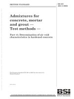
Saw flanges (or in the case of a flush mounted saw-blade - a flange) shall be provided.
For saw-blades with a diameter ≤ 450 mm the diameter of both flanges (or flange for flush mounting) shall be
at least D/4 (where D = the diameter of the largest saw-blade for which the machine is designed).
For saw-blades with a diameter > 450 mm, the diameter of the flanges shall be at least D/6, but not less than
115 mm.
For flanges other than those for flush mounted saw-blades the clamping surface at the outside part of flange
shall be at least 5 mm in width and recessed to the centre (see Figure 2).
Where two flanges are provided, both outside diameters shall be within a tolerance of ± 1 mm.
Precautions shall be taken to ensure that the saw-blade does not come loose during start-up, running, rundown or braking, e.g. by using a positive connection between the spindle and the saw-blade, or by using a
positive connection between the front saw flange and the saw spindle.
Saw spindles shall be manufactured in accordance with the tolerances given in Annex A.
Verification: By checking the relevant drawings, measurement and inspection of the machine.
19
BS EN 1870-11:2013
EN 1870-11:2013 (E)
Dimensions in millimetres
Figure 2 — Saw flange detail
5.3.4
Braking
An automatic brake shall be provided for the saw spindle on semi-automatic machines where the un-braked
run-down time exceeds 10 s. The braked run-down time shall be less than 10 s or where the run up time is
exceeds 10 s be less than the run up time but in no case shall exceed 30 s.
NOTE 1
In the case of failure of power supply this run-down time may be exceeded.
A PLr of at least c for the braking function shall be achieved.
The braking torque shall not be applied directly to the saw blade itself or the saw blade flange(s).
Where a spring operated mechanical brake or any other type of brake not using electronic components is
fitted the last paragraph of EN 60204-1:2006, 9.3.4 does not apply (see 6.3).
For electrical braking, reverse current injection braking shall not be used.
As an exception where an electrical brake with electronic control system is fitted, its control system shall be
designed, as a minimum, in PL = b in accordance with the requirements of EN ISO 13849-1:2008 and be
designed in category 2 in accordance with the requirements of EN ISO 13849-1:2008 with the exception that
the test rate requirement in EN ISO 13849-1:2008, 4.5.4 is not applicable. The safety related part of the
control system for braking shall be tested periodically, e.g. by monitoring braked run down time. The feed back
shall come from either the encoder fitted to the spindle motor or from the measurement of the residual current
in the wires powering the motor.
The test shall:
a)
be independent from the basic control system for braking or an internal watchdog function shall be
provided;
b)
be independent from the intention of the operator;
c)
be performed at each spindle stop.
Where the test result is negative more than three times in succession, it shall not be possible to operate the
machine. A negative test result shall be indicated.
20
BS EN 1870-11:2013
EN 1870-11:2013 (E)
The diagnostic coverage (DCavg) shall be ≥ 60 %.
See EN ISO 13849-1:2008, Annex E for DC estimation.
As an exception, a simple electronic brake (using simple electronic parts like rectifiers, transistors, triacs,
diodes, resistors, thyristors) may be PL = b and designed in category 1 in accordance with the requirements of
EN ISO 13849-1:2008 if the “mean time to a dangerous failure” (MTTFd) according to EN ISO 13849-1:2008,
Table 5 reaches a value of “high” (at least 30 years).
NOTE 2
Complex electronic components like, e.g. microprocessors or PLCs cannot be considered as well tried under
the scope of EN ISO 13849-1:2008 and do therefore not fulfil the requirements of category 1.
For calculating the probability of a dangerous failure for a simple electronic brake component with no fault
detection (no DC) and no testing capability (category 1) the procedure described in EN ISO 13849-1:2008,
Annex D can be used.
Verification: By checking the relevant drawings and/or circuit diagrams, inspection of the machine and relevant
functional testing of the machine. For the determination of un-braked run-down time and braked run-down
time, if relevant, the appropriate tests given in Annex C apply.
5.3.5
Devices to minimise the possibility or the effect of ejection
The direction of the rotation of the saw-blade shall be such, that the cutting force is directed against the fence.
Verification: By checking the relevant drawings and/or circuit diagrams, inspection and relevant functional
testing of the machine.
5.3.6
5.3.6.1
Work-piece supports and guides
Work-piece support
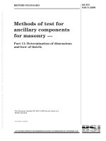
The machine shall be provided with a work-piece support (see Figure 3) which complies with the following
requirements:
a)
it shall extend at least 250 mm on each side of the cutting area (see 3.8);
b)
the width B (see Figure 3) shall be such that the front edge of the largest saw-blade for which the
machine is designed will not project beyond the work-piece support when the saw unit is at its maximum
forward position;
c)
the work-piece support in the cutting area shall be made from wood, wood based material, plastic or light
alloy;
d)
there shall be no table rollers inside the cutting area and within a distance of 250 mm to the cutting area.
Verification: By checking relevant drawings, inspection, measurement and relevant functional testing of the
machine.
21
BS EN 1870-11:2013
EN 1870-11:2013 (E)
Key
1
work-piece support (machine table)
2
saw-blade (adjusted to maximum pivoting and canting)
3
fence
B
width of the work-piece support
Α
maximum pivoting angle
Figure 3 — Dimensions of work-piece support (machine table)
5.3.6.2
Work-piece guides
The machine shall be provided with a vertical work-piece guide acting as a fence on each side of the cutting
line which complies with the following requirements:
a)
It shall be positioned at right angles to the non-pivoted saw unit.
b)
It shall not be capable of adjustment so that the saw-blade protrudes beyond the fence when the saw unit
is in the rest position.
c)
Taking account of the ability to rotate the saw unit about a vertical axis for angled cutting, that part of the
fence within 10 mm of the cutting line shall be made of, e.g. wood, plastic or light alloy.
d)
The fence shall have a height of at least 50 % of the maximum depth of cut for which the machine is
designed, except for an area to allow passage of the saw blade but not less than 60 mm.
Verification: By checking relevant drawings, inspection, measurement and relevant functional testing of the
machine.
5.3.7
5.3.7.1
Prevention of access to moving parts
Guarding of the saw-blade and saw unit
Access to the non-cutting area of the saw-blade shall be prevented by a fixed guard extending to the central
axis of the saw spindle.
22
BS EN 1870-11:2013
EN 1870-11:2013 (E)
If the fixed guards are to be demounted by the user, e.g. for maintenance, their fixing systems shall remain
attached to the guards or to the machinery when the guards are removed, e.g. with un-losable screws, see
6.3 x).
Where access is required for saw-blade changing the access component shall be a moveable guard hinged to
the fixed guard and interlocked with the spindle drive motor. As an alternative a fixed guard shall be provided
which shall only be capable of being removed with the aid of a tool and whose fixings shall remain fixed to the
machine in accordance with EN 953:1997+A1:2009, 7.2. The guard shall not remain in place without its fixing.
When the saw unit is in its rest position access to the cutting area of the saw-blade shall be prevented either
by:
a)
fixed guards if they are to be demounted by the user, e.g. for maintenance, their fixing systems remaining
attached to the guards or to the machinery when the guards are removed, e.g. with un-losable screws,
see 6.3 x). Any openings in fixed guards shall be so designed that the safety distances shown in
EN ISO 13857:2008, Table 4 are met; or
b)
self closing power operated guards; or
c)
a combination of fixed guards and self closing power operated guards.
Where self closing power operated guards are fitted they shall be interlocked with the position of the saw unit.
Direct access from the rear of the machine to any crushing or shearing hazard created by the saw unit return
stroke shall be prevented by fixed guards, any openings in which shall be so designed that the safety
distances shown in EN ISO 13857:2008, Table 4 are met.
The cutting stroke of the saw unit shall be controlled by the two-hand control device required in 5.2.3. When
this control is released the saw unit shall return to the rest position within 1,5 s.
The safety related part of the control systems (also see 5.2.1) for two hand control and interlocking function
shall be at least PL = c in accordance with the requirements of EN ISO 13849-1:2008.
Verification: By checking relevant drawings and/or circuit diagrams, inspection, measurement and relevant
functional testing of the machine.
5.3.7.2
5.3.7.2.1
Guarding of work-piece positioning mechanisms
General
Except in the loading and unloading area, access to the dangerous parts (e.g. crushing or shearing hazards)
of the work-piece positioning mechanism shall be prevented either by a fixed guard or by a movable
interlocked guard with guard locking.
If the fixed guards are to be demounted by the user, e.g. for maintenance, their fixing systems shall remain
attached to the guards or to the machinery when the guards are removed, e.g. with un-losable screws, see
6.3 x).
−1
In the loading and unloading area access to points with impact hazard (i.e. feed speed ≥ 25 m min ) and to
points with drawing in or shearing hazards shall be avoided by the provision of either:
a)
fixed guards if they are to be demounted by the user, e.g. for maintenance or cleaning purposes their
fixing systems remaining attached to the guards or to the machinery when the guards are removed, e.g.
with un-losable screws see 6.3 x) or moveable interlocked guards with guard locking and at least
23