Bsi bs en 01991 1 5 2003 (2004) na 2007
Bạn đang xem bản rút gọn của tài liệu. Xem và tải ngay bản đầy đủ của tài liệu tại đây (948.94 KB, 18 trang )
Un
i
t
e
dKi
n
g
d
o
mo
fGr
e
a
t
Br
i
t
a
i
na
n
dNo
r
t
h
e
r
nI
r
e
l
a
n
d
≠ EDI
CTOFGOVERNMENT±
I
no
r
d
e
rt
op
r
o
mo
t
ep
u
b
l
i
ce
d
u
c
a
t
i
o
na
n
dp
u
b
l
i
cs
a
f
e
t
y
,e
q
u
a
lj
u
s
t
i
c
ef
o
r
a
l
l
,ab
e
t
t
e
ri
n
f
o
r
me
dc
i
t
i
z
e
n
r
y
,t
h
er
u
l
eo
fl
a
w,wo
r
l
dt
r
a
d
ea
n
dwo
r
l
d
p
e
a
c
e
,t
h
i
sl
e
g
a
ld
o
c
u
me
n
ti
sh
e
r
e
b
yma
d
ea
v
a
i
l
a
b
l
eo
nan
o
n
c
o
mme
r
c
i
a
l
b
a
s
i
s
,a
si
ti
st
h
er
i
g
h
to
fa
l
lh
u
ma
n
st
ok
n
o
wa
n
ds
p
e
a
kt
h
el
a
wst
h
a
t
g
o
v
e
r
nt
h
e
m.
BS NA EN 1991-1-5 (2003) (English): UK National
Annex to Eurocode 1. Actions on structures.
General actions. Thermal actions
Nu
l
l
iv
e
n
d
e
mu
s
,n
u
l
l
in
e
g
a
b
i
mu
sa
u
td
i
f
f
e
r
e
mu
sRe
c
t
u
ma
u
tJu
s
t
i
c
i
a
m.
Wewi
l
ls
e
l
lt
on
oma
n
,wewi
l
ln
o
td
e
n
yo
rd
e
f
e
rt
oa
n
yma
ne
i
t
h
e
rJu
s
t
i
c
eo
rRi
g
h
t
.
MAGNACARTA(
1
2
97
)
NA to BS EN 1991-1-5:2003
NATIONAL ANNEX
UK National Annex to
Eurocode 1: Actions on
structures Part 1-5: General actions - Thermal
actions
Ies 91.010.30
British Standards
NO COPYING WITHOUT BSI PERMISSION EXCEPT AS PERMITTED BY COPYRIGHT LAW
NA to BS EN 1991-1-5:2003
Publishing and copyright information
The BSI copyright notice displayed in this document indicates when the
document was last issued.
© BSI 2007
ISBN 978 0 580 50575 1
The following BSI references relate to the work on this standard:
Committee reference B/525/1
Draft for comment 06/30128336DC
Publication history
First edition April 2007
Amendments issued since publication
Amd. no.
Date
Text affected
NA to BS EN 1991-1-5:2003
Contents
Introduction 1
NA.l
NA.2
NA.3
Scope 1
Nationally Determined Parameters 1
Decisions on the status of BS EN 1991-1-5:2003 informative
annexes C and D 7
Bibliography 10
List of figures
Figure NA.1 - Isotherms of minimum shade air temperature COC) 8
Figure NA.2 - Isotherms of maximum shade air temperature COC) 9
List of tables
Table NA.1 - Adjustment to uniform bridge temperature for deck
surfacing 3
Summary of pages
This document comprises a front cover, an inside front cover,
pages i and ii, pages 1 to 10, an inside back cover and a back cover.
â BSI 2007
ã
NA to BS EN 1991-1-5:2003
ii ·
© BSI 2007
This page deliberatel:y left blank
NA to BS EN 1991-1-5:2003
National Annex (inforInative)
to BS EN 1991-1-5:2003,
Actions on structures Part 1-5: General actionsTherInal actions
Introduction
This National Annex has been prepared by BSI Subcommittee B/525/l,
Actions (loadings) and basis of design. In the UK it is to be used in
conjunction with BS EN 1991-1-5:2003.
NA.l Scope
This National Annex gives:
a)
the UK decisions for the Nationally Determined Parameters
described in the following sub clauses of BS EN 1991-1-5:2003
- 5.3(2)
- 6.1.4.2(1)
- 7.2.1(1)
- 6.1.1(1)
- 6.1.4.3(1)
-
- 6.1.2(2)
- 6.1.4.4(1)
-7.5(4)
- 6.1.3.1(4)
- 6.1.5(1)
- A.1(1)
- 6.1.3.2(1)
- 6.1.6(1)
-A.1(3)
6.1.3.3(3)
- 6.1.4(3)
- 6.1.4.1(1)
- 6.2.1(1)P
6.2.2(1)
7.5(3)
A.2(2)
-B(l)
- 6.2.2(2)
b) the UK decisions on the status ofBS EN 1991-1-5:2003
informative annexes C and D (see NA.3); and
c)
references to non-contradictory complementary information.
NA.2 Nationally Determined Parameters
NA.2.1
Determination of temperature profiles
[BS EN 1991-1-5:2003, 5.3(2)]
The values recommended in BS EN 1991-1-5: 2003, Table 5.1, should be
used.
The values recommended inBSEN 1991-1-5:2003, Table 5.2, should be
used, except that the minimum shade air temperature T min and the
maximum shade air temperature Tma:x should be obtained from
Figure NA.1 and Figure NA.2, respectively.
The values recommended in BS EN 1991-1-5:2003, Table 5.3, should be
used.
â BSI 2007
ã
1
NA to BS EN 1991-1-5:2003
NA.2.2
NA.2.2.1
Bridge deck types
[BS EN 1991-1-5:2003, 6.1.1(1), NOTE 2]
General
Values for the uniform temperature component and temperature
difference component for buried concrete box and portal frame
structures, and masonry arch bridges with solid spandrels, are given in
NA.2.2.2 and NA.2.2.3.
Values for other types of bridges not covered in BS EN 1991-1-5 should
be agreed for the individual project with the relevant authority, where
appropriate.
The following may be considered to be protected from climatic and
operational temperature changes:
a)
the walls and base slab of buried concrete box structures and the
walls of buried concrete portal frame structures;
b) in situ buried concrete structures which have over 0,6 metres of
cover Cfill plus surfacing) and which are more than five times as
long Ctransversely) as the clear span or, for multispan structures,
five times as long as the largest clear span;
c)
precast buried concrete segments which have over 0,6 metres
of cover Cfill plus surfacing) and which are located more
than 1,25 times the clear span from the edge of the structure.
Buried concrete box and portal frame structures, and masonry arch
bridges with solid spandrels, should be classified as Type 3 structures.
NA.2.2.2
Uniform temperature component
For buried concrete box and portal frame structures, and masonry arch
bridges with solid spandrels, where the total cover depth from the top
of the surfacing to the top of the roof slab or extrados of the arch ring
is greater than 200 mm, the minimum and maximum uniform bridge
temperatures obtained from BS EN 1991-1-5:2003, Figure 6.1, and
adjusted using Table NA.1 may be further modified as follows:
For every additional 100 mm of total cover depth in excess
of 200 nun:
a) the minimum uniform bridge temperature may be increased
by 1°C;
b) the maximum uniform bridge temperature may be reduced
by 2°C.
However, the difference between the maximum and minimum
uniform bridge temperature should not be taken as less than 15°C.
Changes in uniform bridge temperature may be ignored when the total
depth from the top of the surfacing to the top of the roof slab or
extrados of the arch ring is 1,5 m or greater.
2 ã
â BSI 2007
NA to BS EN 1991-1-5:2003
NA.2.2.3
Temperature difference component
BS EN 1991-5:2003, Annex B, should be used to establish temperature
differences for buried concrete box and portal frame structures, and
masonry arch bridges with solid spandrels. In BS EN 1991-5:2003,
Table B.3, the value of h for buried concrete structures should be taken
as the distance from the underside of the surfacing to the soffit of the
roof slab. For masonry arch bridges the value of h in Table B.3 should
be taken as the distance from the underside of the surfacing to the
intrados of the arch ring. In BS EN 1991-5:2003, Figure 6.2a,
Figure 6.2b and Figure 6.2c, LlT 1 should be taken as occurring at the
underside of the surfacing and the dimensions h and hI should be
measured downwards from that level so that the temperature profiles
shown in BS EN 1991-5:2003, Figure 6.2c, are applied through the fill
as well as through the roof slab or arch ring.
Heating and cooling temperature differences may be ignored when the
total depth from the top of the surfacing to the top of the roof slab or
extrados of the arch ring exceeds 500 mm.
NA.2.3
Consideration of thermal actions
[BS EN 1991-1-5:2003, 6.1.2(2)]
Approach 2 should be used, unless the use of Approach 1 is agreed for
the individual project with the relevant authority.
NA.2.4
Uniform temperature components - General
[BS EN 1991-1-5:2003, 6.1.3.1(4)]
The values of Te .min and Te .max recommended in BS EN 1991-1-5:2003,
Figure 6.1, should be used, subject to the adjustments for deck
surfacing given in Table NA.1.
The uniform bridge temperature components are dependent on the
depth of surfacing on the bridge deck, and the values given in
BS EN 1991-1-5:2003, Figure 6.1, assume depths of 40 mm for Type 1
and 100 mm for Types 2 and 3. When the depth of surfacing differs from
these values, the minimum and n1aximum uniform bridge temperature
components should be adjusted by the amounts given in Table NA.1.
Table NA.1
Deck
surface
Adjustment to uniform bridge temperature for deck surfacing
Addition to minimum uniform bridge
temperature component, °C
Addition to maximum uniform bridge
temperature component, °C
Type 1
Type 1
Type 2
+4
+4
0
Type 2
Type 3
0
Water-proofed A)
0
40 mm surfacing B)
0
100 rnrn surfacing B)
N/A
N/A
200 mm surfacing B)
A)
B)
C)
-3
-1
-1
0
0
+3
+1
Type 3
+4
+2
0
+2
+1
N/A
N/A
0
0
C)
-2
Waterproofed deck values are conservative, assuming dark material; there may be some alleviation when light coloured
waterproofing is used; specialist advice should be sought if required.
Surfacing depths include waterproofmg.
For steel truss and plate girders the values for unsurfaced and waterproofed deck surfaces may be reduced to +2 °e.
BSI2007
•
3
NA to BS EN 1991-1-5:2003
NA.2.5
Shade air temperature
[BS EN 1991-1-5:2003, 6.1.3.2(1)]
The minimum and maximum shade air temperatures with a probability
of being exceeded of 0,02 (1 in 50 year return period) should be
obtained from the maps of isotherms in Figure NA.1 and Figure NA.2,
respectively.
NA.2.6
Range of uniform bridge temperature
component
[BS EN 1991-1-5:2003, 6.1.3.3(3)]
For bearings and expansion joints, the maximum expansion and
contraction ranges of the uniform bridge temperature component
should be as given by other relevant standards (for example,
BS EN 1993-2). Where no information is given the requirements should
be as follows:
(~TN,exp
+ 20) °C
and
(~TN,con
+ 20) °C,
respectively.
If the temperature at which the bearings and expansion joints are set is
specified then the ranges are (~TN,exp + 10) °C and (~TN,con + 10) °C,
respectively.
NA.2.7
Temperature difference components
[BS EN 1991-1-5:2003, 6.1.4(3)]
The initial temperature difference at the closure of cantilever
construction should be specified for the individual project.
NA.2.8
Vertical linear component (Approach 1)
[BS EN 1991-1-5:2003, 6.1.4.1(1)]
Generally, Approach 1 should not be used. However, where Approach 1
is specified and permitted for use, the values of ~TM,heat and ~TM,cool and
factor k sur given in BS EN 1991-1-5:2003, Table 6.1 and Table 6.2,
respectively, should be used.
NA.2.9
Vertical temperature components with
non-linear effects (Approach 2)
[BS EN 1991-1-5:2003, 6.1.4.2(1)]
The temperature difference values recommended in
BS EN 1991-1-5:2003, Figure 6.2a to Figure 6.2c, for the different
types of bridge deck should be used, but with the following changes to
Figure 6.2a and Figure 6.2c:
In Figure 6.2a:
•
4 • © BSI 2007
In note, ~TN should be ~Tu.
NA to BS EN 1991-1-5:2003
In Figure 6.2c:
Colunm (a) Heating: Table: the value of /).T1 for h ;:::: 0,8 should
be 13,5 instead of 13,0;
Column (b) Cooling: Figure: the top horizontal line for h3 should
be lowered to the kink;
•
Column (b) Cooling: Below figure: line 2:
of;:::: 0,20 m;
•
In note, /).TN should be /).Tu'
~
0,20 m instead
The data given in BS EN 1991-1-5:2003, Figure 6.2, assume depths of
surfacing of 40 mm for Type 1 and 100 mm for Types 2 and 3. For other
depths of surfacing different values will apply. Values for other
thicknesses of surfacing are given in BS EN 1991-1-5:2003, Annex B.
NA.2.10
Horizontal components
[BS EN 1991-1-5:2003, 6.1.4.3(1)]
Where a horizontal temperature difference needs to be considered, a
temperature difference between the outer edges of the bridge,
independent of the width of the bridge, of 5 °C may be used.
Alternatively, appropriate values may be determined from first
principles.
NA.2.11
Temperature difference components within
walls of concrete box girders
[BS EN 1991-1-5:2003, 6.1.4.4(1)]
The linear temperature difference of 15°C recommended in
BS EN 1991-1-5:2003, 6.1.4.4(1), Note, may be used. Alternatively,
appropriate non-linear distribution and corresponding values may be
determined from first principles.
NA.2.12
Simultaneity of uniform and temperature
difference components
[BS EN 1991-1-5:2003, 6.1.5(1)]
The values of (ON = 1,00 and (OM = 1,00 may be used. The ranges of
uniform bridge temperature component for expansion and contraction
(/).TN) should be determined from the relevant value of To and:
•
appropriate values of Te max above 25°C for Type 1 and Temax
above 15°C for Types 2 and 3.
•
appropriate values of Te min of up to 8 °C below the maximum for
Type 1
Te min of up to 4 °C below the maximum for
Type 2
Te min of up to 2 °C below the maximum for
Type 3.
Alternatively, appropriate values may be determined from first
principles.
â BSI 2007
ã
5
NA to BS EN 1991-1-5:2003
NA.2.13
Difference in the uniform temperature
components between different structural
elements [BS EN 1991-1-5:2003, 6.1.6(1)]
Where relevant, the values for the differences in the uniform
temperature component recommended in the note to
BS EN 1991-1-5:2003, 6.1.6(1), may be used.
Alternatively, appropriate values may be determined from first
principles.
NA.2.14
Consideration of thermal actions
[BS EN 1991-1-5:2003, 6.2.1(1)P]
The design procedure to be used for taking temperature differences
between the outer faces of bridge piers may assume an equivalent linear
tenlperature difference.
NA.2.15
Temperature differences
[BS EN 1991-1-5:2003, 6.2.2(1)]
The linear temperature difference between the opposite outer faces of
concrete piers may be taken as 5 ce. Alternatively, appropriate values
may be determined from first principles.
NA.2.16
Temperature differences
[BS EN 1991-1-5:2003, 6.2.2(2)]
The linear temperature difference between the inner and outer faces of
walls may be taken as 15 ce. Alternatively, appropriate values may be
determined from first principles.
NA.2.17
Shade air temperature
[BS EN 1991-1-5:2003, 7.2.1(1)]
The minimum and maximum shade air temperatures with a probability
of being exceeded of 0,02 (1 in 50 year return period) should be
obtained from the maps of isotherms given in Figure NA.l and
Figure NA.2, respectively.
NA.2.18
Values of temperature components (indicative
values) [BS EN 1991-1-5:2003, 7.5(3)]
The linear temperature difference component value of 15 ce
recommended in Note 1 to BS EN 1991-1-5:2003, 7.5(3), should be
used.
NA.2.19
Values of temperature components (indicative
values) [BS EN 1991-1-5:2003, 7.5(4)]
The value of stepped temperature component of 15 ce recommended in
the note to BS EN 1991-1-5:2003, 7.5(4), should be used.
6 ã
â BSI 2007
NA to BS EN 1991-1-5:2003
NA.2.20
Isotherms of national minimum shade air
temperatures - General
[BS EN 1991-1-5:2003, A.1(1)]
The minimum and maximum shade air temperatures are obtained from
the maps of isotherms in Figure NA.l and Figure NA.2, respectively.
These figures relate to a 0,02 probability exceedance (1 in 50 year
return period).
The temperature values should be adjusted for height above mean
sea level using the recommended method given in
BS EN 1991-1-5:2003, A.l(l), Note 2.
NA.2.21
Isotherms of national minimum and maximum
shade air temperatures - Gelleral
[BS EN 1991-1-5:2003, A.1(3)]
In the absence of specific provisions to control the temperature at which
a bridge is restrained, the initial temperature To should be taken as °C
for expansion and 20°C for contraction, except that, for buried
concrete box structures, the value of To may be taken as 10°C for both
expansion and contraction.
°
NA.2.22
Maximum and minimum shade air temperature
values with an annual probability of being
exceededp other than 0,02
[BS EN 1991-1-5:2003, A.2(2)]
The values ofkv k2' k 3 , k4should be taken as 0,781, 0,056, 0,393 and
-0,156, respectively, as recommended in BS EN 1991-1-5:2003,
A.2(2), Note 1.
NA.2.23
Temperature differences for various surfacing
depths [BS EN 1991-1-5:2003, B(l)]
Temperature difference profiles for surfacing depths, other than 40 mm
for Type 1 and 100 mm for deck Types 2 and 3, should be as given in
BS EN 1991-1-5:2003, Table B.l, Table B.2 and Table B.3, except with
the following changes to Table B.3:
•
1st colwnn: replace "0,2" with
0,2"
•
1st column: replace "1,5" with "~ 1,5"
•
6th column, 1,0 m depth of slab and 200 mm surfacing thickness:
replace "4,3" with "4,8".
NA.3 Decisions on the status of
BS EN 1991-1-5:2003 informative
annexes C and D
BS EN 1991-1-5:2003, informative annexes C and D, may be used in the
UK as informative annexes.
â BSI 2007
ã
7
NA to BS EN 1991-1-5:2003
Figure NA.l
Isothenns of minimum shade air temperature ee)
2
5
4
3
~bO
12
11
6
12
t -10
11
.,
~
ut -10
~l:IAb
__+-____
-+______+-____~10
10
9
-------r------r---__~----~9
I~------+------+------I
7
8
7
\~-----r_----~----~
3
~---+----I
6
5
~__:_;::+__--I 4
2
3
2
2
-7
o
__ 0
NATIONAL GRID 55
~------~----~--~~~--~~
LlTM GRID
54 3 ZONE 30U 4
NOTE The isotherms are derived from Meteorological Office Data.
8 ã
â BSI 2007
NA to BS EN 1991-1-5:2003
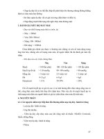
Figure NA.2
Isotherms of maximum shade air temperature eC)
2
4
3
5
6
-¥f-A-'"b-ou-t-24--+-----; 2
~1~1
__- - + ___
--+-~~-4_----~----~11
_____----------~-----r---------rO
10
~----_4--------r-----~--__~9
9
8
------~----+-----~
8
~.--~----~-----+--------17
7
~--~----_+------16
4
2
-...\-_ _--1-------1
5
'\or--+-----I
4
3
o
1
o
NATIONAL GRID r-5~S-----t------t----"
NOTE The isotherms are derived from Meteorological Office Data.
â BSI 2007
ã
9
NA to BS EN 1991-1-5:2003
Bibliography
Standards publications
BS EN 1337-1, Structural bearings - Part 1: General design rules
BS EN 1337-2, Structural bearings -Part 2: Sliding elements
BS EN 1337-3, Structural bearings -Part 3: Elasto1neric bearings
(in preparatian)
BS EN 1337-4, Structural bearings -Part 4: Roller bearings
BS EN 1337-5, Structural bearings -Part 5: Pot bearings
BS EN 1337-6, Structural bearings -Part 6: Rocker bearings (in
preparatian)
BS EN 1337-7, Structural bearings -Part 7: Spherical and
cylindrical PTFE bearings
BS EN 1990: 2002, Eurocode - Basis oj structural design
BS EN 1991 (all parts), Eurocode 1 - Actions on structures
BS EN 1993-2, Eurocode 3 -Design oJsteel structuresPart 2: Steel bridges
Other publications
Emerson, Mary. "Temperature differences in bridges: basis oj
design requirements. " Department of the Environment,
TRRL Report LR 765. Crowthorne, Berkshire, United Kingdom, 1977.
10 ã
â BSI 2007
NA to BS EN 1991-1-5:2003
This page deliberately left blank
NA to BS EN 1991-1-5:2003
BSI - British Standards Institution
BSI is the independent national body responsible for preparing British Standards.
It presents the UK view on standards in Europe and at the international level.
It is incorporated by Royal Charter.
Revisions
British Standards are updated by amendment or revision. Users of British Standards
should make sure that they possess the latest amendments or editions.
It is the constant aim of BSI to improve the quality of our products and services.
We would be grateful if anyone finding an inaccuracy or ambiguity while using this
British Standard would inform the Secretary of the technical committee responSible,
the identity of which can be found on the inside front cover.
Tel: +44 (0)208996 9000. Fax: +44 (0)20 8996 7400.
BSI offers members an individual updating service called PLUS which ensures that
subscribers automatically receive the latest editions of standards.
Buying standards
Orders for all BSI, international and foreign standards publications should be
addressed to Customer Services. Tel: +44 (0)2089969001.
Fax: +44 (0)208996 7001. Email: orders@bsi-globaLcom. Standards are also
available from the BSI website at .
In response to orders for international standards, it is BSI policy to supply the BSI
implementation of those that have been published as British Standards, unless
otherwise requested.
Information on standards
BSI provides a wide range of information on national, European and international
standards through its Library and its Technical Help to Exporters Service. Various
BSI electronic information services are also available which give details on all its
products and services. Contact the Information Centre. Tel: +44 (0)208996 7111.
Fax: +44 (0)20 8996 7048. Email: info@bsi-globaLcom.
Subscribing members of BSI are kept up to date with standards developments and
receive substantial discounts on the purchase price of standards. For details of these
and other benefits contact Membership Administration. Tel: +44 (0)20 8996 7002.
Fax: +44 (0)20 8996 7001. Email:
Information regarding online access to British Standards via British Standards
Online can be found at -globaLcorn/bsonline.
Further information about BSI is available on the BSI website at
-globaLcom.
Copyright
-.... ..- ~
........
•
British Standards
389 Chiswick High Road
London
W44AL
Copyright subsists in all BSI publications. BSI also holds the copyright, in the UK, of
the publications of the international standardization bodies. Except as permitted
under the Copyright, Designs and Patents Act 1988 no extract may be reproduced,
stored in a retrieval system or transmitted in any form or by any means - electronic,
photocopying, recording or otherwise - without prior written permission from BSI.
This does not preclude the free use, in the course of implementing the standard, of
necessary details such as symbols, and size, type or grade designations. If these
details are to be used for any other purpose than implementation then the prior
written permission of BSI must be obtained.
Details and advice can be obtained from the Copyright & Licensing Manager.
Tel: +44 (0)20 8996 7070. Fax: +44 (0)20 8996 7553.
Email: