Bsi bs en 10274 1999
Bạn đang xem bản rút gọn của tài liệu. Xem và tải ngay bản đầy đủ của tài liệu tại đây (369.21 KB, 12 trang )
I S B ) c( , y p o C d ell ort n o c nU , 7 0 0 2 0 0: 0 0+TM G 4 2: 1 0: 7 0 1 0 r aM u hT , yti sr e vi nU k n a B ht u o S n o d n oL , yti sr e vi nU k n a B ht u o S n o d n oL : y p o C d e s n e ciL
BRITISH STANDARD
Metallic materials Ð
Drop weight tear test
The European Standard EN 10274:1999 has the status of a
British Standard
ICS 77.040.10
NO COPYING WITHOUT BSI PERMISSION EXCEPT AS PERMITTED BY COPYRIGHT LAW
|
|
|
|
|
|
|
|
|
|
|
|
|
|
|
|
|
|
|
|
|
|
|
|
|
|
|
|
|
|
|
|
|
|
|
|
|
|
|
|
|
|
|
|
|
|
|
|
|
|
|
|
|
|
|
|
|
|
|
|
|
|
|
|
|
|
|
|
|
|
|
|
|
|
|
|
|
|
|
|
|
|
|
|
|
|
|
|
|
|
|
|
|
|
|
|
|
|
|
|
|
|
|
|
|
|
|
|
|
|
|
|
|
|
|
|
|
|
|
|
|
|
|
|
|
|
|
|
|
BS EN
10274:1999
I S B ) c( , y p o C d ell ort n o c nU , 7 0 0 2 0 0: 0 0+TM G 4 2: 1 0: 7 0 1 0 r aM u hT , yti sr e vi nU k n a B ht u o S n o d n oL , yti sr e vi nU k n a B ht u o S n o d n oL : y p o C d e s n e ciL
BS EN 10274:1999
National foreword
This British Standard is the English language version of EN 10274:1999.
The UK participation in its preparation was entrusted by Technical Committee
ISE/NFE/4, Mechanical testing of metals, to Subcommittee ISE/NFE/4/2, Ductility
tests, which has the responsibility to:
Ð aid enquirers to understand the text;
Ð present to the responsible European committee any enquiries on the
interpretation, or proposals for change, and keep the UK interests informed;
Ð monitor related international and European developments and promulgate
them in the UK.
A list of organizations represented on this subcommittee can be obtained on request
to its secretary.
Cross-references
The British Standards which implement international or European publications
referred to in this document may be found in the BSI Standards Catalogue under the
section entitled ªInternational Standards Correspondence Indexº, or by using the
ªFindº facility of the BSI Standards Electronic Catalogue.
A British Standard does not purport to include all the necessary provisions of a
contract. Users of British Standards are responsible for their correct application.
Compliance with a British Standard does not of itself confer immunity
from legal obligations.
Summary of pages
This document comprises a front cover, an inside front cover, the EN title page,
pages 2 to 8, an inside back cover and a back cover.
The BSI copyright notice displayed throughout this document indicates when the
document was last issued.
This British Standard, having
Amendments issued since publication
been prepared under the
direction of the Engineering
Sector Committee, was published
under the authority of the
Standards Committee and comes
into effect on 15 September 1999
©
BSI 09-1999
ISBN 0 580 32638 1
Amd. No.
Date
Comments
I S B ) c( , y p o C d ell ort n o c nU , 7 0 0 2 0 0: 0 0+TM G 4 2: 1 0: 7 0 1 0 r aM u hT , yti sr e vi nU k n a B ht u o S n o d n oL , yti sr e vi nU k n a B ht u o S n o d n oL : y p o C d e s n e ciL
EN 10274
EUROPEAN STANDARD
 ENNE
NORME EUROPE
È ISCHE NORM
EUROPA
May 1999
ICS 77.040.10
English version
Metallic materials Ð Drop weight tear test
MateÂriaux me
Âtalliques Ð Essai de chute de masse
Metallische Werkstoffe Ð Fallgewichtsversuch
This European Standard was approved by CEN on 16 April 1999.
CEN members are bound to comply with the CEN/CENELEC Internal Regulations
which stipulate the conditions for giving this European Standard the status of a
national standard without any alteration. Up-to-date lists and bibliographical
references concerning such national standards may be obtained on application to
the Central Secretariat or to any CEN member.
This European Standard exists in three official versions (English, French, German).
A version in any other language made by translation under the responsibility of a
CEN member into its own language and notified to the Central Secretariat has the
same status as the official versions.
CEN members are the national standards bodies of Austria, Belgium, Czech
Republic, Denmark, Finland, France, Germany, Greece, Iceland, Ireland, Italy,
Luxembourg, Netherlands, Norway, Portugal, Spain, Sweden, Switzerland and
United Kingdom.
CEN
European Committee for Standardization
Comite Europe
 en de Normalisation
Europa
È isches Komitee fu
È r Normung
Central Secretariat: rue de Stassart 36, B-1050 Brussels
© 1999 CEN All rights of exploitation in any form and by any means reserved worldwide for CEN national
Members.
Ref. No. EN 10274:1999 E
I S B ) c( , y p o C d ell ort n o c nU , 7 0 0 2 0 0: 0 0+TM G 4 2: 1 0: 7 0 1 0 r aM u hT , yti sr e vi nU k n a B ht u o S n o d n oL , yti sr e vi nU k n a B ht u o S n o d n oL : y p o C d e s n e ciL
Page 2
EN 10274:1999
Foreword
This European Standard has been prepared by
Technical Committee ECISS/TC 29, Steel tubes and
fittings for steel tubes, the Secretariat of which is held
by UNI.
Contents
Page
Foreword
2
1
Scope
3
This European Standard shall be given the status of a
national standard, either by publication of an identical
text or by endorsement, at the latest by November 1999,
and conflicting national standards shall be withdrawn
at the latest by November 1999.
2
Definitions
3
3
Symbols and abbreviations
3
4
Principle
3
5
Apparatus
5
This European Standard has been prepared under a
mandate given to CEN by the European Commission
and the European Free Trade Association. This
European Standard is considered to be a supporting
standard to those application and product standards
which in themselves support an essential safety
requirement of a New Approach Directive and which
make reference to this European Standard.
6
Test piece preparation
5
7
Test procedure
6
8
Test evaluation
6
9
Test report
7
Annex A (informative) Alternative procedure for
testing thick material
8
According to the CEN/CENELEC Internal Regulations,
the national standards organizations of the following
countries are bound to implement this European
Standard: Austria, Belgium, Czech Republic, Denmark,
Finland, France, Germany, Greece, Iceland, Ireland,
Italy, Luxembourg, Netherlands, Norway, Portugal,
Spain, Sweden, Switzerland and the United Kingdom.
Annex B (informative) Method for calculating the
percentage shear area for ferritic materials
8
Annex C (informative) Bibliography
8
© BSI 09-1999
I S B ) c( , y p o C d ell ort n o c nU , 7 0 0 2 0 0: 0 0+TM G 4 2: 1 0: 7 0 1 0 r aM u hT , yti sr e vi nU k n a B ht u o S n o d n oL , yti sr e vi nU k n a B ht u o S n o d n oL : y p o C d e s n e ciL
Page 3
EN 10274:1999
1 Scope
This European Standard specifies the drop weight tear
test for metallic materials and includes a method for
assessing the fracture appearance of ferritic steels.
Assessment can also be based on the energy absorbed
in fracturing the test piece, particularly for materials
other than ferritic steels.
NOTE 1 This test method is based on the use of a falling weight
or pendulum, however other types of machine, e.g. with hydraulic
actuators, may be used provided that the requirements of this
European Standard are satisfied.
NOTE 2 The test is most commonly applied to ferritic steel tubes
and to ferritic steel plate for the manufacture of tubes.
2 Definitions
For the purposes of this European Standard, the
following definitions apply.
2.1
shear area
the area of the fractured surface of the test piece that
has broken in a ductile manner
NOTE It is normally identified by a grey silk-like appearance.
2.2
cleavage area
the area of the fractured surface of the test piece that
has broken in a brittle manner
NOTE It is normally identified by a shiny crystalline appearance.
2.3
anvil
that part of the testing machine used to support the
test piece during impact
2.4
striker
part of the hammer which is in contact with the test
piece
NOTE This definition is identical to that given in
EN 10045-2:1992, 3.5.
2.5
hammer
the part of the test machine which impacts the test
piece
2.6
fracture appearance transition temperature
(FATT)
the temperature required to cause a specified
percentage of the fracture to occur by shear.
Expressed as follows e.g. for 85 % specified percentage
of shear fracture at 230 8C, FATT (85) = 230 8C.
© BSI 09-1999
2.7
ferritic steel
steel in which the ferritic state is stable at all service
temperatures
3 Symbols and abbreviations
3.1 Symbols and designations
a depth of pressed notch
L length of test piece
Lc minimum length of unflattened central portion
Rh
Rn
Rs
S
T
W
u
of test piece
radius of curvature of hammer
root radius of pressed notch
radius of curvature of anvil support
span between anvils
thickness of test piece
width of test piece
angle of pressed notch
3.2 Abbreviations
DWTT
FATT
KV
drop weight tear test
fracture appearance transition temperature
(see 2.6)
Charpy V-notch energy
4 Principle
The test is generally carried out on test pieces taken
from plate for the manufacture of tubes or from tube
with an outside diameter greater than 300 mm and a
thickness greater than 6 mm.
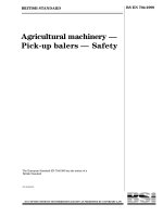
The test involves fracturing a test piece containing a
pressed notch by supporting it near its ends, and
impacting it behind the notch (see Figure 1).
The test is carried out at a specified test piece
temperature.
The test is as follows:
a) to measure the relative proportions of shear and
cleavage fracture, which are generally assessed
visually, and to derive from these either:
1) the temperature at which a specified percentage
of shear fracture has occurred (FATT); or
2) the amount of shear area produced by testing
at a specified temperature;
and/or
b) to measure absorbed energy at the specified
temperature.
9991:47201 NE
4 egaP
Lice ns e d Copy: London S outh Bank Unive rs ity, London S outh Bank Unive rs ity, Thu Mar 01 07:01:24 GMT+00:00 2007, Uncontrolle d Copy, (c) BS I
9991-90 ISB
©
Figure 1 Ð Test piece geometry and recommended flattened tube profile
I S B ) c( , y p o C d ell ort n o c nU , 7 0 0 2 0 0: 0 0+TM G 4 2: 1 0: 7 0 1 0 r aM u hT , yti sr e vi nU k n a B ht u o S n o d n oL , yti sr e vi nU k n a B ht u o S n o d n oL : y p o C d e s n e ciL
Page 5
EN 10274:1999
5 Apparatus
6 Test piece preparation
The testing machine may be a falling weight type
or a pendulum type. Other types of testing machine,
e.g. with hydraulic actuators, may be used providing it
can be demonstrated that their impact velocity and
dynamic performance conform to the requirements
of 5.2.
6.1 Test piece location
5.1
The energy available at impact to be used in the
test shall be greater than the anticipated fracture
absorption energy of the test piece (see note).
5.2
At impact the hammer velocity shall be not less
than 5 m/s and not more than 10 m/s.
NOTE To ensure regular crack propagation an available energy
of 1,5 times the absorbed energy is generally sufficient [1]. If the
absorbed energy is not measured, the minimum required impact
energy ( REQ) can be estimated from the Charpy V-notch
energy (KV) adjusted for test piece cross-sectional fracture area
using the following expression
E
EREQ = 5.6 (KV)
3 AA
DWTT
is the drop weight tear test fracture area;
is the Charpy test fracture area.
The striking edge of the hammer shall be radiused
and shall be centred on the anvil with the supports at
a span of 254 mm as shown in Figure 1. Provision shall
be made to prevent out of plane rotation of the test
piece on or after impact. The tolerances on the
machine and set up dimensions shall be in accordance
with Table 1.
5.3
Table 1 Ð Test machine dimensions and
tolerances
Measurement
S
Rs
Rh
Centre line hammer with
respect to mid-point between
anvil supports
6.2 Test piece
6.2.1 Unless otherwise specified in the product
standard the test piece may be flattened completely for
testing purposes or the central 50 mm may be left with
the original pipe curvature. In the latter case the mid
thickness at the centre of the test piece shall be in the
same plane as the mid thickness at the anvil supports
(see Figure 1).
In the case of dispute the results of tests on test pieces
with the central area unflattened shall apply.
NOTE Flattening the fracture area of the test piece may give
more conservative results than those obtained from an unflattened
test piece.
The test piece thickness shall be the full tube or
plate thickness up to and including 19 mm. For
thicknesses greater than 19 mm the test piece thickness
may be either the full tube or plate thickness or it may
be reduced to 19 mm. An alternative procedure for
testing thicker materials, reduced in thickness
to 19 mm, is given in annex A.
6.2.2
KV
where
ADWTT
AKV
Test piece location and orientation within the tube or
plate shall be as specified in the product standard.
Dimension
mm
mm
25,0
0
±1,5
15,0
Test pieces may be prepared from an oversize
flame-cut sample, however, final preparation shall be
by a cold machining process (e.g. planing, sawing, or
milling) to remove any heat affected zones. Test piece
dimensions and tolerances shall be in accordance
with Table 2.
6.2.3
Tolerance
±1,5
±1,0
±1,0
254,0
If the test piece thickness is reduced to 19 mm it shall
be agreed and documented at the time of enquiry and
order.
A temperature controlled environment shall be
provided in which the test piece can be soaked in a
suitable medium for temperature conditioning before
testing. Provision shall be made for circulation of the
medium to ensure a uniform soaking temperature.
5.4
NOTE A procedure should be developed for test temperatures
above or below room temperature to ensure that the temperature
variation between the exit from the temperature conditioning
medium and the execution of the test are within specified limits.
Table 2 Ð Test piece dimensions and
tolerances
Measurement
L
W
a
u
Rn
Dimension
mm
305,0
76,0
5,0
8
45
±1,5
50,0
The notch shall be pressed to the depth given in
Table 2 with a chisel of minimum hardness 45 HRC,
and shall have a radius of 0,02 mm 0,01 mm.
6.2.4
±
Machined notches are prohibited.
© BSI 09-1999
mm
±20,0
±1,5
±0,5
±28
0,01 to 0,04 Ð
Centre line notch with respect
to centre line of hammer
0
Lc
Tolerance
I S B ) c( , y p o C d ell ort n o c nU , 7 0 0 2 0 0: 0 0+TM G 4 2: 1 0: 7 0 1 0 r aM u hT , yti sr e vi nU k n a B ht u o S n o d n oL , yti sr e vi nU k n a B ht u o S n o d n oL : y p o C d e s n e ciL
Page 6
EN 10274:1999
The test piece shall be soaked in a suitable
medium which is at a temperature within the following
limits:
7.1
a) for test temperatures below room temperature:
+1,0 C and 10,0 C of the specified test
temperature;
8
2
8
b) for test temperatures above room temperature:
1,0 C and +10,0 C of the specified test
temperature.
2 8
The test piece shall be placed in the test machine
such that the centre line of the notch is aligned with
the centre line of the hammer. The test piece shall be
suitably restrained to prevent out of plane rotation on
or after impact.
7.3
7 Test procedure
8
Test pieces shall be separated from each other and
from the sides and bottom of the bath by a distance of
at least the test piece thickness.
When the surface of the test piece has reached the
required temperature it shall remain in the medium at
that temperature for the greater of the following times
(see note).
1) For liquid medium: 15 min or 30 s per mm
thickness.
2) For a gaseous medium: 30 min or 1 min per mm
thickness.
NOTE If evidence can be produced to show that the test piece
equilibrium temperature can be developed in a shorter time then
these holding times can be reduced.
The test piece shall be removed from the medium
and broken on the test machine, by a single blow. The
surface temperature of the test piece at the time of
testing shall be within 1,0 C of the specified test
temperature.
7.2
± 8
This condition is considered to be met if the test is
undertaken within 10 s of its removal from the soaking
medium which is itself at a temperature within 1 C of
the specified test temperature. If the test piece is out
of the medium for longer than 10 s, it shall be returned
to the bath until the requirements of 7.1 are again
fulfilled.
± 8
When appropriate the fracture absorption energy
shall be recorded. The elements of the energy
absorption shall be subject to calibration.
7.4
NOTE It has been found that the most consistent results are
obtained when using test machines with anvil support radii
of 15 mm 1 mm and hammer radius of 25 mm 1 mm as jamming
and friction are minimized under these conditions.
±
±
8 Test evaluation
8.1 Ferritic steels
The result of the test is usually expressed as a
Fracture Appearance Transition Temperature (FATT),
or as a percentage shear value at the specified
temperature defined in the product standard.
8.1.1
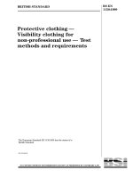
For test piece thicknesses of 19 mm or less, the
percentage shear area of the fracture surface shall be
evaluated, neglecting the fracture surface for a distance
of one test piece thickness ( ) from the root of the
notch and for a distance of one test piece thickness
from the side opposite the notch. For test piece
thicknesses greater than 19 mm, the neglected regions
shall be 19 mm. The shaded area in Figure 2 illustrates
that portion of the fracture surface to be considered in
the evaluation of the percentage shear area.
8.1.2
T
Methods for calculating the percentage shear area for
ferritic steels are given in annex B.
Excessive plastic deformation at the impact point may
occur in very tough materials over 19 mm thick which
leads to conservative results. An alternative method for
assessing the FATT of ferritic steels having thicknesses
greater than 19 mm is given in annex A which can also
be used when the impact energy of the test machine is
limited.
Figure 2 Ð Fracture surface included in percentage shear area
determination
© BSI 09-1999
I S B ) c( , y p o C d ell ort n o c nU , 7 0 0 2 0 0: 0 0+TM G 4 2: 1 0: 7 0 1 0 r aM u hT , yti sr e vi nU k n a B ht u o S n o d n oL , yti sr e vi nU k n a B ht u o S n o d n oL : y p o C d e s n e ciL
Page 7
EN 10274:1999
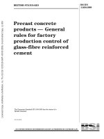
The fracture shall be assessed when viewed
perpendicularly to the surface. If a fracture surface
exhibits areas having an arrowhead form, these areas
shall be classed as cleavage (see Figure 3).
8.1.3
Occasionally test pieces exhibiting the fracture
appearance shown in Figure 4 will be encountered.
These fractures have intermittent regions of shear and
cleavage fracture. The individual areas of cleavage
fracture shall be summed.
Cleavage in separations not included in shear area
rating are shown in Figure 5.
NOTE Shear areas may contain areas of apparent separation
which can be ignored.
8.2 Other materials
The result of the test is generally expressed as the
fracture absorption energy.
Figure 5 Ð Cleavage in separations not
included in shear area rating
9 Test report
C denotes the cleavage regions
Figure 3 Ð Appearance of arrowhead
cleavage fracture
The test report shall include at least the following
information:
a) reference to this European Standard i.e. EN 10274;
b) identification of the test piece; e.g. cast No./
tube No./identification No.;
c) material specification if known;
d) dimensions of the plate or tube;
e) test piece thickness;
f) impact energy used in the test or the mass and
height of drop of the hammer;
g) whether the test piece has been flattened;
C denotes the cleavage regions
Figure 4 Ð Alternate shear±cleavage
fracture appearance
h) the percentage shear area and test temperature of
each test piece when appropriate;
i) the fracture appearance transition temperature
corresponding to a specified percentage shear area
when appropriate;
j) fracture absorption energy when appropriate.
© BSI 09-1999
I S B ) c( , y p o C d ell ort n o c nU , 7 0 0 2 0 0: 0 0+TM G 4 2: 1 0: 7 0 1 0 r aM u hT , yti sr e vi nU k n a B ht u o S n o d n oL , yti sr e vi nU k n a B ht u o S n o d n oL : y p o C d e s n e ciL
Page 8
EN 10274:1999
For shear areas between 45 % and 100 % of the
fracture surface on test piece thicknesses of 19 mm or
less the percentage shear area may be calculated from
the formula:
x) T ± (3/4) AB] 3 100
When this procedure is adopted, it is necessary for test
% shear area = [(W ± a ± 2(W
pieces with thicknesses greater than 19 mm to be
± a ± 2x)T
reduced in thickness to 19 mm minimum by machining
one or both surfaces. They should be tested and
where
assessed as described in clauses 7 and 8.
A is the width of the cleavage fracture at the
For ferritic steels #40 mm thick the test temperature
ªone Tº line beneath the notch (mm);
should be reduced by the amount given in Table A.1.
B is the length of the cleavage fracture in
NOTE For ferritic materials greater than 40 mm thick and for
between the ªone Tº lines (mm);
other materials the procedure to be used should be agreed
between the purchaser and manufacturer at the time of enquiry
T is the test piece thickness (mm);
and order.
W is the width of the test piece (mm);
Table A.1 Ð Reduction in test temperature
a is the depth of the pressed notch (mm);
Plate or tube wall thickness
Temperature reduction
x is the test piece thickness #19 mm
mm
8C
(x = 19 for thicknesses > 19 mm).
>19 #22
5,5
Annex C (informative)
>22 #29
11,0
Bibliography
>29 #40
17,0
[1] Fallgewichtversuch nach Battelle,
Stahl-Eisen-PruÈfblatt 1326:1983.
Annex B (informative)
Annex A (informative)
Alternative procedure for testing thick
material
B.2
Method for calculating the percentage
shear area for ferritic materials
The percentage shear area of the fracture surface
should be determined by one of the following methods.
Ð Measure the shear area of the fracture with a
planimeter on photograph or optical projection of
the fracture surface.
Ð Compare the fracture surface with a set of
reference specimens. The percent shear area of the
reference specimens should have been evaluated
with a planimeter; the thickness of the reference
specimen should be identical to that of the evaluated
specimen ±3 mm.
Ð Follow the procedure described in B.2.
Ð Use any other procedure that can be shown to
produce results equivalent to those obtained from
one of the three methods above.
B.1
© BSI 09-1999
knalb
Lice ns e d Copy: London S outh Bank Unive rs ity, London S outh Bank Unive rs ity, Thu Mar 01 07:01:24 GMT+00:00 2007, Uncontrolle d Copy, (c) BS I
I S B ) c( , y p o C d ell ort n o c nU , 7 0 0 2 0 0: 0 0+TM G 4 2: 1 0: 7 0 1 0 r aM u hT , yti sr e vi nU k n a B ht u o S n o d n oL , yti sr e vi nU k n a B ht u o S n o d n oL : y p o C d e s n e ciL
BS EN
10274:1999
BSI
389 Chiswick High Road
London
W4 4AL
|
|
|
|
|
|
|
|
|
|
|
|
|
|
|
|
|
|
|
|
|
|
|
|
|
|
|
|
|
|
|
|
|
|
|
|
|
|
|
|
|
|
|
|
|
|
|
|
|
|
|
|
|
|
|
|
|
|
|
|
|
|
|
|
|
|
|
|
|
|
|
|
|
|
|
|
|
|
|
|
|
|
|
|
|
|
|
|
|
|
|
|
|
|
|
|
|
|
|
|
|
|
|
|
|
|
|
|
|
|
|
|
|
|
|
|
|
|
|
|
|
|
|
|
|
|
|
BSI Ð British Standards Institution
BSI is the independent national body responsible for preparing British Standards. It
presents the UK view on standards in Europe and at the international level. It is
incorporated by Royal Charter.
Revisions
British Standards are updated by amendment or revision. Users of British Standards
should make sure that they possess the latest amendments or editions.
It is the constant aim of BSI to improve the quality of our products and services. We
would be grateful if anyone finding an inaccuracy or ambiguity while using this
British Standard would inform the Secretary of the technical committee responsible,
the identity of which can be found on the inside front cover. Tel: 020 8996 9000.
Fax: 020 8996 7400.
BSI offers members an individual updating service called PLUS which ensures that
subscribers automatically receive the latest editions of standards.
Buying standards
Orders for all BSI, international and foreign standards publications should be
addressed to Customer Services. Tel: 020 8996 9001. Fax: 020 8996 7001.
In response to orders for international standards, it is BSI policy to supply the BSI
implementation of those that have been published as British Standards, unless
otherwise requested.
Information on standards
BSI provides a wide range of information on national, European and international
standards through its Library and its Technical Help to Exporters Service. Various
BSI electronic information services are also available which give details on all its
products and services. Contact the Information Centre. Tel: 020 8996 7111.
Fax: 020 8996 7048.
Subscribing members of BSI are kept up to date with standards developments and
receive substantial discounts on the purchase price of standards. For details of
these and other benefits contact Membership Administration. Tel: 020 8996 7002.
Fax: 020 8996 7001.
Copyright
Copyright subsists in all BSI publications. BSI also holds the copyright, in the UK, of
the publications of the international standardization bodies. Except as permitted
under the Copyright, Designs and Patents Act 1988 no extract may be reproduced,
stored in a retrieval system or transmitted in any form or by any means ± electronic,
photocopying, recording or otherwise ± without prior written permission from BSI.
This does not preclude the free use, in the course of implementing the standard, of
necessary details such as symbols, and size, type or grade designations. If these
details are to be used for any other purpose than implementation then the prior
written permission of BSI must be obtained.
If permission is granted, the terms may include royalty payments or a licensing
agreement. Details and advice can be obtained from the Copyright Manager.
Tel: 020 8996 7070.