Bsi bs en 10275 1999
Bạn đang xem bản rút gọn của tài liệu. Xem và tải ngay bản đầy đủ của tài liệu tại đây (339.68 KB, 10 trang )
BRITISH STANDARD
Metallic materials Ð
Tube ring hydraulic
pressure test
The European Standard EN 10275:1999 has the status of a
British Standard
ICS 77.040.10
NO COPYING WITHOUT BSI PERMISSION EXCEPT AS PERMITTED BY COPYRIGHT LAW
|
|
|
|
|
|
|
|
|
|
|
|
|
|
|
|
|
|
|
|
|
|
|
|
|
|
|
|
|
|
|
|
|
|
|
|
|
|
|
|
|
|
|
|
|
|
|
|
|
|
|
|
|
|
|
|
|
|
|
|
|
|
|
|
|
|
|
|
|
|
|
|
|
|
|
|
|
|
|
|
|
|
|
|
|
|
|
|
|
|
|
|
|
|
|
|
|
|
|
|
|
|
|
|
|
|
|
|
|
|
|
|
|
|
|
|
|
|
|
|
|
|
|
|
|
|
|
|
|
BS EN
10275:1999
BS EN 10275:1999
National foreword
This British Standard is the English language version of EN 10275:1999.
The UK participation in its preparation was entrusted by Technical Committee
ISE/NFE/4, Mechanical testing of metals, to Subcommittee ISE/NFE/4/2, Ductility
tests, which has the responsibility to:
Ð aid enquirers to understand the text;
Ð present to the responsible European committee any enquiries on the
interpretation, or proposals for change, and keep the UK interests informed;
Ð monitor related international and European developments and promulgate
them in the UK.
A list of organizations represented on this subcommittee can be obtained on request
to its secretary.
Cross-references
The British Standards which implement international or European publications
referred to in this document may be found in the BSI Standards Catalogue under the
section entitled ªInternational Standards Correspondence Indexº, or by using the
ªFindº facility of the BSI Standards Electronic Catalogue.
A British Standard does not purport to include all the necessary provisions of a
contract. Users of British Standards are responsible for their correct application.
Compliance with a British Standard does not of itself confer immunity
from legal obligations.
Summary of pages
This document comprises a front cover, an inside front cover, the EN title page,
pages 2 to 7 and a back cover.
The BSI copyright notice displayed throughout this document indicates when the
document was last issued.
This British Standard, having
Amendments issued since publication
been prepared under the
direction of the Engineering
Sector Committee, was published
under the authority of the
Standards Committee and comes
into effect on 15 September 1999
©
BSI 09-1999
ISBN 0 580 32637 3
Amd. No.
Date
Comments
EN 10275
EUROPEAN STANDARD
 ENNE
NORME EUROPE
È ISCHE NORM
EUROPA
May 1999
ICS 77.040.10
English version
Metallic materials Ð Tube ring hydraulic pressure test
Mate
 riaux me
 talliques РEssai d'expansion
Metallische Werkstoffe Ð Hydraulischer
hydraulique sur anneau tubulaire
Ringaufweitversuch
This European Standard was approved by CEN on 16 April 1999.
CEN members are bound to comply with the CEN/CENELEC Internal Regulations
which
stipulate
national
the conditions for giving
standard
without
any
this
alteration.
European
Up-to-date
Standard
lists
the
and
status
of a
bibliographical
references concerning such national standards may be obtained on application to
the Central Secretariat or to any CEN member.
This European Standard exists in three official versions (English, French, German).
A version in any other language made by translation under the responsibility of a
CEN member into its own language and notified to the Central Secretariat has the
same status as the official versions.
CEN
members
Republic,
are
Denmark,
Luxembourg,
the
national
Finland,
Netherlands,
standards
France,
Norway,
bodies
Germany,
Portugal,
of
Austria,
Greece,
Spain,
Belgium,
Iceland,
Sweden,
Czech
Ireland,
Switzerland
Italy,
and
United Kingdom.
CEN
European Committee for Standardization
Comite
 Europe
 en de Normalisation
Europa
È isches Komitee fu
È r Normung
Central Secretariat: rue de Stassart 36, B-1050 Brussels
©
1999 CEN All rights of exploitation in any form and by any means reserved worldwide for CEN national
Members.
Ref. No. EN 10275:1999 E
Page 2
EN 10275:1999
Foreword
This European Standard has been prepared by
Technical Committee ECISS/TC 29, Steel tubes and
fittings for steel tubes, the Secretariat of which is held
by UNI.
Contents
Page
Foreword
2
1
Scope
3
This European Standard shall be given the status of a
national standard, either by publication of an identical
text or by endorsement, at the latest by
November 1999, and conflicting national standards
shall be withdrawn at the latest by November 1999.
2
Symbols
3
3
Principle
3
4
Apparatus
3
5
Test ring
3
This European Standard has been prepared under a
mandate given to CEN by the European Commission
and the European Free Trade Association. This
European Standard is considered to be a supporting
standard to those application and product standards
which in themselves support an essential safety
requirement of a New Approach Directive and which
make reference to this European Standard.
6
Test procedure
5
7
Hoop strength evaluation
6
8
Test report
6
Annex A (informative) Proof and reduced
section testing
7
According to the CEN/CENELEC Internal Regulations,
the national standards organizations of the following
countries are bound to implement this European
Standard: Austria, Belgium, Czech Republic, Denmark,
Finland, France, Germany, Greece, Iceland, Ireland,
Italy, Luxembourg, Netherlands, Norway, Portugal,
Spain, Sweden, Switzerland and the United Kingdom.
© BSI 09-1999
Page 3
EN 10275:1999
4 Apparatus
1 Scope
This European Standard specifies the ring hydraulic
pressure test for metallic tubes. It is generally applied
to tubes with an outside diameter generally greater
than 120 mm and outside diameter to thickness ratio
not less than 20.
The objective of this test is to ascertain the value of
the hoop stress required to produce a specified total
circumferential (hoop) strain.
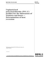
4.1 The testing machine shall be capable of allowing
the test ring to expand freely without imposing any
end restraint. This shall be achieved by leaving a small
gap between the test piece and the top platen.
Pressure loss during testing shall be prevented by the
use of a flexible seal.
NOTE A typical testing machine is shown schematically
in Figure 2.
To reduce friction between the test piece, platens
and inner die to a minimum, the platens shall be
parallel and have a fine turned or ground finish. Prior
to each test, friction at the contact surfaces shall be
further minimized either by the use of a lubricant
e.g. graphited grease or by the use of PTFE
(polytetrafluorethylene) sheet. The platens shall be
inspected regularly and any ridges that develop shall
be removed.
4.2
2 Symbols
Symbols and corresponding designations are given
in Table 1.
Table 1 Ð Symbols and designations
Symbol
T
D
L
p
x
Rtx
Unit
Designation
mm
Measured tube test ring thickness
mm
Measured outside diameter of the
tube test ring
mm
Length of tube test ring
Stress shall be applied to the test ring by means
of a pressurized fluid. Provision shall be made to
remove any air in the system through a bleed line.
N/mm2
Hydrostatic pressure to produce
the specified total strain
5 Test ring
Specified total strain
5.1 Shape and position
N/mm2
Hoop strength at the specified
total strain
3 Principle
The test involves the unrestrained expansion of the
test ring between two platens, under internal hydraulic
pressure; the outer circumference of the tube is the
effective test piece gauge length.
The test is carried out on a test piece (see Figure 1)
removed from a welded or seamless tube of thickness
up to a limit dependent upon the capacity of the
machine and the strength of the tube. Where the
hydraulic pressure required to produce the specified
circumferential strain exceeds the capacity of the test
machine modified tests may be carried out as
described in annex A.
The test is specified when a measure of the hoop
strength is required which is not influenced by cold
forming and residual stress introduced when flattening
a standard tensile test piece. The standard tensile test
is necessary, however, when tensile strength and
elongation measurements are required.
4.3
Prior to separation from the main body of the
tube the test ring shall be marked with a unique
identification.
5.1.1
The test ring may be prepared from an oversize
flame cut sample. Final preparation shall be by a cold
machining process to ensure removal of any heat
affected zones. The machined edges shall have a fine
turned or ground finish and be free from burrs.
5.1.2
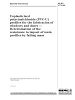
The dimensions and tolerances for the test piece
are given in Figure 1. The machined edges shall be
parallel and normal to the axis of the tube to
within 0,15 mm measured across the diameter.
5.1.3
5.2 Determination of dimensions
5.2.1 The outside diameter of the test ring shall be
calculated from measurement of the tube
circumference, e.g. using a flexible steel tape. The
maximum tolerance on the accuracy of this
measurement shall be 1 mm.
±
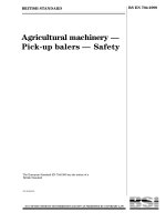
The wall thickness shall be determined by
calculating the mean of eight measurements taken at
approximately 458 intervals around the test piece,
excluding the weld region of welded tubes
(see Figure 3). The measuring device shall be capable
of measuring thickness with an accuracy of better
than 0,025 mm.
5.2.2
All tube diameter and thickness measurements
of the test ring shall be fully documented.
5.2.3
© BSI 09-1999
Page 4
EN 10275:1999
1)
Tolerance on
L ±0,25 mm.
L is commonly taken as 76 mm.
NOTE
Remove all sharp edges and protect machined surfaces.
Figure 1 Ð Test ring dimensions and tolerances
Figure 2 Ð Schematic diagram of testing machine (with insalled test ring)
© BSI 09-1999
Page 5
EN 10275:1999
The equipment for measuring the increase in
circumference shall be wrapped around the test ring
before application of the internal pressure.
6.4 The tolerance for the measurement of internal
pressure shall be within ±1 %. Accuracy of the pressure
measurement device shall be verified, e.g. by
comparison with dead weight test equipment, at the
commencement of a sequence of testing and then once
every 200 tests, and not less than once per year during
the testing period.
6.5 The rate of strain shall not exceed 0,2 % per
minute.
6.6 The pressure and circumferential extension output
signals shall be recorded, for example on a X±Y plotter,
and related to the test piece identity.
6.3
6 Test procedure
The test procedure consists of applying pressure
and measuring circumferential extension.
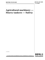
6.2 Circumferential extension of the test ring shall be
measured during pressurization as follows. The
equipment for measuring the change of circumference,
e.g. steel tape or roller chain extensometer shall be
wrapped around the test ring perimeter at the
mid-point and crossing at the weld.
6.1
NOTE An example of the use of a steel tape is shown
in Figure 4.
When a steel tape is used friction shall be minimized
by coating both the tape and test ring circumference
with a suitable lubricant. Change in circumference
shall be measured by a suitable mechanical or
electrical device having an accuracy of ±0,25 mm.
Figure 3 Ð Wall thickness measurement positions
© BSI 09-1999
Page 6
EN 10275:1999
NOTE The separation between the two parallel portions of the measuring device shall be between 1,5 mm
and 3,0 mm.
Figure 4 Ð Measuring device position for extension measurement
7 Hoop strength evaluation
8 Test report
A typical test pressure±circumferential extension
record is shown in Figure 5.
The test report shall contain at least the following
information:
7.1
The pressure p corresponding to the specified
total strain shall be determined from the test record.
7.2
$
For tubes where D/T
20 the hoop strength at
the specified total strain shall be calculated from the
formula:
7.3
Rtx =
a) reference to this European Standard i.e. EN 10275;
b) identification of test ring, e.g. cast No./tube No.
/identification No.;
c) material specification, if known;
d) diameter and wall thickness of the tube;
pD
e) length of the tube test ring;
2T
f) calculated hoop strength at specified total strain;
NOTE 1 For tubes with D/T < 20 the hoop strength calculated
from this formula becomes increasingly inaccurate and
quantitative results should be used with caution. Factors such as
strain hardening could have a significant effect on the validity of
the calculated strength.
g) reference to an alternative test method used,
when appropriate (see annex A).
NOTE 2 The specified total strain is calculated from the
circumferential extension divided by the original test ring
circumference.
© BSI 09-1999
Page 7
EN 10275:1999
Figure 5 Ð Typical pressure/extension test record
Annex A (informative)
Proof and reduced section testing
A.1 Proof testing
This method may be used where the stress necessary
to produce the specified circumferential extension has
not been achieved but where the stress in the test ring
exceeds the specified minimum hoop strength
requirement. In this case the percentage
circumferential expansion achieved shall be quoted in
the report.
A.2 Reduced section testing
This method enables the stress corresponding to the
specified circumferential extension to be achieved by a
reduction in the test ring thickness. This reduction can
be effected by machining the inside and/or outside
diameter. To ensure that the full thickness is
represented two or possibly three tests should be
carried out after machining i) inside, ii) outside
and iii) both diameters. Details of all test piece
locations and dimensions relative to the full thickness
ring section will be included in the report.
© BSI 09-1999
BS EN
10275:1999
BSI
389 Chiswick High Road
London
W4 4AL
|
|
|
|
|
|
|
|
|
|
|
|
|
|
|
|
|
|
|
|
|
|
|
|
|
|
|
|
|
|
|
|
|
|
|
|
|
|
|
|
|
|
|
|
|
|
|
|
|
|
|
|
|
|
|
|
|
|
|
|
|
|
|
|
|
|
|
|
|
|
|
|
|
|
|
|
|
|
|
|
|
|
|
|
|
|
|
|
|
|
|
|
|
|
|
|
|
|
|
|
|
|
|
|
|
|
|
|
|
|
|
|
|
|
|
|
|
|
|
|
|
|
|
|
|
|
|
BSI Ð British Standards Institution
BSI is the independent national body responsible for preparing British Standards. It
presents the UK view on standards in Europe and at the international level. It is
incorporated by Royal Charter.
Revisions
British Standards are updated by amendment or revision. Users of British Standards
should make sure that they possess the latest amendments or editions.
It is the constant aim of BSI to improve the quality of our products and services. We
would be grateful if anyone finding an inaccuracy or ambiguity while using this
British Standard would inform the Secretary of the technical committee responsible,
the identity of which can be found on the inside front cover. Tel: 020 8996 9000.
Fax: 020 8996 7400.
BSI offers members an individual updating service called PLUS which ensures that
subscribers automatically receive the latest editions of standards.
Buying standards
Orders for all BSI, international and foreign standards publications should be
addressed to Customer Services. Tel: 020 8996 9001. Fax: 020 8996 7001.
In response to orders for international standards, it is BSI policy to supply the BSI
implementation of those that have been published as British Standards, unless
otherwise requested.
Information on standards
BSI provides a wide range of information on national, European and international
standards through its Library and its Technical Help to Exporters Service. Various
BSI electronic information services are also available which give details on all its
products and services. Contact the Information Centre. Tel: 020 8996 7111.
Fax: 020 8996 7048.
Subscribing members of BSI are kept up to date with standards developments and
receive substantial discounts on the purchase price of standards. For details of
these and other benefits contact Membership Administration. Tel: 020 8996 7002.
Fax: 020 8996 7001.
Copyright
Copyright subsists in all BSI publications. BSI also holds the copyright, in the UK, of
the publications of the international standardization bodies. Except as permitted
under the Copyright, Designs and Patents Act 1988 no extract may be reproduced,
stored in a retrieval system or transmitted in any form or by any means ± electronic,
photocopying, recording or otherwise ± without prior written permission from BSI.
This does not preclude the free use, in the course of implementing the standard, of
necessary details such as symbols, and size, type or grade designations. If these
details are to be used for any other purpose than implementation then the prior
written permission of BSI must be obtained.
If permission is granted, the terms may include royalty payments or a licensing
agreement. Details and advice can be obtained from the Copyright Manager.
Tel: 020 8996 7070.