Bsi bs en 12213 1998
Bạn đang xem bản rút gọn của tài liệu. Xem và tải ngay bản đầy đủ của tài liệu tại đây (682.85 KB, 14 trang )
BRITISH STANDARD
|
|
|
|
|
BS EN
12213:1999
|
|
|
|
|
|
|
|
|
Cryogenic vessels Ð Methods
for performance evaluation of
thermal insulation
|
|
|
|
|
|
|
|
|
|
|
|
|
|
|
|
|
|
|
|
|
|
|
|
|
|
|
|
|
|
|
|
|
|
|
|
|
|
|
|
|
|
|
|
|
|
|
|
|
|
|
|
|
|
|
|
|
|
|
|
|
|
|
|
|
|
|
|
|
|
|
|
|
|
|
|
|
|
|
|
|
|
|
|
|
|
|
|
|
|
|
|
The
E uropean Standard E N 1 2 2 1 3: 1 998
has
the
status
of a
|
|
British Standard
|
|
|
|
|
|
|
|
IC S
2 3. 02 0. 30
|
|
|
|
|
|
|
|
NO COPYING WITHOUT BSI PERMISSION EXCEPT AS PERMITTED BY COPYRIGHT LAW
|
|
|
|
|
Confirmed
March 2008
BS EN 12213:1999
National foreword
This British Standard is the English language version of EN 12213:1998.
The UK participation in its preparation was entrusted to Technical Committee
PVE/18, Cryogenic vessels, which has the responsibility to:
Ð aid enquirers to understand the text;
Ð present to the responsible European committee any enquiries on the
interpretation, or proposals for change, and keep the UK interests informed;
Ð monitor related international and European developments and promulgate
them in the UK.
A list of organizations represented on this committee can be obtained on request to
its secretary.
Cross-references
The British Standards which implement international or European publications
referred to in this document may be found in the BSI Standards Catalogue under the
section entitled ªInternational Standards Correspondence Indexº, or by using the
ªFindº facility of the BSI Standards Electronic Catalogue.
A British Standard does not purport to include all the necessary provisions of a
contract. Users of British Standards are responsible for their correct application.
Compliance with a British Standard does not of itself confer immunity
from legal obligations.
Summary of pages
This document comprises a front cover, an inside front cover, the EN title page,
pages 2 to 10, an inside back cover and a back cover.
This British Standard, having
been prepared under the
direction of the Engineering
Sector Committee, was published
under the authority of the
Standards Committee and comes
into effect on 15 April 1999
BSI 04-1999
ISBN 0 580 30605 4
Amendments issued since publication
Amd. No.
Date
Text affected
EN 12213
EUROPEAN STANDARD
NORME EUROPÊENNE
EUROPẰISCHE NORM
November 1998
ICS 27.200
Descriptors: pressure vessels, cryogeny, definitions, tests, estimation, characteristics, thermal insulation, testing conditions
English version
Cryogenic vessels Ð Methods for performance evaluation of
thermal insulation
ReÂcipients cryogeÂniques Ð MeÂthodes d'eÂvaluation
de la performance de l'isolation thermique
Kryo-BehaÈlter Ð Verfahren zur Bewertung des
WaÈrmedaÈmmvermoÈgens
This European Standard was approved by CEN on 4 September 1998.
CEN members are bound to comply with the CEN/CENELEC Internal Regulations
which stipulate the conditions for giving this European Standard the status of a
national standard without any alteration. Up-to-date lists and bibliographical
references concering such national standards may be obtained on application to the
Central Secretariat or to any CEN member.
This European Standard exists in three official versions (English, French, German).
A version in any other language made by translation under the responsibility of a
CEN member into its own language and notified to the Central Secretariat has the
same status as the official versions.
CEN members are the national standards bodies of Austria, Belgium, Czech
Republic, Denmark, Finland, France, Germany, Greece, Iceland, Ireland, Italy,
Luxembourg, Netherlands, Norway, Portugal, Spain, Sweden, Switzerland and
United Kingdom.
CEN
European Committee for Standardization
Comite EuropeÂen de Normalisation
EuropaÈisches Komitee fuÈr Normung
Central Secretariat: rue de Stassart 36, B-1050 Brussels
1998 CEN All rights of exploitation in any form and by any means reserved worldwide for CEN national
Members.
Ref. No. EN 12213:1998 E
Page 2
EN 12213:1998
Foreword
This European Standard has been prepared by
Technical Committee CEN/TC 268, Cryogenic vessels,
the Secretariat of which is held by AFNOR.
This European Standard shall be given the status of a
national standard, either by publication of an indentical
text or by endorsement, at the latest by May 1999, and
conflicting national standards shall be withdrawn at
the latest by May 1999.
This European Standard has been prepared under a
mandate given to CEN by the European Commission
and the European Free Trade Association. This
European Standard is considered to be a supporting
standard to those application and product standards
which in themselves support an essential safety
requirement of a New Approach Directive and which
make reference to this European Standard.
According to the CEN/CENELEC Internal Regulations,
the national standards organizations of the following
countries are bound to implement this European
Standard: Austria, Belgium, Czech Republic, Denmark,
Finland, France, Germany, Greece, Iceland, Ireland,
Italy, Luxembourg, Netherlands, Norway, Portugal,
Spain, Sweden, Switzerland and the United Kingdom.
Contents
Foreword
Introduction
1
Scope
2
Definitions
3
General conditions for all methods
4
Measuring the heat leak by the loss of
product method
4.1 General
4.2 Test procedure
4.3 Determination of the heat leak in units of
energy per unit time
4.4 Determination of the heat leak as a
percentage of product lost per 24 h
5
Determination of the holding time
(open system) in days from heat leak data
6
Holding times for closed systems
6.1 Determination of the the equilibrium
holding time from heat leak data
6.2 Determination of the optimum equilibrium
holding time from heat leak data
6.3 Static experimental holding time
7
Test report
8
Bibliography
Annex A (normative) Conversion of measured
volumetric gaseous flow to mass flow
Annex B (normative) Correction of measured
mass flow rate with regard to deviation from
reference conditions
Annex C (normative) Equivalent loss
determination, for product other than the test
product
Page
2
3
3
3
3
5
5
5
5
5
6
6
6
6
7
7
7
7
8
10
BSI 04-1999
Page 3
EN 12213:1998
Introduction
Traditionally in Europe, there have been different ways
of defining the insulation performance. A requirement
exists therefore to harmonize such methods of
evaluating insulation performance for different
cryogenic vessels.
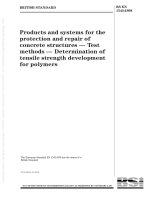
To aid the understanding of this standard, see the logic
diagram in Figure 1.
1 Scope
This standard defines a pratical method for
determining the heat leak performance of cryogenic
vessels. The methods include measurement on both
open and closed systems.
This standard neither specifies the requirement levels
for insulation performance nor when the methodology
defined is applied. These requirements may be defined
in design or operational standards/regulations.
2 Definitions
For the purpose of this standard, the following
definitions apply.
2.1
open system
during test, a system is considered open when it is
kept at a constant pressure (e.g. atmospheric pressure)
and when the gas produced by the evaporation of the
test fluid is continuously released to the atmosphere
2.2
closed system
during test, a system is considered closed when the
mass of the contents is kept constant with no input or
output of product
2.3
heat leak performance
the quantity of heat transferred per unit time from the
ambient air to the contents of the inner vessel
NOTE In an open system the heat leak causes a loss of product.
In a closed system it causes a rise in pressure.
2.4
holding time, open system
the time expected to elapse from initial filling level
until the vessel is empty (no more liquid), calculated
from heat leak data
2.5
holding time, closed system
the time elapsed from establishing the initial filling
condition until the pressure has risen, due to heat leak,
to the set pressure of the pressure limiting device
NOTE A pressure limiting device is either a safety valve or a
rupture disc or a back pressure regulator or any other device
installed to limit the system pressure under normal operating
conditions.
BSI 04-1999
2.5.1
equilibrium holding time
the holding time calculated from a specified heat leak
assuming that liquid and vapour are constantly in
equilibrium
2.5.2
optimum equilibrium holding time
the equilibrium holding time calculated from heat leak
data for a vessel when filled with the quantity of
product giving the longest holding time
2.5.3
static experimental holding time
a) when the critical pressure is greater than the set
pressure of the limiting device, the holding time of a
closed system measured on a stationary vessel filled
with a quantity of product which is calculated to fill
the tank to its gross volume without hydrostatic
deformation, with saturated liquid at the set pressure
of the pressure limiting device
b) when the critical pressure is less than the set
pressure of the limiting device, the holding time of a
closed system measured on a stationary vessel
initially filled with the least mass of the specified
product determined as follows:
Ð the maximum allowable mass of filling;
or
Ð the quantity of product which fills the vessel to
its gross volume, without hydrostatic deformation,
with liquid saturated to 99 % of its gross volume at
the critical pressure.
3 General conditions for all methods
The measurements described in this standard shall be
carried out under the following conditions.
3.1 The cryogenic fluid used for testing shall be
chosen by the manufacturer. Liquid nitrogen should
normally be used except in cases where the vessel to
be tested is designed for a specific cryogenic fluid.
3.2 The liquid and gaseous phases shall be in
equilibrium at the beginning of a test. When a test is
carried out at a higher pressure than one bar gauge, it
is important that the liquid equilibrium pressure is not
lower than this test pressure.
3.3 The test environment shall be stable and constant
during the test. It shall be as close as possible to the
following reference conditions:
Ð ambient temperature: 15 8C;
Ð atmospheric pressure: 1 013 mbar.
For products except carbon dioxide and nitrous oxide:
Ð vessel reference pressure: 1 013 mbar.
For carbon dioxide and nitrous oxide:
Ð vessel reference pressure: 15 bar (gauge).
Figure 1 Ð Logic diagram
Page 4
EN 12213:1998
BSI 04-1999
Page 5
EN 12213:1998
3.4 The vessel and its contents shall have reached a
stable temperature before the beginning of the
measuring period. Equilibrium conditions are obtained
after a period of stabilization, the duration of which
depends on the size of the vessel and the type and
configuration of the insulation.
3.5 All accessories of the vessel which can have an
influence on the result of the measurement shall be
clearly defined and specified in the report.
3.6 All instrumentation used shall be periodically
verified by calibration.
3.7 It is not necessary to use the method defined in
this standard to evaluate the insulation performance
resulting from small modifications (this evaluation can
be obtained by simple extrapolation).
4 Measuring the heat leak by the loss of
product method
4.1 General
There are two methods of measuring the heat leak:
Ð by direct measurement of loss of mass;
Ð by indirect measurement of loss of mass by
measuring the gaseous volumetric discharge rate.
The filling level shall be (50 ± 10) % of the maximum
filling level at the start of measurement, unless
otherwise stated.
The ambient temperature and the operating pressure at
the top of the vessel shall be recorded throughout the
test so as to be used for correction purposes. The
temperature sensor(s) shall be placed in the immediate
proximity of the test object, but sited such that they
are unaffected directly by cold gas discharged from the
vents.
The minimum measurement duration shall be 24 h after
stable conditions have been reached.
During the test precautions shall be taken to avoid
agitation of the liquid.
When measuring the rate of discharge of gas escaping
from the vessel by a flow meter, it is essential that the
entire gas flow passes through the meter. The gas flow
rate shall be determined as a mass flow rate either by:
Ð using a mass flow meter;
or
Ð using a volumetric flow meter. An appropriate
method is shown in annex A.
4.2 Test procedure
The test procedure shall be as follows:
step 1 : vessel precooling;
step 2 : stabilization;
step 3 : adjustment of the filling to the intended
starting level (e.g. 50 % ± 10 %);
step 4 : connection of instrumentation
(e.g. gas flow meter);
BSI 04-1999
step 5 : second stabilization period;
step 6 : determination of mass of contents of vessel
at start of measuring period;
step 7 : a sufficient number of readings shall be taken
to establish an acceptable thermal equilibrium
before the start of the measuring period;
step 8 : measuring period shall be at least 24 h;
step 9 : determination of the loss of product in mass
units (when gaseous flow is measured) in
accordance with annex A;
step 10 : reduction to reference conditions in
accordance with annex B.
4.3 Determination of the heat leak in units of
energy per unit time
The rate of product loss (kg/s) during the
measurement period, corrected to the reference
conditions in accordance with annexes A and B, shall
be converted to an equivalent heat leak, Q, by
multiplying it by the latent heat of evaporation (J/kg)
of the product at the reference conditions.
To calculate the heat leak with a product other than
the test product, compensation using linear
extrapolation in accordance with annex C may be
applied but only if the difference between the boiling
temperature of these products at the reference
conditions does not exceed 20 8C.
4.4 Determination of the heat leak as a
percentage of product lost per 24 h
Based on the result obtained in accordance with 4.3 ,
the heat leak as a percentage of product lost per 24 h
is calculated as follows:
a) correct the measured heat leak to reference
condition for the test product by linear extrapolation
as specified in 4.3 ;
b) calculate the equivalent loss of the test product
per day in accordance with the formula:
Q´ 100 %
L = 86 h400´
´F
where
F is the maximum allowable filling mass of the test
product (kg);
L is the equivalent loss of product in % of F per
day;
Q is the heat leak (W);
h is the latent heat of vaporisation (J/kg) at the
vessel reference pressure (see 3.3 );
86 400 is the number of seconds per day.
All product related data shall be taken at correct
reference conditions for the specified product. Annex C
may be used to determine the equivalent loss of
product in % of full tank content per day, for product
other than the test product.
Page 6
EN 12213:1998
5 Determination of the holding time
(open system) in days from heat leak
data
100
The holding time in days is equal to
L for the
specified product, which is equivalent to 100 times the
reciprocal of the loss of product per 24 h in percent
(as determined in 4.4).
6 Holding times for closed systems
6.1 Determination of the equilibrium holding
time from heat leak data
The following general rules shall be applied:
Ð the system is in thermal equilibrium, i.e. the liquid
and gas phases are saturated and at a temperature
corresponding to the saturation pressure at all times.
The calculation process shall incorporate correctly
the temperature and pressure dependence of the
thermodynamic properties. The data source used for
calculations shall be identified and the actual value
shall be shown in the calculation. Thermodynamic
data from reference [1] of clause 8 may be used. The
influence of phase change in the system has to be
accounted for in a proper manner;
Ð the thermal mass of the vessel shall be neglected
in the calculation, which results in shorter holding
times;
Ð for degree of filling above the optimum, the end
of holding time period shall be defined as when the
liquid phase fills the vessel to its gross volume;
Ð heat leak data may be used corrected in
accordance with annex C when different products
are concerned.
6.2 Determination of the optimum equilibrium
holding time from heat leak data
The optimum equilibrium holding time for a specific
product shall be calculated from heat leak data as
follows:
a) correct the heat leak, Q, measured in accordance
with clause 4, to reference conditions for the
specified product by linear extrapolation (see annex C);
b) determine the reference quantity of the specified
product on the basis of either:
1) when the critical pressure is greater than the
pressure of the pressure limiting device
the quantity of product which fills the vessel to its
gross volume with saturated liquid at the set
pressure of the pressure limiting device;
or
2) when the critical pressure is less than the
pressure of the pressure limiting device
the quantity of product which fills the vessel to its
gross volume with liquid saturated at 99 % of its
critical pressure.
c) for the calculation the optimum equilibrium
holding time shall be calculated in accordance with
the following formula:
it is perhaps more convenient to consider the
contents shall be considered as two separate
systems, one containing the liquid and the other
containing vapour, which do not have individually
constant volumes and where mass transfer occurs
between the two systems.
H=
(hfg´ mfg 2 hsg´ msg + hfl´ mfl 2 hsl´ msl)
Q´3 600
and
V 2 M´ v
mfg = (v 2 v fl)
fg
fl
V 2 M´ v
mfl = (v 2 v fg)
fl
fg
V 2 M´ v
msg = (v 2 v sl)
sg
sl
V 2 M´ v
msl = (v 2 v sg)
sl
where
H
V
M
mfg
mfl
msg
msl
vfg
vfl
vsg
vsl
hfg
hfl
hsg
hsl
Q
sg
is the optimum equilibrium holding
time (hours);
is the container gross volume (m3);
is the mass of contents (kg) as defined in 6.2b);
is the mass of vapour at final condition (kg);
is the mass of liquid at final condition (kg);
is the mass of vapour at starting condition (kg);
is the mass of liquid at starting condition (kg);
is the specific volume of vapour at final
condition (m3/kg);
is the specific volume of liquid at final
condition (m3/kg);
is the specific volume of vapour at starting
condition (m3/kg);
is the specific volume of liquid at starting
condition (m3/kg);
is the specific enthalpy of vapour at final
condition (J/kg);
is the specific enthalpy of liquid at final
condition (J/kg);
is the specific enthalpy of vapour at starting
condition (J/kg);
is the specific enthalpy of liquid at starting
condition (J/kg);
is the heat leak (W) determined in 4.3 .
BSI 04-1999
Page 7
EN 12213:1998
The result can be given in hours or days as a matter of
convenience and should always be accompanied by a
specification of the product referred to and the
reference quantity of filling in kg or as a percentage of
full vessel capacity.
6.3 Static experimental holding time
The measurement shall be made with the product for
which the result is required. Substitute products are
not acceptable.
The vessel shall be filled to a level exceeding the
intended starting level an amount to allow for a proper
stabilization period to reference conditions for the
product before the start of the measuring period. When
the content level has reached the intended starting
level, the system is closed and the recording of the
pressure increase started.
The normal level of filling at the start of the
measurement shall be as given in 6.2 .
During the measuring period the ambient temperature
should be kept to 15 8C ± 10 8C. If the test object
cannot be protected from exposure to sunshine during
the measurement the result shall still be accepted as
relevant provided a remark is made in the test report.
The test object shall be carefully inspected during the
measuring period to ensure that there is no visible
leakage of product (ªbubble tightº 2 102 2 mbar l s2 1 ).
If a leakage is observed, the measurement shall be
regarded as failed unless the leakage can be measured
and found to be less than 1 % of the product loss per
unit time for the test object under open conditions. In
this case provided the leak can be corrected, the
measurement may be continued. A note shall be made
in the test report.
During the measuring period the test object shall not
be moved or otherwise disturbed so that the product is
agitated.
The result can be given in hours or days as a matter of
convenience and should always be accompanied by a
specification of the product referred to and the
reference quantity of filling in kg or as a percentage of
full vessel capacity.
7 Test report
The test report shall describe all conditions of the tests
and particularly:
a) reference to this standard;
b) full identification of the vessel tested and its
accessories;
c) identification of the testing body responsible for
the test;
d) date;
e) test parameters (particularly when they deviate
from the conditions given in the standard):
1) cryogenic fluid used for the test;
2) the exact filling conditions;
3) recording of ambient pressure and temperature,
noting any special conditions (e.g. exposure to
sunshine);
4) full identification and calibration of the
instruments used for the test results.
BSI 04-1999
8 Bibliography
[1] Gas Encyclopaedia, Air Liquide, Elsevier 1976
(for product data tables).
Annex A (normative)
Conversion of measured volumetric
gaseous flow to mass flow
To convert the measured volumetric gaseous flow to
mass flow, it is necessary to take into account the
difference between the measuring conditions and
specified reference conditions (in accordance with 3.3 )
of three parameters:
Ð the reference pressure as prescribed by the flow
meter manufacturer or the pressure at the inlet of
the flow meter;
Ð the temperature of gaseous flow at the inlet of
the flow meter;
Ð the gas density at the reference conditions;
with the following formula:
a ´ 288 ´ r
Qm = Qv 1 P013
T
where
Qm is the average gaseous mass flow (kg/s);
Qv is the average measured volumetric gaseous
flow (m3/s) at the measuring conditions;
T is the average temperature (K) of the measured
volumetric gaseous volume during the measuring
period;
Pa is the average flow meter reference absolute
pressure or the absolute pressure of the gas at
the inlet of the flow meter (mbar a) during the
measuring period;
r is the mass density at 15 8C and 1 013 mbar abs
(kg/m3). Values of r for several gases addressed
by this standard are shown in Table A.1.
Product gas
Nitrogen
Oxygen
Argon
Helium
Carbon dioxide
Nitrous oxide
Neon
Xenon
Krypton
Hydrogen
Table A.1
r
1,185
1,354
1,691
0,169
1,874
1,877
0,853
5,58
3,55
0,085
kg/m3
Page 8
EN 12213:1998
Annex B (normative)
Correction of measured mass flow rate
with regard to deviation from reference
conditions
It is necessary to correct the loss of product measured
in accordance with clause 4 of the standard to take
into account the influence of variations of:
Ð the ambient temperature;
Ð the vessel reference pressure.
B.1 Influence of the ambient temperature
variations
B.1.1 General
The thermal insulation performance of a cryogenic
vessel is given for reference conditions in accordance
with 3.3 .
The rate of heat transfer to the cryogenic fluid is
proportional to the temperature difference (Ta 2 Tc)
where
Ta is the absolute ambient temperature;
Tc is the absolute temperature of the vessel
contents.
B.1.2 Practical measurements
It is necessary to consider two cases.
B.1.2.1 Variations of Ta with a 24 h periodicity
To correct the measured loss of product in order to
calculate the average loss during 24 h, the average
temperature Ta is used.
Thus, it is sufficient to use 24 h or a multiple of 24 h
as:
Ð the duration of the measurement by loss of
volume;
or
Ð the periodicity of the measurement by loss of
mass;
in order to avoid making a correction in the time
constant.
Temperature variations have the form given
in Figure B.1.
A good approximation of the average Ta during the
measuring period is:
Ta =
Variation of thermal equilibrium due to variations in Ta
has a time constant (due to delay between the
temperature variation and the heat leak variation)
which may be measured. It depends on the vessel
design.
Tj
Tf
TM
i
Tm
i
n
is
is
is
is
is
the
the
the
the
the
Tj + Tf +
i= n
i= n
∑=1 TM + ∑=1 Tm
i
i
2 + 2n
i
i
initial temperature;
final temperature;
maximum temperature (extremes);
minimum temperature (extremes);
number of cycles
Figure B.1 Ð Temperature variations
BSI 04-1999
Page 9
EN 12213:1998
B.1.2.2 Variations of Ta that are not periodic
This applies, for example, when a prolonged stop in
heating of the premises occurs during the measuring
period.
To avoid the need to take into account the time
constant for thermal equilibrium variations, the loss of
product value shall be validated as described in B.1.2.1
only.
B.2 Influence of the pressure variations of the
vessel contents
B.2.1 General
The variation of the pressure, Pv, of the vessel contents
can cause:
B.2.1.1 A supplementary evaporation of liquid if Pv
decreases. This is caused by a lowering of the
equilibrium specific enthalpy of the test fluid. The
resultant release of energy from the test fluid to
achieve equilibrium is available as latent heat of
evaporation. In addition, the equilibrium temperature
of the liquid decreases, thus increasing the value
of (Ta 2 Tc) and the resultant heat leak to the liquid.
B.2.1.2 A reduction in evaporation of liquid if Pv
increases. This is caused by an increase in the
equilibrium specific enthalpy of the test fluid. The
resultant energy absorption from the heat inleak to
achieve equilibrium decreases the energy available for
evaporation. In addition, the equilibrium temperature
of the liquid increases, thus decreasing the value
of (Ta 2 Tc) and the resultant heat leak to the liquid.
B.2.1.3 The latent heat of evaporation of the vessel
contents increases with falling pressure, thus
decreasing the rate of evaporation. The opposite
condition prevails if the pressure increases.
B.2.2 Practical measurements
The average value of Pv should be determined by a
similar method as used for Ta in B1.2.1 i.e.:
Pva =
i= n
i= n
i=1
i=1
Pvj + Pvf + ∑ PvMi + ∑ Pvmi
2 + 2n
where
Pvj is the equilibrium pressure of contents at start
Pvf
of test (bar abs);
is the equilibrium pressure of contents at end
of test (bar abs).
B.3 Correction factors
2 Tco) ´ (hgm 2 hlm)
Qo = (Qm 2 Qc) ´ (288
(T 2 T ) (h 2 h )
a
cm
go
lo
where
Qo is the rate of product loss at reference
conditions (kg/s);
Qm is the average measured rate of product
loss (kg/s) (see annex A);
BSI 04-1999
Tco is the equilibrium temperature of contents at
reference conditions (K);
Tcm is the equilibrium temperature of contents at
pressure Pva (K);
hgm is the specific enthalpy of vapour at an
equilibrium pressure of Pva (J/kg);
hlm is the specific enthalpy of liquid at an
equilibrium pressure of Pva (J/kg);
hgo is the specific enthalpy of vapour at the vessel
reference pressure (J/kg);
hlo is the specific enthalpy of liquid at the vessel
reference pressure (J/kg);
Qc is a factor to correct for the supplementary or
lesser evaporation losses described in B.2.1.1
and B.2.1.2 (kg/s).
Qc = (Mil´ hil + Mig(h´ hig 22 hMfl´)´htfl 2 Mfg´ hfg)
gm
where
lm
Mil = (Vv2 2Miv´ vig) (kg);
il
ig
Mig = V(v2 2Miv´ vig) (kg);
il
il
Mfl = V(v2 2Mfv´ vfg) (kg);
fl
fg
Mfg = V(v2 2Mfv´ vfl) (kg).
fg
fl
t is the duration of test;
V is the container gross volume (m3);
Mi is the measured mass of contents at the start
of the test (kg). Where this cannot be
determined by direct measurement, it may be
estimated by use of calibrated contents gauges,
such as differential pressure indicators, and the
measured equilibrium pressure of the contents;
Mf = Mi 2 Qm´ t (kg);
vig is the specific volume of vapour contents at
the start of the test (m3/kg);
vil is the specific volume of liquid contents at the
start of the test (m3/kg);
vfg is the specific volume of vapour contents at
the end of the test (m3/kg);
vfl is the specific volume of liquid contents at the
end of the test (m3/kg);
hig is the specific enthalpy of vapour contents at
an equilibrium pressure Pvi (J/kg);
hil is the specific enthalpy of liquid contents at an
equilibrium pressure Pvi (J/kg);
hfg is the specific enthalpy of vapour contents at
an equilibrium pressure Pvf (J/kg);
hfl is the specific enthalpy of liquid contents at an
equilibrium pressure Pvf (J/kg).
Page 10
EN 12213:1998
Annex C (normative)
Equivalent loss determination, for
product other than the test product
C.1 Determination of the heat leak in units of
watts, of fluids other than the test fluid
2 Tcos )
Qs = Qt (288
(288 2 Tcot)
C.2 Determination of the heat leak, in units of
percent product loss per 24 h, of fluids other
than the test fluid
Lt(288 2 Tcos)´(hgot 2 hsot) Ft
Ls = (288
2 Tcot)´(hgos 2 hsos ) Fs
C.3 Symbols
Qs is the heat leak to the specified fluid (W);
Qt is the heat leak to the test fluid (W);
Lt is the equivalent loss of the test fluid in % of
Ls
Tcot
Tcos
hgot
hgos
hsot
hsos
Ft
Fs
full vessel contents per day;
is the equivalent loss of the specified fluid in %
of full vessel contents per day;
is the equilibrium temperature of the test fluid
at the vessel reference pressure (K);
is the equilibrium temperature of the specified
fluid at the vessel reference pressure (K);
is the specific enthalpy of vapour of the test
fluid at the vessel reference pressure (J/kg);
is the specific enthalpy of vapour of the
specified fluid at the vessel reference
pressure (J/kg);
is the specific enthalpy of the test fluid at the
vessel reference pressure (J/kg);
is the specific enthalpy of liquid of the
specified fluid at the vessel reference
pressure (J/kg);
is the maximum allowable filling mass of the
test fluid (kg);
is the maximum allowable filling mass of the
specified fluid (kg).
NOTE The modulus of (Tcot 2 Tcos ) shall be less than 20 8C
(see 4.3 ).
BSI 04-1999
blank
|
|
|
|
|
|
|
|
|
BSI Ð British Standards Institution
|
|
|
|
|
|
|
BSI is the
independent national
body responsible
for preparing British Standards.
It
|
|
presents the
UK view on standards
in Europe
and at the
international level.
It is
|
|
|
|
|
incorporated by Royal Charter.
Revisions
|
|
British Standards are
updated by amendment or revision.
Users
of British Standards
|
|
should make
sure
that they possess
the
latest amendments
or editions.
|
|
|
It is the
constant aim of BSI
to
improve
the
quality of our products
and services.
We
|
|
would be
grateful if anyone
finding
an inaccuracy or ambiguity while
using
this
|
|
|
|
|
British Standard would inform the
the
identity of which can be
Fax:
02 0
8996
Secretary of the
found on the
inside
technical
front cover.
committee
Tel:
020
responsible,
8996
9000.
7400.
|
|
|
BSI offers members
an individual
updating
service
called PLUS
which ensures
that
|
|
|
|
|
|
subscribers
automatically receive
the
latest editions
of standards.
Buying standards
|
|
|
|
Orders for all
addressed to
BSI,
international
and foreign standards
Customer Services.
Tel:
020 8996 9001 .
publications
Fax:
02 0
should be
8996 7001 .
|
|
|
|
In response
to
orders
for international
implementation of those
that have
standards,
it is
been published as
BSI
policy to
supply the
British Standards,
BSI
unless
|
|
|
|
|
|
otherwise
requested.
Information on standards
|
|
|
|
|
|
|
BSI provides a wide
range
standards through its
BSI electronic
of information on national,
Library and its
information services
products and services.
Contact the
Technical Help
are
also
European and international
to
available
Exporters
which give
Information Centre.
Tel:
02 0
Service.
details
Various
on all
its
8996 71 1 1 .
|
|
Fax:
02 0
8996 7048.
|
|
|
Subscribing members of BSI
are
kept up
to
date
with standards
developments
and
|
|
receive
substantial discounts
on the
purchase
price
of standards.
For details
of
|
|
|
|
|
|
|
these
Fax:
and other benefits
02 0
contact Membership
Administration.
Tel:
020
8996 7002.
8996 7001 .
Copyright
|
|
Copyright subsists in all
BSI
publications.
BSI
also
holds
the
copyright,
in the
UK,
of
|
|
the
publications of the
international standardization bodies.
Except as
permitted
|
|
under the
Copyright,
Designs
and Patents
Act 1 988
no
extract may be
reproduced,
|
|
|
|
stored in a retrieval system or transmitted in any form or by any means
photocopying,
recording or otherwise
± electronic,
± without prior written permission from BSI.
|
|
This does
not preclude
the
free
use,
in the
course
of implementing
the
standard,
|
|
necessary details such as
symbols,
and size,
type
or grade
designations.
If these
|
|
details are
to
be
used for any other purpose
than implementation then the
prior
|
|
written permission of BSI
must be
obtained.
|
|
|
|
|
|
|
|
|
|
|
|
|
|
|
|
BSI
|
389
Chiswick High Road
|
|
London
|
|
W4 4AL
|
|
|
|
|
|
|
If permission is
agreement.
Tel:
02 0
granted,
the
terms
Details and advice
8996 7070.
may include
can be
royalty payments
obtained from the
or a licensing
Copyright Manager.
of