Bsi bs en 12312 4 2014
Bạn đang xem bản rút gọn của tài liệu. Xem và tải ngay bản đầy đủ của tài liệu tại đây (1.04 MB, 30 trang )
BS EN 12312-4:2014
BSI Standards Publication
Aircraft ground support
equipment — Specific
requirements
Part 4: Passenger boarding bridges
BS EN 12312-4:2014
BRITISH STANDARD
National foreword
This British Standard is the UK implementation of EN 12312-4:2014.
It supersedes BS EN 12312-4:2003+A1:2009 which is withdrawn.
The UK participation in its preparation was entrusted to Technical
Committee ACE/57, Air cargo and ground support equipment.
A list of organizations represented on this committee can be
obtained on request to its secretary.
This publication does not purport to include all the necessary
provisions of a contract. Users are responsible for its correct
application.
© The British Standards Institution 2014. Published by BSI Standards
Limited 2014
ISBN 978 0 580 74222 4
ICS 49.100
Compliance with a British Standard cannot confer immunity from
legal obligations.
This British Standard was published under the authority of the
Standards Policy and Strategy Committee on 30 April 2014.
Amendments issued since publication
Date
Text affected
BS EN 12312-4:2014
EN 12312-4
EUROPEAN STANDARD
NORME EUROPÉENNE
EUROPÄISCHE NORM
March 2014
ICS 49.100
Supersedes EN 12312-4:2003+A1:2009
English Version
Aircraft ground support equipment - Specific requirements - Part
4: Passenger boarding bridges
Matériel au sol pour aéronefs - Exigences particulières Partie 4: Passerelles passagers
Luftfahrt-Bodengeräte - Besondere Anforderungen - Teil 4:
Fluggastbrücken
This European Standard was approved by CEN on 20 December 2013.
CEN members are bound to comply with the CEN/CENELEC Internal Regulations which stipulate the conditions for giving this European
Standard the status of a national standard without any alteration. Up-to-date lists and bibliographical references concerning such national
standards may be obtained on application to the CEN-CENELEC Management Centre or to any CEN member.
This European Standard exists in three official versions (English, French, German). A version in any other language made by translation
under the responsibility of a CEN member into its own language and notified to the CEN-CENELEC Management Centre has the same
status as the official versions.
CEN members are the national standards bodies of Austria, Belgium, Bulgaria, Croatia, Cyprus, Czech Republic, Denmark, Estonia,
Finland, Former Yugoslav Republic of Macedonia, France, Germany, Greece, Hungary, Iceland, Ireland, Italy, Latvia, Lithuania,
Luxembourg, Malta, Netherlands, Norway, Poland, Portugal, Romania, Slovakia, Slovenia, Spain, Sweden, Switzerland, Turkey and United
Kingdom.
EUROPEAN COMMITTEE FOR STANDARDIZATION
COMITÉ EUROPÉEN DE NORMALISATION
EUROPÄISCHES KOMITEE FÜR NORMUNG
CEN-CENELEC Management Centre: Avenue Marnix 17, B-1000 Brussels
© 2014 CEN
All rights of exploitation in any form and by any means reserved
worldwide for CEN national Members.
Ref. No. EN 12312-4:2014 E
BS EN 12312-4:2014
EN 12312-4:2014 (E)
Contents
Page
Foreword ...................................................................................................................................................................... 3
Introduction ................................................................................................................................................................. 5
1
Scope .............................................................................................................................................................. 6
2
Normative references .................................................................................................................................... 6
3
Terms and definitions ................................................................................................................................... 7
4
List of hazards................................................................................................................................................ 9
5
5.1
5.2
5.3
5.4
5.5
5.6
5.7
5.8
5.9
5.10
5.11
5.12
5.13
Safety requirements and/or measures ........................................................................................................ 9
General requirements .................................................................................................................................... 9
Controls, monitoring and warning devices ............................................................................................... 11
Vertical drive systems ................................................................................................................................. 11
Horizontal drive systems ............................................................................................................................ 12
Bridgehead ................................................................................................................................................... 12
Operating speeds......................................................................................................................................... 13
Passenger areas .......................................................................................................................................... 13
Operator's workplace .................................................................................................................................. 14
Safeguards against falling .......................................................................................................................... 15
Service stairs and landings ........................................................................................................................ 16
Lighting ......................................................................................................................................................... 16
Fire protection .............................................................................................................................................. 17
Electrical equipment .................................................................................................................................... 17
6
6.1
6.2
6.3
6.4
Information for use ...................................................................................................................................... 17
Marking ......................................................................................................................................................... 17
Additional marking ...................................................................................................................................... 17
Warnings ....................................................................................................................................................... 18
Instructions .................................................................................................................................................. 18
7
7.1
7.2
Verification of requirements ....................................................................................................................... 19
General .......................................................................................................................................................... 19
Barrier or bridgehead closure device ........................................................................................................ 19
Annex A (normative) List of hazards....................................................................................................................... 20
Table A.1 — List of hazards ..................................................................................................................................... 20
Annex B (informative) Sloping gradients ................................................................................................................ 23
Table B.1 — Sloping gradients ................................................................................................................................ 23
Figure B.1 — Schematical indication of sloping gradients .................................................................................. 23
Annex ZA (informative) Relationship between this European Standard and the Essential
Requirements of EU Directive 2006/42/EC ................................................................................................ 24
Bibliography .............................................................................................................................................................. 25
2
BS EN 12312-4:2014
EN 12312-4:2014 (E)
Foreword
This document (EN 12312-4:2014) has been prepared by Technical Committee CEN/TC 274 “Aircraft ground
support equipment”, the secretariat of which is held by DIN.
This European Standard shall be given the status of a national standard, either by publication of an identical
text or by endorsement, at the latest by September 2014, and conflicting national standards shall be
withdrawn at the latest by September 2014.
Attention is drawn to the possibility that some of the elements of this document may be the subject of patent
rights. CEN [and/or CENELEC] shall not be held responsible for identifying any or all such patent rights.
This document supersedes EN 12312-4:2003+A1:2009.
This document has been prepared under a mandate given to CEN by the European Commission and the
European Free Trade Association, and supports essential requirements of EU Directive(s).
For relationship with EU Directive(s), see informative Annex ZA, which is an integral part of this document.
EN 12312 “Aircraft ground support equipment – Specific requirements” consists of the following parts:
—
Part 1: Passenger stairs;
—
Part 2: Catering vehicles;
—
Part 3: Conveyor belt vehicles;
—
Part 4: Passenger boarding bridges; (this document)
—
Part 5: Aircraft fuelling equipment;
—
Part 6: Deicers and deicing/antiicing equipment;
—
Part 7: Aircraft movement equipment;
—
Part 8: Maintenance stairs and platforms;
—
Part 9: Container/Pallet loaders;
—
Part 10: Container/Pallet transfer transporters;
—
Part 11: Container/Pallet dollies and loose load trailers;
—
Part 12: Potable water service equipment;
—
Part 13: Lavatory service equipment;
—
Part 14: Disabled/incapacitated passenger boarding vehicles;
—
Part 15: Baggage and equipment tractors;
—
Part 16: Air start equipment;
—
Part 17: Air conditioning equipment;
3
BS EN 12312-4:2014
EN 12312-4:2014 (E)
—
Part 18: Nitrogen or Oxygen units;
—
Part 19: Aircraft jacks, axle jacks and hydraulic tail stanchions;
—
Part 20: Electrical ground power units.
The main technical changes compared to the previous version are the following:
a)
Amendment A1:2009 was incorporated;
b)
the Introduction was updated;
c)
the Scope was updated;
d)
Clause 2, Normative references, was updated;
e)
the terms and definitions for terminal/terminal building and fixed tunnel/bridge link were added;
f)
List of hazards was moved to Annex A;
g)
Subclause 5.1.3 and 5.1.5 were added;
h)
Old subclause 5.1.3 was re-numbered and changed;
i)
Subclauses 5.2 to 5.13 were changed with subclauses 5.5.4, 5.7.9, 5.12.5, 5.12.6 being added;
j)
Clause 6, Information for use, was changed with additional warnings being added to subclause 6.3;
k)
Clause 7, Verification of requirements, was changed;
l)
Annex A, Example of typical boarding bridge, was deleted and replaced by the List of hazards;
m) Annex ZA referring to the Machinery Directive 98/37/EC was replaced by Annex ZA referring to the new
Machinery Directive 2006/42/EC;
n)
the Bibliography was updated.
According to the CEN-CENELEC Internal Regulations, the national standards organizations of the following
countries are bound to implement this European Standard: Austria, Belgium, Bulgaria, Croatia, Cyprus, Czech
Republic, Denmark, Estonia, Finland, Former Yugoslav Republic of Macedonia, France, Germany, Greece,
Hungary, Iceland, Ireland, Italy, Latvia, Lithuania, Luxembourg, Malta, Netherlands, Norway, Poland, Portugal,
Romania, Slovakia, Slovenia, Spain, Sweden, Switzerland, Turkey and the United Kingdom.
4
BS EN 12312-4:2014
EN 12312-4:2014 (E)
Introduction
This European Standard specifies health and safety requirements, as well as some functional and
performance requirements, for passenger boarding bridges (PBB) intended for passenger
embarking/disembarking of all aircraft types commonly in service in civil air transport.
The minimum essential criteria are considered to be of primary importance in providing safe, serviceable,
economical and practical PBB. Deviations from the recommended criteria should occur only after careful
consideration, extensive testing, risk assessment and thorough service evaluation have shown alternative
methods or conditions to be satisfactory.
This European Standard is a Type C standard as stated in EN ISO 12100.
The machinery concerned and the extent to which hazards, hazardous situations and hazardous events are
covered are indicated in the scope of this document.
When provisions of this Type C standard are different from those which are stated in Type A or B standards,
the provisions of this Type C standard take precedence over the provisions of the other standards for
machines that have been designed and built according to the provisions of this Type C standard. Deviations
from requirements do not fall within the presumption of conformity given by the standard.
5
BS EN 12312-4:2014
EN 12312-4:2014 (E)
1
Scope
This European Standard specifies the technical requirements to minimize the hazards listed in Clause 4 which
can arise during the commissioning, operation and maintenance of passenger boarding bridges (PBBs) when
used as intended, including misuse reasonably foreseeable by the manufacturer, when carried out in
accordance with the specifications given by the manufacturer or his authorized representative. It also takes
into account some requirements recognized as essential by authorities, aircraft and ground support equipment
(GSE) manufacturers as well as airlines and handling agencies.
This European Standard applies to:
a)
apron-drive bridges;
b)
fixed-head bridges (also referred to as nose-loaders) or pedestal bridges;
c)
suspended bridges,
for embarking/disembarking of passengers. It is applicable from the interface with the terminal building, which
can be movable, e.g. on two levels to separate arrival and departure level to the connection with the aircraft
including fixed tunnels.
This European Standard does not apply to:
d)
elevating lounges;
e)
passenger stairs;
f)
other form of aircraft access equipment;
g)
automatic PBB positioning.
This European Standard does not establish requirements for hazards caused by noise and vibration.
NOTE
EN 1915–3 and EN 1915–4 provide the general GSE vibration and noise requirements.
This part of EN 12312 is not applicable to PBBs which were manufactured before the date of publication of
this standard by CEN.
This part of EN 12312 when used in conjunction with EN 1915-1, EN 1915-2 and EN 1915-4 provides the
requirements for PBBs.
2
Normative references
The following documents, in whole or in part, are normatively referenced in this document and are
indispensable for its application. For dated references, only the edition cited applies. For undated references,
the latest edition of the referenced document (including any amendments) applies.
EN 1915-1:2013, Aircraft ground support equipment - General requirements - Part 1: Basic safety
requirements
EN 1915-2:2001+A1:2009, Aircraft ground support equipment - General requirements - Part 2: Stability and
strength requirements, calculations and test methods
6
BS EN 12312-4:2014
EN 12312-4:2014 (E)
EN 1915-4, Aircraft ground support equipment - General requirements - Part 4: Noise measurement methods
and reduction
EN ISO 7010, Graphical symbols - Safety colours and safety signs - Registered safety signs (ISO 7010)
EN ISO 12100:2010, Safety of machinery - General principles for design - Risk assessment and risk reduction
(ISO 12100:2010)
EN ISO 13849-1:2008, Safety of machinery - Safety-related parts of control systems - Part 1: General
principles for design (ISO 13849-1:2006)
EN ISO 13850:2008, Safety of machinery - Emergency stop - Principles for design (ISO 13850:2006)
EN 60332 (all parts), Tests on electric and optical fibre cables under fire conditions
ISO 3795, Road vehicles, and tractors and machinery for agriculture and forestry — Determination of burning
behaviour of interior materials
ISO 7718-1, Aircraft - Passenger doors interface requirements for connection of passenger boarding bridge Part 1: Main deck doors
ISO 7718-2, Aircraft - Passenger doors interface requirements for connection of passenger boarding bridge Part 2: Upper deck doors
ISO 16004, Aircraft ground equipment - Passenger boarding bridge or transfer vehicle — Requirements for
interface with aircraft doors
DIN 51130:2004, Testing of floor coverings - Determination of the anti-slip property - Workrooms and fields of
activities with slip danger, walking method - Ramp test
3
Terms and definitions
For the purposes of this document, the terms and definitions given in EN ISO 12100:2010, EN 1915-1:2013
and EN 1915-2:2001+A1:2009 together with the following apply.
3.1
passenger boarding bridge (PBB)
enclosed adjustable passenger walkway connecting the terminal building to the aircraft
3.2
apron-drive bridge
PBB with a drive unit, that can be driven across the apron within its operating range
3.3
pedestal bridge
PBB without an apron drive unit
3.4
suspended bridge
PBB which is driven from a cantilevered structure
3.5
rotunda
enclosed structure about which the PBB rotates for radial movement and hinges for vertical movement
7
BS EN 12312-4:2014
EN 12312-4:2014 (E)
3.6
rotunda column
supporting structure for the rotunda
3.7
tunnel
enclosed walkway section
3.8
elevating leg
assembly for raising and lowering the PBB
3.9
drive unit
wheeled carriage of apron-drive bridges on which elevating legs are mounted
3.10
bridgehead
transitional area at the aircraft end of the PBB
3.11
canopy
flexible weather protection between the aircraft and the PBB
3.12
service stair
stair and landing allowing access from the apron to the PBB
3.13
auto-levelling
device which ensures automatic vertical adjustment of the PBB, corresponding to vertical movement of the
aircraft
3.14
vertical drive system
means of adjusting the height of the PBB
3.15
horizontal drive system
means of adjusting the position of the PBB in the horizontal plane
3.16
telescoping system
system used to extend or retract the PBB
3.17
bridgehead rotation system
means to adjust the bridgehead sill towards the fuselage of the aircraft
3.18
translation
movement of the PBB across an airfield apron. Movement involves elements of rotation and/or extension
3.19
inter-ramp
short ramp providing a smooth transition between telescoping tunnel floors, or where a step might otherwise
occur
8
BS EN 12312-4:2014
EN 12312-4:2014 (E)
3.20
emergency lowering
means of coping automatically with a sudden aircraft movement exceeding the capability of normal
autolevelling
3.21
manual mode
mode, which allows operator-initiated control of all bridge movements
3.22
automatic mode
mode that initiates control of all PBB movement without intervention by the operator. This does not include
autolevelling mode
3.23
safety shoe
pressure-sensitive switch placed underneath the open door of an aircraft to detect excessive downward
motion of the aircraft
3.24
bridgehead closure device
door or equivalent device (e.g. shutter) closing the bridgehead opening on the side intended for connection to
the aircraft
3.25
barrier
movable element to prevent access into an area
3.26
terminal / terminal building
building or building extension, to which an aircraft is connected via the passenger boarding bridge
3.27
fixed tunnel / bridge link
unmoving PBB element connecting the movable parts of the PBB to the terminal
4
List of hazards
The list of risks and hazards (given at Annex A) is based on EN ISO 12100:2010 and contains the hazards
and hazardous situations, as far as they are dealt with in this European Standard, identified by risk
assessment as significant for PBBs and which require action to eliminate or reduce risks. Not covered are
hazards due to the traffic and repair.
5
Safety requirements and/or measures
5.1 General requirements
5.1.1 PBBs shall conform to the relevant requirements of EN 1915-1, EN 1915-2 and EN 1915-4 unless
otherwise specified in this standard. PBBs shall comply with the safety requirements and/or protective
measures of this clause. In addition, the PBBs shall be designed according to the principles of EN ISO 12100
for relevant but not significant hazards, which are not dealt with by this document.
5.1.2 Stability and strength calculations shall be carried out in accordance with EN 1915-2. Resonance shall
be taken into account.
9
BS EN 12312-4:2014
EN 12312-4:2014 (E)
5.1.3 PBB shall be designed so that the stability and strength are ensured during intended use. The basis
for calculation shall be the most unfavourable combination of static and dynamic loads defined according to
EN 1915-2 except as provided in 5.1.5 for the most unfavourable PBB situation.
5.1.4 The lower parts of drive units of bridges with drive units shall be fitted with a device/devices to prevent
the running over of persons and contact with dangerous parts of machinery. This is achieved if the protective
device fulfils the following requirements:
a)
the protective device shall prevent access to dangerous parts of the drive unit;
b)
the protective device shall be designed so as to prevent persons from reaching over the protective device
into the danger zone when the device is touching persons. This can be achieved e. g. if the protective
device has a minimum height above ground level of 1 000 mm;
c)
the distance of the protective device from ground level shall not exceed 200 mm at all positions and under
all operating conditions;
d)
the distance between protective device and parts of the wheels or drive unit shall be at least 200 mm;
e)
the protective device shall be equipped with at least one trip (switch) bar at the bottom;
f)
the bar shall detect the presence of a person in all directions of movement of the PBB and stop
movement before the danger zone is reached;
g)
the safety related parts of the interlocking system shall achieve Performance Level “c” according to
EN ISO 13849-1:2008;
As an alternative to a physical barrier and trip bar, contactless protective devices may be used.
These devices shall meet the following requirements:
h)
They shall ensure the detection of a person at a minimum distance of 0,5 m from any point of the drive
unit;
i)
when moving at maximum speed in any direction, detection of a person shall stop the movement of the
PBB before contact is achieved between any point of the drive unit and the person;
j)
access to dangerous parts of the drive unit shall be prevented unless other protective devices have been
fitted to achieve this;
k)
detection and interlocking
EN ISO 13849-1:2008.
systems
shall
achieve
Performance
Level
“d”
according
to
5.1.5 As an exception from EN 1915-2:2001+A1:2009, 5.2.2.7, the following minimum wind speeds shall be
taken into account for stability and strength calculations:
a)
PBB operation under rated load, fully erected and extended under the most unfavourable combination of
loads: 27,8 m/s (100 km/h, 54 kn);
b)
PBB in parking position without rated load: 41,7 m/s (150 km/h, 80 kn).
NOTE
As far as the aircraft is concerned, embarkation and disembarkation of passengers are allowed up to 30,6 m/s
(110 km/h, 60 kn) or 33,2 m/s (120 km/h, 65 kn) depending on aircraft type. See ISO 11995.
Where, based on local weather records, the wind speed defined in (b) can exceptionally be exceeded, the
PBB shall include provisions to tie it down to the ground up to a wind speed determined by the local
authorities.
10
BS EN 12312-4:2014
EN 12312-4:2014 (E)
Tie-down provisions should also be needed on the ground in the immediate vicinity of the PBB, with their
number, geometry and strength sufficient to guarantee PBB restraint up to the same wind speed.
5.2 Controls, monitoring and warning devices
5.2.1 Positioning controls shall be provided to control the movement and speed of the PBB. The control
devices shall ensure that appropriate approach/docking speeds and direction of travel can be maintained by
the operator, e.g. marking of joy stick position, switch speed selector, separate control devices.
5.2.2 An emergency stop shall be provided at the control panel. Emergency stops shall meet the
requirements of EN ISO 13850:2008, 4.1.4. The emergency stop shall not de-activate the braking system. In
addition, at least two emergency stops on opposite sides of the drive unit in a safe position and easily
accessible from the apron, e.g. between 1,0 m and 1,5 m high and maximum 0,5 m from the outer contour
shall be provided on the drive unit of apron-drive PBBs.
5.2.3 For apron-drive PBBs, a monitoring system, e.g. camera, monitor display at the control panel allowing
visibility of the area surrounding the drive unit and bottom of the service stair and stabilizers, where installed,
shall be provided. It shall be possible to distinguish a human form.
5.2.4 Where cameras are provided they shall be mounted below the PBB in a position to conform to 5.2.3.
They shall be installed in such a manner as to ensure no misting of the camera lenses.
5.2.5
The monitoring system shall remain on, while the PBB is manoeuvring in manual or automatic mode.
5.2.6 Intermittent amber warning light(s) shall be positioned so as to be clearly visible from all directions by
persons on the apron. The minimum luminous flux of lamps shall be 250 lm.
5.2.7
NOTE
5.2.8
NOTE
The warning lights shall be activated prior to, and during any movement of, the PBB.
The warning lights are not required to operate when the PBB is in autolevel mode.
An audible warning device shall be activated automatically before the PBB starts manoeuvring.
The audible warning device is not required to operate when the PBB is in autolevel mode.
5.2.9 Where an audible warning device is used to indicate height adjustment while in autolevel mode, this
signal shall be clearly identifiable as separate to the signal used during movement.
5.2.10 Signals shall be clearly audible by persons on the apron, e.g. in the vicinity of the drive unit.
5.2.11 During autolevelling the subsequent positioning of the canopy shall be automatic. The corresponding
safety circuit shall achieve Performance Level “b” according to EN ISO 13849-1:2008.
5.3 Vertical drive systems
5.3.1 Vertical drive systems for PBBs shall be designed so that the supporting structures withstand all
stresses which may occur during operation or when safety devices are tripped including an evenly distributed
2
working load of 3 000 N/m applied to all passenger areas, without permanent deformation.
Loads that are dependent on local conditions, e.g. wind loads, snow loads, should be determined by the
manufacturer taking into account information provided by the user.
5.3.2 Where a PBB is supported by two lifting devices, either on its own shall be capable of supporting the
PBB under full load conditions in the event of failure of one lifting device. Consideration shall also be given to
the effect on the whole structure of the failure of one lifting device. This loading condition shall be considered
as exceptional.
11
BS EN 12312-4:2014
EN 12312-4:2014 (E)
5.3.3 The lowering distance of 100 mm in case of failure as given in EN 1915-1:2013, 5.21.2 shall be
measured at the bridgehead sill.
5.4 Horizontal drive systems
5.4.1 Where fixed electrical ground power systems for the aircraft are provided on the PBB, they shall be
interlocked to the horizontal drive system to prevent movement of the PBB whenever the aircraft is connected.
The safety related parts of the interlocking system shall achieve Performance Level “b” according to
EN ISO 13849-1:2008. The interlock may be overridden only at low PBB speed under intentional operator
action on a specific hold-to-run control at the control panel.
5.4.2
Telescoping systems shall be designed so that:
a)
correct alignment of the tunnels is ensured;
b)
the tunnel end positions are secured by fixed buffered mechanical limit stops in such a way as to prevent
separation of the tunnels.
Any crushing or shearing points shall be prevented in accordance with EN 1915-1:2013, 5.15. This shall
preferably be achieved by mechanical protection. Where ultimately this cannot be achieved by mechanical
means, movement shall cease should a person be detected at a crushing or shearing point. The safety related
parts of the interlocking system shall achieve Performance Level “c” according to EN ISO 13849-1:2008.
5.4.3 Telescoping systems shall be designed such that when stopped the tunnel elements remain in their
set position. These systems shall stop the telescoping movement in normal operation. In an emergency
situation, e.g. activation of an emergency stop or a safety detector, the telescopic movement shall stop within
100 mm.
Telescoping movement may be measured at the drive unit.
5.4.4 With the exception of hydrostatic drive translation systems shall be equipped with a braking system
that is applied automatically if the PBB is without power or not being driven. In the case of power failure, it
shall be possible to release the braking system to allow the PBB to be moved to a safe position by auxiliary
means, e.g. using a tractor. A specific coupling shall be provided for towing. It shall be ensured that the PBB
cannot be operated before resetting the braking system.
5.4.5 Where the possibility of collision between PBBs exists, preventative safety measures shall be taken
by distance detection systems. Where distance detection systems are selected, the related interlocking
systems shall achieve Performance Level “b” according to EN ISO 13849-1:2008.
5.5 Bridgehead
5.5.1 The bridgehead rotation system shall be designed so that its end positions are secured by fixed
buffered mechanical limit stops in such a way as to prevent rotation beyond the intended limits.
5.5.2 The bridgehead rotation system shall, where non self-sustaining drives are used, be equipped with a
mechanical brake that is applied automatically when intended movement has stopped. This brake shall also
be applied automatically in case of power failure to the PBB and/or to the brake system. Any braking system
shall stop the rotation within 1°. In the event of a mechanical system failure, no uncontrolled movement of the
bridgehead shall result.
5.5.3 The leading edge of the bridgehead shall be entirely covered by a full width bumper designed to
protect the aircraft, that:
a)
12
is of a non-marking semi-soft material,
BS EN 12312-4:2014
EN 12312-4:2014 (E)
b)
ensures a minimum 60 mm crushing capability,
c)
is designed to minimize any force exerted onto the aircraft.
The static force equivalent should not exceed 1 500 N distributed over the length, or 1 500 N on any
100 mm × 100 mm contact area.
The aircraft interface device may include a contact detection feature able to provide an electrical signal when
contact with the aircraft is achieved at any point, that can be used to stop movement. In this case, the related
interlocking systems shall achieve Performance Level “b” according to EN ISO 13849-1:2008.
In addition, the leading edge of the bridgehead shall conform to the interface requirements given in
ISO 7718-1, if applicable ISO 7718-2 and ISO 16004.
5.5.4 The bridgehead platform shall be designed so that damage to the aircraft door, which is open while
the PBB is docked, is avoided. This can be achieved by a mechanism, e.g. sensor or safety shoe, which
prevents the aircraft door from setting upon the platform while the PBB is connected. In this case, the related
interlocking systems shall achieve Performance Level “b” according to EN ISO 13849-1:2008.
5.6 Operating speeds
5.6.1 The translational and built-in telescoping speed of the PBB, measured at the drive unit and the
bridgehead respectively, shall be limited to a speed not exceeding 0,5 m/s. A slow speed not exceeding
0,1 m/s shall be provided for safe final approach to the aircraft.
5.6.2 In manual mode, the raising and lowering speed of the PBB measured at the bridgehead platform in
extended position shall be limited to a maximum of 0,05 m/s for the docking procedure.
The vertical speed during pre-positioning shall not exceed 0,1 m/s.
5.6.3
Rotational speed of the bridgehead shall be limited to a maximum of 3°/s.
5.6.4 Autolevelling speed of the PBB measured at the vertical drive system shall be limited to a maximum of
0,05 m/s.
5.6.5 The speed for lowering of the PBB, initiated by the safety shoe or equivalent detection device
underneath the aircraft door, measured at the bridgehead platform in extended position, shall be limited
between 0,1 m/s and 0,2 m/s and movement shall stop after one second.
5.7 Passenger areas
5.7.1 Areas for passenger movement within a PBB, i.e. the rotunda, tunnel sections and bridgehead shall
be free from tripping hazards. Steps shall be avoided. The cover material of walking areas in the bridgehead
and bridge sections shall provide easy elimination of water and snow, and be selected to minimize wear and
comply with cleaning requirements. The flooring materials shall also provide a durable slip-resistant surface,
with a minimum R11 slip-resistance classification in accordance with DIN 51130:2004, Table 3.
5.7.2 Slopes with respect to a horizontal plane should not exceed 10 % under intended operating
conditions, and shall not exceed 12,5 % over tunnel sections and 17 % over inter-ramps (see Annex B).
5.7.3 Where the operational slope of any part of the PBB exceeds 12,5 %, i.e. over the inter-ramps,
handrails to each side of the tunnel at a height of 1,0 m shall be provided in the area of that slope.
5.7.4 The minimum continuous width of tunnel sections shall not be less than 1,4 m; localized protrusions,
e.g. door handles, equipment cabinets, handrails, shall not reduce the clear width to less than 1,2 m. For
PBBs exclusively designed for regional aircraft the minimum continuous width of tunnel sections shall not be
13
BS EN 12312-4:2014
EN 12312-4:2014 (E)
less than 1,2m, without any protrusions, e.g. door handles, equipment cabinets.” Tunnel interiors shall be free
from protrusions so far as practicable.
NOTE
5.7.5
For the definition of regional aircraft see ISO 10254.
The minimum clear height of all walking areas shall not be less than 2,1 m.
5.7.6 Rotunda and tunnel(s) shall be fully enclosed, e.g. to provide the passengers with some protection
from ambient weather conditions, noise, fumes and other environmental conditions.
5.7.7 Where a PBB is intended to be used in areas where the possibility of ice forming on the floor section
of the bridgehead of the PBB exists, special precautions e.g. thermostatically controlled heaters, shall be
used.
5.7.8 Vertical slat curtain side-walls, used as a safeguard against falling at the bridgehead, shall be either
tensioned or restrained to meet the requirements of EN 1915-1:2013, 5.13.2.
5.7.9 The strength of the tunnel sections, rotunda and bridgehead floors shall be determined in accordance
with EN 1915-2:2001+A1:2009, 5.2.2.3. The floors shall exhibit no permanent deformation under the specified
unfactored loads. In addition to this requirement, the deflection of the flooring shall not exceed 1/200th of the
span, and the difference between the loaded and a neighbouring flooring shall not exceed 5 mm in height,
when an unfactored load of 800 N is distributed over an area of 200 mm x 200 mm at the most unfavourable
position on the floor.
The strength calculations of the structure shall take into account the dynamic effects at least in accordance
with EN 1915-2:2001+A1:2009, 5.2.2.4 and 5.2.2.5, as well as any resonance possibility.
5.8 Operator's workplace
5.8.1 The position, shape and arrangement of the workplace shall not restrict the field of view for operation
of the PBB. The minimum field of view shall include all the forward edge of the platform, the aircraft door sill
and its surroundings as defined in ISO 7718-1, if applicable ISO 7718-2 and ISO 16004. See 5.2.3, 5.2.4 and
5.2.5 for additional requirements for apron drive units.
5.8.2 A bridgehead closure device closing the full opening at the aircraft side shall be installed. Where it is
intended to remain closed during PBB positioning and removal, it shall not impair the drivers view as required
by the operations to be carried out (see 5.8.1).
Where the bridgehead closure device and/or the side walls provide the only protection against falling they
shall be designed so that they have a maximum deflection not exceeding 5 % of the unsupported span at any
point when subjected to a horizontal load F of 1 000 N at the most unfavourable location, without causing any
permanent deformation. See 7.2 for verification. This closure device shall be interlocked to the aircraft
detection system to inhibit PBB horizontal movement if the device is not in place. The safety related parts of
the interlocking system shall achieve Performance Level “c” according to EN ISO 13849-1:2008.
5.8.3 The minimum size of the operator's workplace shall be 0,6 m wide by 0,5 m deep for the full height of
the area required by a standing operator. The floor inclination shall not exceed 12,5 %, including when in the
parked position. The flooring material shall also provide a durable slip-resistant surface, with a minimum R11
slip-resistance classification in accordance with DIN 51130:2004, Table 3.
5.8.4 Corners or edges shall be chamfered or rounded to a minimum radius of 3 mm unless smooth corners
are provided by the intrinsic design of the standard material profiles used in the construction of PBBs.
5.8.5 The glass in doors and windows shall be safety glass or an alternative material with at least the same
mechanical performance characteristics. Windows important for the operator's field of view during docking of
the PBB shall be clear, transparent and distortion free as far as practicable.
14
BS EN 12312-4:2014
EN 12312-4:2014 (E)
NOTE
ECE 43 and EN 12150–1:2000 deal with safety glass.
5.8.6 Where a PBB is intended to be used in areas where the possibility of condensation or ice formation on
windows at the operator's workplace exist, a de-misting and/or de-icing device shall be provided.
5.8.7 Interior lighting and glazing shall be installed in such a way that dazzle reducing the view of the
operator is reduced so far as practicable.
5.8.8 Where the closure device of the bridgehead is powered and automatic, a trip device e.g. trip bar,
photoelectric device, shall be fitted to stop and reverse the direction of movement should the presence of a
person be detected when closing.
5.9 Safeguards against falling
5.9.1 Where achieving the interface between aircraft and bridgehead requires the bridgehead closure
device to be open, a movable protection device, e.g. barrier or curtain, shall be fitted across the opening
created.
5.9.2 To prevent persons from falling, this device shall remain across the opening as long as aircraft
docking is not achieved, including during PBB parking.
5.9.3
The barrier or curtain shall:
a)
include an upper element with a height of at least 1 100 mm and at least one intermediate element
500 mm below the upper element. A third element shall be used where there is a risk of a person's body
passing below the second element.
b)
be designed so that they have a maximum deflection not exceeding 5 % of unsupported span at any point
when subjected to a horizontal load F of 1 000 N at the most unfavourable location, without causing any
permanent deformation. See 7.2 for verification.
c)
be clearly visible from either side, including at night and in fog.
d)
be easy to handle by one person with a force not exceeding 62 N, and able to be stowed safely, i.e.
retained in the stowed position by a positive locking device requiring deliberate action for release.
5.9.4 The barrier or curtain shall not hamper the full visibility of the PBB operator over the aircraft door and
PBB platform edge (see 5.8.1) during travel and docking.
5.9.5 The barrier or curtain shall be interlocked to inhibit PBB movement if the device is not in place.
Operation of emergency lowering or, if provided, auto levelling mode shall override the interlocking. The
related interlocking system shall achieve Performance Level “c” according to EN ISO 13849-1:2008.
NOTE
Attention is drawn on the possibility of entirely automatic or remote controlled bridges, without an operator
present, presenting higher risk levels. In this case, a risk assessment is required to identify any additional hazards and
specify protective measures. Such additional requirements are outside the scope of this standard.
5.9.6 The bridgehead's inner space and arrangement shall allow full opening and closure of aircraft doors
without interference, while ensuring an entirely safe position for the operator.
5.9.7 It is recommended that any equipment requiring servicing be installed on the side of or below the PBB
rather than over it. Where occasional access is nevertheless required to the roof of the PBB or the bridgehead
for equipment servicing, the following steps shall be taken to prevent the risk of falling:
a)
installation in the areas where access is required for working of guard-rails meeting the requirements of
EN 1915-1:2013, 5.13.2;
15
BS EN 12312-4:2014
EN 12312-4:2014 (E)
Over roof guard-rails may be folding or removable if necessary to control overall height in operation, or flexible
if it is not possible to use rigid materials, in accordance with the relevant provisions of EN 1915-1:2013,
5.13.2.
b)
and ensuring a safe access path to/from the working area.
If needed, the safe access path may be ensured in a specific (e.g. fully retracted) position of the PBB.
5.10 Service stairs and landings
5.10.1 Where the slope of the tunnel sections in the parked position exceeds 18 % a service stair shall be
installed giving direct access to the bridgehead.
5.10.2 Service stairs shall meet the requirements of EN 1915-1:2013, D.3. As an exception to these
requirements, the incline of service stairs to the horizontal shall not exceed 50°.
So far as practicable, the incline of service stairs from the horizontal should not exceed 45°.
5.10.3 Service stairs landings shall meet the requirements of EN 1915-1:2013, 5.13.1 and 5.13.2.
NOTE
The service stair, landing and flight can be covered, or include an attached baggage slide.
5.10.4 Stairs and landings guard-rails strength shall be verified in accordance with EN 1915-1:2013, 7.2.
5.10.5 Movements of the stair with respect to the landing shall not result in a pinch point between the two
railings.
5.10.6 Where tunnel sections can cover the service door opening, the service door shall be interlocked to the
horizontal drive system, to inhibit movement of the PBB if the door is open. The related interlocking system
shall achieve Performance Level “c” according to EN ISO 13849-1:2008.
5.11 Lighting
5.11.1 Lighting electrical supplies of the PBB shall be independent from the terminal lighting system.
5.11.2 Operational interior lighting and independent emergency interior lighting shall be provided.
5.11.3 All areas of the PBB used for passenger movement, i.e. rotunda, tunnel, bridgehead and inter-ramps
shall have a minimum illumination of 100 lux measured at floor level.
5.11.4 Switches for operational interior lighting shall be provided at each entrance to the PBB. The switches
shall be readily accessible only to operators.
5.11.5 In the event of failure of the operational interior lighting, emergency interior lighting shall be activated
instantaneously by automatic changeover.
5.11.6 The emergency interior lighting system shall provide at least 1 lux over the entire floor area of the
PBB and a minimum of 5 lux at the bridgehead, inter-ramps and rotunda.
5.11.7 The duration of the emergency lighting shall be at least 15 min.
5.11.8 It shall be possible to install working lights to illuminate the areas in front of the bridgehead, at the
drive unit and at service stairs and landings.
16
BS EN 12312-4:2014
EN 12312-4:2014 (E)
5.11.9 Where installed, exterior lighting shall be switched from the operator's control panel, separate to PBB
operation. The lights at the service stairs and landings may also be activated locally. Projectors shall be
adjustable in direction to minimize the possibility of dazzling other apron users.
5.11.10 The minimum luminous flux of the lamp of working lights shall be 1 000 lm.
5.12 Fire protection
5.12.1 All materials used in the fabrication of structural elements of the PBB shall be non-combustible.
5.12.2 All internal cladding materials used in the construction of the PBB shall have spread of flame
characteristics not greater than 250 mm/min in accordance with ISO 3795.
5.12.3 Electrical cables essential for the continued operation of critical systems in the event of a fire, e.g.
emergency lighting, public address systems (if provided), shall be protected by use of fire resistant cables in
accordance with the relevant parts of EN 60332.
5.12.4 Safe escape routes in case of fire shall be identified by risk assessment and marked/identified as
such.
5.12.5 Means of fire detection shall be provided in the tunnel sections in accordance with locally applicable
regulations.
5.12.6 Means of fire-fighting, shall be provided, at least a suitable fire extinguisher in the bridgehead, readily
accessible to the operator.
NOTE
An automatic fire extinction (sprinkler) system can be considered in accordance with locally applicable
regulations.
5.13 Electrical equipment
PBB power supply(ies) to ancillary equipment, e.g. lighting, air conditioning, floor heating, shall be
independent from the main power supply(ies).
6
Information for use
6.1 Marking
Permanent marking of data shall consist of metal plates securely attached (e.g. riveted, welded) to the
structure.
Markings shall include at least those markings required by EN 1915-1:2013, plus additional markings in 6.2.
6.2 Additional marking
In addition to the name-plate and markings specified in EN 1915-1:2013, 6.1, the following shall be marked on
the PBB:
a)
maximum mass imposed upon the drive wheels of apron-drive PBBs;
b)
jacking and lifting points on the drive unit;
c)
towing coupling.
17
BS EN 12312-4:2014
EN 12312-4:2014 (E)
6.3 Warnings
The following warnings shall be affixed permanently at the nominated positions:
a)
adjacent to the operator's position: “Only the operator shall be allowed to remain in the PBB when it is
being manoeuvred”;
b)
at the bottom of a moveable service stair: “No access while moving”;
c)
on drive units with pneumatic tyres: “Attention! Pressure ..... bar. Before changing wheels, the pressure
shall be released”;
d)
within tunnels, rotunda and bridgehead: Maximum Occupancy under maximum extension.
e)
within the tunnels: NO SMOKING signs, one in the rotunda or beginning of interior tunnel and another in
the bridgehead;
f)
escape route(s) in case of fire: EXIT (Use EN ISO 7010 graphic symbol no. E 001 (left hand side) and E
002 (right hand side).)
g)
on drive units with stabilizers: "Attention! Keep clear from stabilizers".
In addition, warning against the risk of falling shall be materialised by the graphic symbol of EN 1915-1:2013,
Annex G, at least 200 mm high, located and readily visible on both sides of the bridgehead closure device
(see 5.7.8 and 5.8.2) or barrier (see 5.9).
6.4 Instructions
Operating and maintenance instructions shall be supplied with each PBB. They shall generally meet the
requirements of EN 1915-1:2013, 6.2. In addition, the operating and maintenance instructions shall contain,
depending on the type and design of the PBB, information about:
a)
door sill height and/or types of aircraft the PBB is able to service;
b)
positioning of the PBB to the aircraft in manual mode;
c)
automatic mode and pre-positioning;
d)
restriction of use of service stairs (at least excluded for passengers);
e)
measures to be taken in case of emergency situations, e.g. fire or breakdown;
f)
routine checks to be carried out by the operator;
g)
minimum training programme for the operator;
h)
safety requirements for maintenance resulting from the specific design of PBBs;
i)
position of the operator in the vicinity of the bridgehead opening, e.g. risk of falling;
j)
prohibition of persons other than operator(s) when the PBB is being driven;
k)
auxiliary means for towing the PBB.
18
BS EN 12312-4:2014
EN 12312-4:2014 (E)
7
Verification of requirements
7.1 General
The verification of requirements shall be carried out generally in accordance with EN 1915-1:2013, Clause 7
and EN 1915-2:2001+A1:2009, Clause 7.
The following shall be verified by functional tests and/or calculation:
a)
protective provisions (see 5.1.4, 5.7.8, 5.8 and 5.9);
b)
control, monitoring and warning devices (see 5.2);
c)
interlocking systems (see 5.1.4, 5.2.11, 5.4.1, 5.4.2, 5.4.5, 5.5.3, 5.5.4, 5.8.2, 5.9.5 and 5.10.6).
d)
horizontal drive system (see 5.4);
e)
braking systems (see 5.4.4 and 5.5.2);
f)
operating speeds (see 5.6);
g)
heaters and de-misters (see 5.7.7 and 5.8.6);
h)
lighting (see 5.11),
i)
floors deformations (see 5.7.9).
7.2 Barrier or bridgehead closure device
The strength of the bridgehead closure device (see 5.8.2) and/or barrier/curtain (see 5.9.2) and its/their
deflection under load shall be verified. The following testing procedure shall be used:
The relevant unfactored load as given in 5.8.2 and 5.9.3 shall be applied through a 100 mm × 100 mm rigid
flat plate to the barrier's elements or the curtain/closure device horizontally and perpendicular to it, using the
most unfavourable transverse location, at the height of 1 100 mm, then at intermediate (knee-rail) height.
Under this load, the maximum deflection shall be measured at any point of the barrier's elements or
curtain/closure device.
19
BS EN 12312-4:2014
EN 12312-4:2014 (E)
Annex A
(normative)
List of hazards
Table A.1 — List of hazards
No
Hazards identified
in
EN ISO 12100:2010
, Annex B and
Table B.1
1
Hazardous situations
Relevant clauses
this part of
in
EN 12312
Mechanical hazards
Unbalance due to energy of moving elements (dynamic
forces)
5.1.2, 5.1.3
Structural failure due to insufficient mechanical strength
5.1.2, 5.1.3, 5.3.1, 5.7.9
Structure falling due to lifting chains failure
General
mechanical
hazards
Being run over
due to machinery
mobility
Crushing or
shearing
Impact
Cutting
Slipping or
tripping
20
Structure falling due to lifting wire ropes failure
Liquids and gases under pressure
5.1.2, 5.1.3
Structural failure due to snow load
Structure falling due to lifting systems failure or inappropriate
dimension of parts
5.3.2
Structural failure or PBB falling due to wind
5.1.2, 5.1.5, 5.3.1
Damage from collision with adjacent PBB or fixed obstacle
5.4.5
Collision or person run-over due to insufficient protective
devices
5.1.4
Collision or person run-over due to insufficient brakes
5.1.1, 5.4.4
Collision or person run-over due to insufficient sight of the
drive unit
5.2.3, 5.2.4, 5.2.5
Collision or person run-over due to inadequate design,
location or identification of warnings
5.2.6, 5.2.7, 5.2.8, 5.2.9,
5.2.10
Crushing between fixed and moving elements due to
inappropriate or missing protective measures
5.4.2, 5.10.6
Hand crushing between guard rails due to inadequate design
5.10.5
Hitting by aircraft power cable sudden disengagement
5.4.1
Hitting due to the inadequate pass line height
5.7.5
Hitting due to the inadequate surfaces and/or corners
5.8.4
Hitting by automatic door due to inadequate protective
measures
5.8.8
Cutting or severing due to splintering material
5.8.5
Cutting or scratches due to sharp corners or edges
5.8.4
Slipping due to slippery walkway or standing position surface
5.1.1, 5.7.1, 5.7.7, 5.8.3
Tripping due to inadequate walkway
5.7.1
Tripping due to missing or insufficient floor lighting
5.11.2, 5.11.3, 5.11.4,
5.11.5, 5.11.6, 5.11.7
Tripping due to excessive slope of walkway
5.7.2, 5.7.3
Tripping due to excessive translational speed of PBB
5.6.1
BS EN 12312-4:2014
EN 12312-4:2014 (E)
No
Hazards identified
in
EN ISO 12100:2010
, Annex B and
Table B.1
Falling from
height
2
Hazardous situations
Relevant clauses
this part of
in
EN 12312
Tripping due to excessive lifting and lowering speed of PBB
5.6.2, 5.6.4, 5.6.5
Tripping due to excessive rotational speed of the bridgehead
5.6.3
Tripping due to unintended movement of the bridgehead
5.5.1
Tripping due to unintended movement of walkways or standing
positions
5.3.3
Falling from height due to missing walkways and/or working
areas
5.9.6, 5.9.7, 5.10.3
Falling from height due to insufficient guard rails or equivalent
parts of the structure
5.8.2, 5.10.4
Falling from height due to absence of guard rails or equivalent
parts of the structure
5.9.7, 5.10.2, 5.10.4
Falling from height due to missing or insufficient safety barrier
or equivalent device
5.8.2, 5.9.1, 5.9.2, 5.9.3,
5.9.5 6.3
Falling from height due to inappropriate means of access
5.10.1, 5.10.2, 5.10.3,
5.10.4
Falling from height while opening/closing aircraft door
5.8.2, 5.9.2, 5.9.6, 6.3
Electrical hazards
Burn,
electrocution
from arc or live
parts
3
Contact of persons with live parts (direct or indirect contact)
5.1.1
Thermal hazards
Burns from
contact with high
or low
temperature
elements
4
Burn due to insufficient protection or absence of protection
5.1.1
Hazards generated by noise
Loss of hearing,
loss of
awareness,
accidents
5
Deafness, physiological disorders (e.g. loss of balance, loss of
awareness), accidents due to interference with communication
and to non-perception of auditory warning signals
5.1.1
Hazards generated by vibration
Neurological or
osteo- articular
disorder
6
Whole body vibration, particularly when combined with poor
postures
5.1.1
Hazards generated by radiation
Damage to eyes
7
Vision impairment due to laser ray if used for vehicle
positioning
5.1.1
Hazards generated by materials or substances
Burn from
material fire
Being caught in a fire due to a flammable material
5.12.1, 5.12.2, 5.12.4
Hazards to persons due to missing or inadequate means of
fire detection
5.12.5
Hazards to persons due to missing or inadequate fire
5.12.6
21
BS EN 12312-4:2014
EN 12312-4:2014 (E)
No
Hazards identified
in
EN ISO 12100:2010
, Annex B and
Table B.1
Hazardous situations
Relevant clauses
this part of
in
EN 12312
extinguisher
8
Ergonomic hazards
Discomfort
Discomfort,
musculo-skeletal
disorder
Consequences of
human error
Visual fatigue
9
5.7.4
Unhealthy postures or excessive effort
5.8.3
Manual lifting of excessive weights
5.9.3
Insufficient visibility from driving or operating position
5.2.3, 5.2.4, 5.2.5, 5.8.1,
5.8.2, 5.8.5, 5.8.6, 5.8.7,
5.9.4
Error due to dazzling by interior lighting
5.8.7
Hazard in the event of primary lighting failure
5.11.2, 5.11.5, 5.11.6,
5.11.7
Inadequate design, location or identification of manual controls
5.2.1, 5.2.2
Absence or inadequate field of view of visual monitoring
display
5.2.3
Inattention to risk of falling from height
5.9.1, 5.9.2, 5.9.3
Misunderstanding of safety signs or markings
6.3
Misunderstanding of manufacturer's instructions
6.4
Inadequate local lighting
5.8.7, 5.11.2, 5.11.3,
5.11.8, 5.11.9, 5.11.10
Hazards associated with the operating environment
Hazards to persons from collision with other equipment, fixed
obstacle or building
5.4.5
Hazards to persons from drive unit collision with a person
5.1.4, 5.2.2, 5.2.3
Adverse health
effects
Discomfort or health hazard to persons due to exterior
environmental conditions
5.7.6
Adverse effects
on working
conditions
Hazardous situations due to collision with other equipment
Injury due to
collision
10
22
Unhealthy postures or squeezing of the body due to
inadequate space
5.5.4
Combination of hazards
Injury due to
failure of a safety
system
Hazards resulting from simultaneous hazardous situation and
relevant safety system dysfunction or failure
5.1.4,
5.2.11,
5.4.1,
5.4.2, 5.4.5, 5.5.3, 5.5.4,
5.8.2, 5.9.5, 5.10.6
Injuries or
distressing
situation due to
inadequate space
Persons stuck up in an emergency situation
Injuries or
distressing
situation due to
horizontal,
vertical and
rotating
movement
Persons stuck up in an emergency situation
5.12.4
Hazards from unintended descent of PBB
5.3.3, 5.6.5
5.7.4
Multiple hazards from unintended powered movements
5.2.2, 5.4.3, 5.4.4, 5.5.1,
5.5.2
BS EN 12312-4:2014
EN 12312-4:2014 (E)
Annex B
(informative)
Sloping gradients
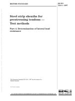
Table B.1 — Sloping gradients
Percentage
%
Angle
α°
Ratio
5,24
3
1:19,1
8,33
4,76
1:12
10
5,71
1:10
12,5
7,13
1:8
17
9,65
1:5,9
18
10,28
1:5,5
Figure B.1 — Schematical indication of sloping gradients
23