Bsi bs en 15181 2017
Bạn đang xem bản rút gọn của tài liệu. Xem và tải ngay bản đầy đủ của tài liệu tại đây (9.51 MB, 30 trang )
BS EN 15181:2017
BSI Standards Publication
Measuring method of the
energy consumption of gas
fired ovens
BS EN 15181:2017
BRITISH STANDARD
National foreword
This British Standard is the UK implementation of EN 15181:2017. It
supersedes BS EN 15181:2008 which is withdrawn.
The UK participation in its preparation was entrusted to Technical
Committee GSE/35, Gas cooking appliances (domestic).
A list of organizations represented on this committee can be
obtained on request to its secretary.
This publication does not purport to include all the necessary
provisions of a contract. Users are responsible for its correct
application.
© The British Standards Institution 2017.
Published by BSI Standards Limited 2017
ISBN 978 0 580 88967 7
ICS 97.040.20
Compliance with a British Standard cannot confer immunity from
legal obligations.
This British Standard was published under the authority of the
Standards Policy and Strategy Committee on 31 March 2017.
Amendments/corrigenda issued since publication
Date
Text affected
BS EN 15181:2017
EN 15181
EUROPEAN STANDARD
NORME EUROPÉENNE
EUROPÄISCHE NORM
March 2017
ICS 97.040.20
Supersedes EN 15181:2008
English Version
Measuring method of the energy consumption of gas fired
ovens
Méthode de mesurage de la consommation d'énergie
des fours à gaz
Bestimmung des Energieverbrauchs von Gasbacköfen
This European Standard was approved by CEN on 16 January 2017.
CEN members are bound to comply with the CEN/CENELEC Internal Regulations which stipulate the conditions for giving this
European Standard the status of a national standard without any alteration. Up-to-date lists and bibliographical references
concerning such national standards may be obtained on application to the CEN-CENELEC Management Centre or to any CEN
member.
This European Standard exists in three official versions (English, French, German). A version in any other language made by
translation under the responsibility of a CEN member into its own language and notified to the CEN-CENELEC Management
Centre has the same status as the official versions.
CEN members are the national standards bodies of Austria, Belgium, Bulgaria, Croatia, Cyprus, Czech Republic, Denmark, Estonia,
Finland, Former Yugoslav Republic of Macedonia, France, Germany, Greece, Hungary, Iceland, Ireland, Italy, Latvia, Lithuania,
Luxembourg, Malta, Netherlands, Norway, Poland, Portugal, Romania, Serbia, Slovakia, Slovenia, Spain, Sweden, Switzerland,
Turkey and United Kingdom.
EUROPEAN COMMITTEE FOR STANDARDIZATION
COMITÉ EUROPÉEN DE NORMALISATION
EUROPÄISCHES KOMITEE FÜR NORMUNG
CEN-CENELEC Management Centre: Avenue Marnix 17, B-1000 Brussels
© 2017 CEN
All rights of exploitation in any form and by any means reserved
worldwide for CEN national Members.
Ref. No. EN 15181:2017 E
BS EN 15181:2017
EN 15181:2017 (E)
Contents
Page
European foreword....................................................................................................................................................... 4
Introduction .................................................................................................................................................................... 5
1
Scope .................................................................................................................................................................... 6
2
Normative references .................................................................................................................................... 6
3
Terms and definitions ................................................................................................................................... 7
4
4.1
4.2
List of measurements .................................................................................................................................... 7
Dimensions and mass .................................................................................................................................... 7
Energy consumption and heating time ................................................................................................... 7
5
5.1
5.2
5.3
5.4
5.5
5.6
5.7
5.8
General conditions for measurements .................................................................................................... 8
General ................................................................................................................................................................ 8
Ambient temperature .................................................................................................................................... 8
Test gases and test pressures ..................................................................................................................... 9
Electrical supply .............................................................................................................................................. 9
Load ...................................................................................................................................................................... 9
Instrumentation .............................................................................................................................................. 9
Positioning of the appliance ..................................................................................................................... 10
Auxiliary electrical energy........................................................................................................................ 10
6
6.1
6.2
6.2.1
6.2.2
6.2.3
6.2.4
6.2.5
6.3
Calculated oven volume and mass ......................................................................................................... 10
Calculation of the oven volume ............................................................................................................... 10
General ............................................................................................................................................................. 10
Introduction ................................................................................................................................................... 10
Usable height ................................................................................................................................................. 12
Usable width .................................................................................................................................................. 12
Usable depth .................................................................................................................................................. 12
Calculated volume........................................................................................................................................ 13
Mass of the oven............................................................................................................................................ 13
7
7.1
7.2
7.2.1
7.2.2
7.2.3
Energy consumption and time................................................................................................................. 13
Measurement of oven temperature ....................................................................................................... 13
Energy consumption and time for heating a load............................................................................. 13
Purpose ............................................................................................................................................................ 13
Preparation .................................................................................................................................................... 13
Measurement ................................................................................................................................................. 14
8
Data to be provided for the technical file ............................................................................................ 18
9
9.1
9.2
9.3
9.4
Uncertainty and verification procedures ............................................................................................ 19
Energy consumption ................................................................................................................................... 19
Oven volume .................................................................................................................................................. 19
Measured oven temperature ................................................................................................................... 19
Mass of the oven............................................................................................................................................ 19
Annex A (normative) Description of the test brick and position of the thermocouples ................. 20
A.1
Specification ................................................................................................................................................... 20
A.2
Position of the thermocouples ................................................................................................................ 20
Annex B (informative) Explanation of the formulae .................................................................................... 21
2
BS EN 15181:2017
EN 15181:2017 (E)
B.1
Explanation of the Formulae Subscripts .............................................................................................. 21
B.2
Explanation of the Formulae Superscripts .......................................................................................... 21
Annex C (normative) Calculation sheet ............................................................................................................. 22
Annex D (informative) Marking the temperature setting for checking the oven temperature .... 24
Annex ZA (informative) Coverage of Requirements of Delegated Regulation (EC) No
65/2014/EU and of Commission Regulation No 66/2014/EU ..................................................... 25
Bibliography ................................................................................................................................................................. 26
3
BS EN 15181:2017
EN 15181:2017 (E)
European foreword
This document (EN 15181:2017) has been prepared by Technical Committee CEN/TC 49 “Gas cooking
appliances”, the secretariat of which is held by UNI.
This European Standard shall be given the status of a national standard, either by publication of an
identical text or by endorsement, at the latest by September 2017, and conflicting national standards
shall be withdrawn at the latest by September 2017.
Attention is drawn to the possibility that some of the elements of this document may be the subject of
patent rights. CEN shall not be held responsible for identifying any or all such patent rights.
This document supersedes EN 15181:2008.
This document has been prepared under a mandate given to CEN by the European Commission and the
European Free Trade Association, and supports essential requirements of EU Directive(s).
For relationship with EU Directive(s), see informative Annex ZA, which is an integral part of this
document.
The main changes to the previous version of EN 15181:2008 are the following:
— the implementation of Annex ZA which shows the coverage of Regulation 66/2014 concerning
Ecodesign requirements for domestic ovens, hobs and range hoods and of Delegated Regulation
65/2014 on the Energy Labelling of domestic ovens and range hoods;
— the verification procedure for ensuring that the temperature inside the oven cavity reaches the
temperature setting of the thermostat and/or the oven control display within the duration of the
test cycle for measuring the energy consumption;
— the revision of Clause 9, Uncertainty and verification procedures;
— the amending of Clause 6, Calculated oven volume and mass, to ensure high reproducibility.
According to the CEN-CENELEC Internal Regulations, the national standards organisations of the
following countries are bound to implement this European Standard: Austria, Belgium, Bulgaria,
Croatia, Cyprus, Czech Republic, Denmark, Estonia, Finland, Former Yugoslav Republic of Macedonia,
France, Germany, Greece, Hungary, Iceland, Ireland, Italy, Latvia, Lithuania, Luxembourg, Malta,
Netherlands, Norway, Poland, Portugal, Romania, Serbia, Slovakia, Slovenia, Spain, Sweden, Switzerland,
Turkey and the United Kingdom.
4
BS EN 15181:2017
EN 15181:2017 (E)
Introduction
The object of this European Standard is to specify, in accordance with Regulation 66/2014 concerning
Ecodesign requirements for domestic ovens, hobs and range hoods and of Delegated
Regulation 65/2014 on the Energy Labelling of domestic ovens and range hoods:
— energy consumption using a standardized load during a standardized procedure,
— some performance characteristics (like volume, correspondence between set and measured oven
temperature, permitted tolerances to values declared by the manufacturer and control procedures
for checking the declared values).
5
BS EN 15181:2017
EN 15181:2017 (E)
1 Scope
This European Standard specifies the method of test for determining the gas energy consumption in
gas-fired domestic ovens when they are being used in one or more of the oven cooking modes defined
in 3.1. It applies to the gas-fired domestic ovens which are capable of utilizing gases of group H or
group E, possibly after conversion according to instructions for use.
This European Standard applies to these gas-fired domestic ovens, whether they are separate
appliances or component parts of domestic cooking appliances.
This European Standard also applies to domestic appliances that can utilize gas and/or electrical energy
to provide heat for cooking when the ovens are utilizing gas energy to provide heat for cooking, but not
when electric energy is used to provide any or all of the heat for cooking in the oven.
It is not applicable to:
— microwave combination ovens;
— small cavities ovens (3.2);
— oven cavities not provided with devices to detect and control the temperature for the preparation
of food;
— cooking modes others than defined in 3.1.1 and 3.1.2;
— ovens connected to a chimney in which the gas energy for cooking provides, by design, also space
and/or water heating;
— appliances designed for use with gases of the third family only.
This European Standard is concerned neither with safety nor with overall performance requirements.
2 Normative references
The following documents, in whole or in part, are normatively referenced in this document and are
indispensable for its application. For dated references, only the edition cited applies. For undated
references, the latest edition of the referenced document (including any amendments) applies.
EN 30-1-1:2008+A3:2013, Domestic cooking appliances burning gas - Part 1-1: Safety - General
EN 30-1-2:2012, Domestic cooking appliances burning gas - Safety - Part 1-2: Appliances having forcedconvection ovens and/or grills
EN 30-1-4:2012, Domestic cooking appliances burning gas - Safety - Part 1-4: Appliances having one or
more burners with an automatic burner control system
EN 60584-1:2013, Thermocouples — Part 2: Tolerances (IEC 60584-1)
6
BS EN 15181:2017
EN 15181:2017 (E)
3 Terms and definitions
For the purposes of this document, the terms and definitions given in EN 30-1-1:2008+A3:2013,
EN 30-1-2:2012 or EN 30-1-4:2012, provided the appliance falls within the scope of that standard, and
the following apply.
3.1
oven cooking modes
3.1.1
conventional oven cooking mode
operation of the oven for cooking roasts, pastry, etc., in which the transmission of heat is achieved by
natural convection and radiation
3.1.2
forced-convection oven cooking mode
operation of the oven for cooking roasts, pastry, etc., in which the transmission of heat by convection is
assisted by means of a fan
3.2
small cavity ovens
oven with the following dimensions related to the usable volume:
— both width and depth < 250 mm
— or height < 120 mm
Note 1 to entry:
load.
The definition of small cavity ovens in this standard is due to the size of the artificial standard
3.3
multiple cavity appliances
appliance that has more than one separate oven cavity in which food is cooked and which can be
controlled independently, but cannot be installed separately
3.4
auxiliary electrical energy
electrical energy consumption (during the brick test) of any electric components that cannot be
switched off from the control panel by the user when using the oven in accordance with the instructions
for use
4 List of measurements
4.1 Dimensions and mass
Dimensions of the calculated oven volume (see 6.2) and mass of the oven (see 6.3).
4.2 Energy consumption and heating time
Heating of the load (7.2).
7
BS EN 15181:2017
EN 15181:2017 (E)
5 General conditions for measurements
5.1 General
According to good laboratory practice, before installation, it shall be checked that the appliance is free
from damage and complies with EN 30-1-1:2008+A3:2013, 6.1.1, Soundness, EN 30-1-2 or EN 30-1-4, as
applicable.
The instructions for use regarding installation of the oven shall be followed.
Prior to every test, the whole appliance (this includes the material and the insulation) shall be at
ambient temperature. In multiple cavity appliances, each oven cavity shall be measured separately.
Only the cavity measured shall be switched on.
In case an oven has several cooking modes as described in Clause 3, the manufacturer can choose the
variant to be tested. This shall be reported (see Clause 8).
Unless otherwise specified, measurements are conducted under the following conditions:
5.2 Ambient temperature
The tests are carried out in a substantially draught-free room in which the ambient temperature is
maintained at (23 ± 2) °C during the complete test.
Prior to the measurement the whole appliance (this includes the material and the insulation) shall be at
ambient temperature of (23 ± 2) °C.
A change in the ambient temperature of the room during the test could affect the results. Care should be
taken during the test to ensure that the ambient temperature is as steady as possible.
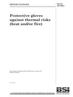
This ambient temperature is measured at a point that is at the same height as the centre of the
calculated oven volume of the oven cavity and at a distance of 0,5 m diagonally from one of the front
edges of the appliance; see Figure 1.
The measurement of the ambient temperature shall not be influenced by the oven itself or by any other
appliance.
Dimensions in millimetres
Key
1 top view
2 oven
3 thermocouple
8
Figure 1 — Position of the thermocouple
BS EN 15181:2017
EN 15181:2017 (E)
5.3 Test gases and test pressures
The appliance is fitted with the appropriate injector(s) for utilization of gas group H or gas group E. The
primary air adjuster, if any, shall be adjusted according to the technical instructions.
The appliance is then supplied with G 20, with a composition of at least 95 % methane, at a pressure of
20 mbar.
5.4 Electrical supply
The supply voltage shall be maintained at 230 V ± 1 %. The supply frequency shall be at 50Hz ± 1 %.
5.5 Load
The load for test 7.2 shall be a brick with two holes for temperature measurements as shown in
Annex A.
Before using it for the first time a new brick shall be dried in forced air circulation in an oven of about
50 l volume at ≥ 175 °C for three hours. No more than two bricks shall be dried at the same time in the
same oven.
The mass md of the completely dry brick without thermocouples shall be measured within 5 min after
removal from the oven and shall be noted in grams. The dry mass md shall be in accordance with the dry
mass specified in Annex A. The brick shall be identified with a reference number for accurate
calculation of the water absorption according to 7.2.2.
Place markings 32 mm from the measuring point of the two thermocouples with steel tube and insert
the thermocouples into the holes until the marking matches with the surface of the brick. The
thermocouples shall be fixed to ensure that the measuring points remain at a depth of 32 mm during
the whole test procedure.
The weighing machine should be protected from the effects of the hot brick.
The thermocouples may be fixed by means of a droplet of silicon glue at the surface of the brick or by
other suitable means.
Care should be taken, that the measuring point is the first contact point of the two thermowires.
Between test series, the brick should be stored in a refrigerator, preferably not soaked with water. The
brick soaking water should be kept away (to reduce dissolving processes); i.e. re-use of the brick
storage water. A brick that has already been soaked in water needs at least eight hours to be dried as
described above.
Due to the porosity of the brick care should be taken that the holes of the brick are not enlarged if the
thermocouples are removed and reinserted.
NOTE
A brick can be used for about 20 tests when handled with normal care.
5.6 Instrumentation
Air temperature measurements in the empty oven are made with a thermocouple with a welded point
(not with a black copper plate), class 1, type K.
Room temperature measurements are made with a thermocouple, class 1, type T.
Other types of thermocouple may be used for the measurement of room temperatures provided they
are known to provide equivalent or better accuracy and reproducibility than a type T.
Temperature measurements in the load are made with two thermocouples with 1 mm steel tube
diameter, class 1, according to EN 60584-2. The thermocouple shall be accurate to ± 1,5 K.
NOTE
The steel tube of the thermocouple eases the insertion of the thermocouple into the brick. See also 5.5,
6th paragraph.
9
BS EN 15181:2017
EN 15181:2017 (E)
The temperature measurement system, excluding the thermocouple shall be accurate to ± 1,0 K.
The determination of the heat input and the consumption shall be made at an accuracy as defined in
EN 30-1-1:2008+A3:2013, 7.3.1.2.1.1.
The equipment used shall be capable of measuring the following parameters with the specified
accuracies:
— auxiliary electrical energy within ± 1,5 % or ± 10 Wh of the measured value, whichever is the
greater,
— voltage within ± 0,5 %,
— frequency within ± 0,5 %,
— mass within ± 3 g,
— time within ± 5 s.
5.7 Positioning of the appliance
The appliance shall be installed according to the instructions for use and in accordance with
EN 30-1-1:2008+A3:2013, 7.1.3.3, EN 30-1-2:2012 and EN 30-1-4:2012, as applicable.
5.8 Auxiliary electrical energy
The auxiliary electrical energy as defined in 3.4 is measured during the brick test (7.2.3). The
measurement is taken over the same period of time as the gas consumption measurement at the
temperature T2i.. of Table 1.
6 Calculated oven volume and mass
6.1 Calculation of the oven volume
The calculated oven volume is calculated as described in 6.2.
6.2 General
6.2.1 Introduction
Removable items specified in the instructions for use to be not essential for the operation of the
appliance in the manner for which it is intended, shall be removed before measurement is carried out.
Safety operation should be guaranteed. Parts necessary for the safety of the appliance cannot be
removed for measuring the calculated volume.
NOTE
Removable shelf holders are removed.
The measurement of the calculated oven volume shall be carried out at ambient temperature.
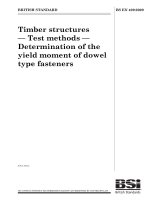
The height, width and depth of the calculated volume in the cavity shall be measured in accordance with
6.2.2 to 6.2.4. The measurement procedure is also shown in Figure 2.
10
BS EN 15181:2017
EN 15181:2017 (E)
Key
d usable depth
g heating element
h usable height
w usable width
Figure 2 — Usable internal dimensions and calculation of the volume of ovens - Measurement
procedure
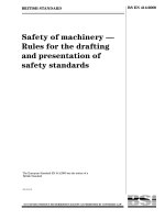
For verification purposes a gauge, as shown in Figure 3, shall be used to determine all of the three
dimensions. The gauge shall be used without appreciable force. Dimensions are stated in millimetres.
11
BS EN 15181:2017
EN 15181:2017 (E)
Key
D
= 200 mm or 120 mm
X
= dimension to be measured
(See 6.2.2, 6.2.3 and 6.2.4.)
Figure 3 — Usable internal dimensions and calculation of the volume of ovens — Gauge for
determining the calculated volume
6.2.2 Usable height
The usable height is the maximum length of a cylinder with a diameter of 200 mm reaching vertically
from the centre of the cavity floor to the lowest point on the ceiling. The lowest point of the ceiling can
be constituted by a lamp, a grill burner or electrical heating element or similar object in the area of the
cylinder.
The base of the cavity covering the oven burner, if removable, shall not be removed.
In the event that either the width or the depth of the cavity is less than 250 mm, the diameter of the
cylinder to be measured shall be reduced to 120 mm.
NOTE
The centre of the cavity bottom is defined by the middle of the usable depth and the middle of the
usable width.
6.2.3 Usable width
The usable width is the maximum length of a cylinder with a diameter of 200 mm reaching horizontally
from the left-hand side wall to the right-hand side wall of the cavity.
In the event that either the height or the depth of the cavity is less than 250 mm, the diameter of the
cylinder to be measured shall be reduced to 120 mm.
NOTE
The centre of the side wall of the cavity is defined by the middle of the usable depth and the middle of
the usable height.
6.2.4 Usable depth
The usable depth is the maximum length of a cylinder with a diameter of 200 mm reaching horizontally
from the centre of the rear wall to the inner face of the closed door.
In the event that either the width or the height of the cavity is less than 250 mm, the diameter of the
cylinder to be measured shall be reduced to 120 mm.
For measuring the usable depth, the gauge is placed on a support in such a way that the axis lies
horizontally in the centre of the cavity, the axis being extended slightly over the expected usable depth.
The door is closed carefully so that the gauge is compressed to give the usable depth.
12
BS EN 15181:2017
EN 15181:2017 (E)
NOTE
The centre of the rear wall of the cavity is defined by the middle of the usable height and the middle of
the usable width.
6.2.5 Calculated volume
The calculated volume is determined from these three dimensions and is stated in litres rounded to the
next full litre.
6.3 Mass of the oven
The mass of the oven, including accessories needed to perform the test of Clause 7, is determined and
expressed in kilograms, rounded to first decimal place.
NOTE
In case of ovens integrated in free-standing appliances the mass of the appliance is considered.
7 Energy consumption and time
7.1 Measurement of oven temperature
The oven temperature of each cooking mode, as appropriate (see Clause 3), shall be measured
separately. During the test only one cooking mode (see Clause 3) shall be used.
The air temperature in the empty oven is measured with a thermocouple, according to 5.6, fixed to the
grid which is delivered with the oven and placed in the oven in a way that the welded point of the
thermocouple is located at the centre of the useful volume of the oven with a distance of at least 30 mm
from the grid.
7.2 Energy consumption and time for heating a load
7.2.1 Purpose
The purpose of this test is to measure the energy consumption and the time for heating a load. The load
is a water saturated brick as defined in 7.2.2 which simulates both the thermal properties and the water
content of food (e.g. meat).
7.2.2 Preparation
Before heating the brick, which has been treated according to 5.5, it shall be put into a water container
so that it is completely covered with water of less than 20 °C. The water container with the brick is
placed for at least 8 h into a temperature controlled environment, for example a refrigerator and cooled
down until the centre temperature of the brick (both thermocouples) is (5 ± 2) °C.
A hot brick shall be cooled down in air to a centre temperature below 25 °C before putting it into the
cold water.
NOTE 1
A hot brick put directly into cold water would absorb substantially more water due to the capillary
effect and different water viscosity at different temperatures.
NOTE 2
The brick gets approximately the same water content each time it is soaked in water. It is not
necessary to dry it completely between uses.
When the water saturated brick with the thermocouples is taken out of the water container, excessive
water is allowed to drip off for 1 min. The mass of the wet brick mw shall be measured and the absorbed
amount of water (Wabs) is determined in g taking into account the mass of the thermocouples by
calculating Wabs = mw - md (md measured according to 5.5). The amount of absorbed water shall be as
specified in Annex A.
Immediately before placing the brick of the oven, the temperature of the brick is checked. Both
thermocouples (T1, T2) shall read (5 ± 2) °C.
13
BS EN 15181:2017
EN 15181:2017 (E)
7.2.3 Measurement
7.2.3.1 Procedure
Each appliance is tested in accordance with the setting values given in Table 1.
With the appliance at ambient temperature in accordance with 5.2, the brick, prepared according to
7.2.2, is placed in the geometric centre of the calculated oven volume with its largest surface centrally
on the grid delivered with the oven, with the thermocouples on the upper side. The grid is inserted into
the shelf support level of the oven which ensures that the centre of the brick comes as close as possible
to the centre but not higher (if this arrangement is not possible, use an arrangement which is as close to
the centre as possible) than the centre of the calculated oven volume. The longer axis of the brick shall
be parallel with the oven front.
Where the grid can be inserted in two different positions (e.g. upside down gives a different height), the
position should be such as to ensure that the centre of the brick comes as close as possible to, but not
higher than, the centre of the calculated oven volume.
The thermocouples shall be led through the door gap in a way that the door is completely closed
without applying additional force.
The measurement shall be started by switching on the oven within three minutes from the removal of
the brick from the refrigerator. The temperature control is set to positions where the mean oven
temperature rises ∆Tki… as defined in Table 1 can be expected. ∆Tki… is the difference between the
average ambient temperature and the actual oven temperature (measured in 7.2.3.2), k = 1, 2, 3.
The temperature in the centre of the oven at the beginning of the test (Toi) in °C is determined as
described in 7.1.
NOTE
To avoid possible modification of the temperature control set, it is suggested to fix the knob at the
control temperature.
The average ambient temperature (Tav) during the test is determined by the arithmetic mean of the
ambient temperatures measured in accordance with 5.2 at the beginning of the test (Tr1) (i.e. when
switching on the oven) and when the two thermocouples in the brick have reached a centre
temperature rise of 55 K (Tr2).
Table 1 — Oven settings
Oven temperature
rise
∆T1i
∆T2i
∆T3i
a
Heating functions
Conventional
“ic”
Forced air
“if”
(140 −0/+10) K
(150 ± 5) K
(220 ± 5) Ka
(180 ± 5) Ka
(180 ± 5) K
(165 ± 5) K
Or the maximum temperature rise if this value cannot be reached.
7.2.3.2 Checking the oven temperature
After the test according to 7.2.3.1, the brick is removed from the oven and the oven is run for some extra
i
time without changing the setting. The oven temperature Tk, measured is determined in line with 7.1 as the
arithmetic mean between the maximum and minimum temperatures at steady-state conditions.
14
BS EN 15181:2017
EN 15181:2017 (E)
NOTE 1
Ovens with thermostats according to EN 257: steady-state conditions are deemed to be achieved when
the temperature does not change by more than ± 2 K over a period of 10 min or 1 h after removal of the brick.
NOTE 2
Ovens with automatic burner control system according to EN 298: steady-state conditions are
considered to be achieved when the arithmetic mean value between the maximum and the minimum temperature
of each cycle of the control device does not change by more than ± 2 K over a period of at least 5 cycles.
7.2.3.3 Checking the correspondence between set and measured oven temperature
Immediately after the test of 7.2.3.2 the temperature setting Tksi shall be noted, where Tksi is the
temperature setting of the knob controlling the thermostat and/or the oven control display (s - setting).
In case when the Tksi does not correspond to a value (see, as an example, Figure 4) or a reference
marked on the knob or panel, the value of Tksi is obtained by applying the polar coordinate paper
between the next marked values or references before and after Tksi .
Figure 4 — Setting of the thermostat knob
NOTE 1
If the setting of the knob is marked by means of a number (e.g. 140), the knob is positioned at the
geometrical centre of the circle circumscribing the figure.
If the setting is marked by symbols (e.g. * or • or ♦), figures or words the relevant set temperature
should be indicated in the instructions for use.
NOTE 2
i
In case when Tks corresponds to a value or a reference marked on the knob or panel or on the oven
control display,
i
Tk, measured
corresponds to Tof.
If the temperature steps are not clearly marked, the setting temperature should be determined by the
angle considering the visible marks on the knob using polar coordinate paper (see Annex D).
i
The measured oven temperature Tk, measured stated.
i
The difference between Tksi and Tk, measured calculated according to Formulae (1) and (2), where n = 3.
i
i
∆Tk, setting
=−
Tks i Tk, measured
1
n
i
i
∆Tsetting =k=1 ∆Tk,setting
n
∑
(1)
(2)
15
BS EN 15181:2017
EN 15181:2017 (E)
7.2.3.4 Determination of the gas energy consumption and the time for heating the load
The gas energy consumption, Eki , is determined using the formula:
c × Hs
Eki= V
where
Vc
Hs
(3)
is the volume of dry gas consumed, corrected to reference conditions (15 °C and
1 013,25 mbar), in cubic metres;
is the gross calorific value of the dry test gas under reference conditions (15 °C and
1 013,25 mbar), in Megajoule per cubic metre. (See EN 30–1–1:2008+A3:2013, 3.3.1.5).
Where the test gas G20 has a methane content of less than 99,5 % care should be taken to ensure that
the calorific value of this gas is known and used in the above formula.
Vc is determined from the measured volume, by the following formula:
pa + p − pw
Vc =
Vmes ⋅
where
Vmes
pa
p
pw
tg
1 013, 25
⋅
288,15
273,15 + tg
(4)
is the measured gas volume, in cubic metres;
is the atmospheric pressure, in millibars;
is the gas supply pressure measured at the same point as that used in the heat input
determination, in millibars;
is the partial vapour pressure, in millibars;
is the gas temperature measured at the same point as that used in the heat input
determination, in degrees Celsius.
The gas energy consumptions E1i , E2i , E3i correspond to the temperatures of Table 1, as appropriate.
The following data are measured:
— the gas volume Vmes and the time(s) tki… in min and s, as appropriate, when the two thermocouples
in the brick reach a temperature rise of 55 K, k = 1, 2, 3;
— centre temperatures of the brick in °C;
— ambient temperature at the start of the test (when the oven is switched on) and at the end of the
test (i.e. when the two thermocouples in the brick have reached 55 K temperature rise) in °C.
7.2.3.5 Checking of the water loss
At the end of the test the amount of the water loss in g (Wloss) is determined taking into account the
mass of the wet brick mw, measured according to 7.2.2 and the mass (me) measured immediately after
the removal of the brick from the oven, by calculating Wloss = mw - me.
The weighing machine should be protected from the effects of the hot brick.
After each test the oven shall be cleaned.
16
BS EN 15181:2017
EN 15181:2017 (E)
7.2.3.6 Acceptance verification of the test results (set temperature and confidence of the
measurement)
Results of the tests according to 7.2.3.1 shall only be accepted if:
a) the mean temperature rises ∆Τki... are within the temperatures specified in Table 1, and
b) the standard deviation σi as defined in Formula (5) is below 0,25 MJ.
The standard deviation σi is calculated from the data pairs ∆Τki... / Eki…
… measured according to 7.2.3.1
and calculated according to Formula (3) for each tested function, k = 1, 2, 3 drawn from the modified
Formulae (5).29a and 5.69 of Applied Statistics by Lothar Sachs:
σ
i...
=f
where
Factor ʄ
)
2
/ Qxi...
(5)
n−2
is a value based on the oven temperature ranges in Table 1 for which the maximum
value is 1,35. For the purpose of this standard this value is used.
n
NOTE
(
Qyi... − Qxyi...
is the number of measuring points, for the purpose of this standard n = 3;
Factor f was calculated with the following formula
n
=
Qyi… ∑( Eki…
(∑
) −
2
k =1
n
E i…
k =1 k
)
n
k=1
k=1
n
k=1
(
∆T
i...
=
1
n
n
)
n
i...
2
∑ ∆Tk
− k=1
n
∑ ∆T
k =1
1 n
Εi…= ∑Εik…
n k =1
i...
k
n
− ∆T i...
)
2
Qxi...
(6)
i...
Qxy
=∑ ∆Tki... ⋅ Eki... − E i... ∑ ∆Tki...
Qxi... =∑ ∆Tki...
i...
0
2
n
n
f i... =
1 (T
1+ +
2
(7)
(8)
(9)
(10)
17
BS EN 15181:2017
EN 15181:2017 (E)
8 Data to be provided for the technical file
a) Type of the oven, available cooking mode(s) according to Clause 3;
b) tested functions or variant;
c) calculated oven volume in litres, according to Clause 6;
d) supply voltage at which the measurements were made in V;
e) frequency in Hz.
f)
gas energy consumption ( Eki ) in MJ according to 7.2.3 to two decimals;
g) time(s) in min, according to 7.2.3 rounded off to the nearest half minute;
h) gross calorific value of the test gas in MJ/m3;
i)
j)
gas pressure at the meter in mbar;
measured heat input (Qn) in kW as determined in EN 30-1-1:2008+A3:2013, 7.3.1.2.1;
k) measured gas volume (Vmes m3);
l)
initial room temperature (Tr1) in °C;
m) final room temperature (Tr2) in °C;
n) temperature of the centre of the oven at the beginning of the test (Toi) in °C;
o) reference number of the brick;
p) initial temperature of the brick (T1, T2) in °C;
q) mass of the dry brick (md) in g;
r)
s)
t)
water absorption of the brick according to 7.2.2 (Wabs) in g;
water loss at the end of the test (Wloss) in g;
end cooking mass (me) of the brick after the test in g;
i
u) final oven temperature ( Tk, measured ) in °C;
v) corrected gas volume (Vc) in m3;
w) gas temperature (tg) in °C;
x) auxiliary electrical energy in Wh;
y)
18
Tksi Setting temperature.
BS EN 15181:2017
EN 15181:2017 (E)
9 Uncertainty and verification procedures
9.1 Energy consumption
If the result of the test on the first appliance exceeds the value declared by the manufacturer by more
than + 5 % the test is repeated, if appropriate, using the reference gas G20 with a composition of at least
99,5 % of methane.
If the result of this test still exceeds the value declared by the manufacturer by more than +5 % the test
is repeated with three other appliances from the same model chosen at random from the market. As an
alternative, the three additional units selected may be of one or more different models which have been
listed as equivalent product in the supplier’s technical documentation.
This test is carried out using G20 with a composition of at least 99,5 % of methane.
The arithmetic mean of the values as measured for the three appliances shall not exceed the value
declared by the manufacturer by more than + 5 %.
The value measured for the auxiliary electrical energy shall not exceed the value declared by the
manufacturer by more than + 5 %.
9.2 Oven volume
The volume determined according to Clause 6 shall not be lower than the value declared by more than
5 %.
If the result of the test carried out on the first appliance is lower than the value declared by the
manufacturer by more than 5 %, the test shall be carried out on a further three appliances, which shall
be randomly selected from the same model from the market. As an alternative, the three additional
units selected may be of one or more different models which have been listed as equivalent product in
the supplier’s technical documentation.
The arithmetical mean of the values of these three appliances shall not be lower than the value declared
by the manufacturer by more than 5 %.
9.3 Measured oven temperature
i
∆Tsetting
according to 7.2.3.2 shall be ≤ 20 K.
i
If ∆Tsetting according to 7.2.3.2 is greater than 20 K the test shall be carried out on further three
appliances, which shall be randomly selected from the same model from the market. As an alternative,
the three additional units selected may be of one or more different models which have been listed as
equivalent product in the supplier’s technical documentation.
The arithmetical mean of the values of these three appliances shall not be greater than 20 K.
NOTE
The tolerance of 20 K is needed due to the long chain of tolerances (e.g. thermostat, connection, power
of heating elements, control element and printing) and the fact that the temperature scale covers different heating
modes.
9.4 Mass of the oven
The mass of the oven according to 6.3 shall not be greater than the value declared by the manufacturer
+5 %.
If the result of the test carried out on the first oven is greater than the declared value +5 %, the test shall
be carried out on further three ovens, which shall be randomly selected from the same model from the
market. As an alternative, the three additional units selected may be of one or more different models
which have been listed as equivalent product in the supplier’s technical documentation.
The arithmetical mean of the values of these three ovens shall not be greater than the declared value
+5 %.
19
BS EN 15181:2017
EN 15181:2017 (E)
Annex A
(normative)
Description of the test brick and position of the thermocouples
A.1 Specification
Bulk density, dry:
(550 ± 40) kg/m3;
Dry mass:
(920 ± 75) g (without thermocouples), see 5.5;
Total porosity:
Water absorption:
Height:
Length x width x height:
77 %;
(1 050 ± 50) g, see 7.2.2;
(64 ± 0,5) mm.
230 mm x 114 mm x 64 mm (see sketch in A.2),
Machined on all 6 surfaces, tolerances ± 0,5 mm.
NOTE
The brick is brittle.
Tolerances of dry mass, water absorption and height are critical and shall be checked.
A.2 Position of the thermocouples
The positioning of the thermocouples is described in Figure A.1.
Key
1 metal sheet tube thermocouples
The diameter of the hole need not and should not be bigger than the diameter of the thermocouple.
If it is not possible to drill the holes 32 mm deep, drill the holes to a depth of about 25 mm, insert the
thermocouples into the holes and push them carefully further down the remaining 7 mm. Alternatively
a self-made rigid wire with 1 mm diameter and 32 mm long could serve as a drill.
Figure A.1 — Positioning of the thermocouples
20
BS EN 15181:2017
EN 15181:2017 (E)
Annex B
(informative)
Explanation of the formulae
B.1 Explanation of the Formulae Subscripts
r
= room
0
= nominal value
T
t
1
w
d
k
= temperature
= time
= index to count measurement, for example 1 to 3
= wet or water
= dry
= summing index
B.2 Explanation of the Formulae Superscripts
i
c
f
= cooking mode
= convection
= forced air
21
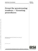
22
Figure C.1 — Data collection and calculation sheet for conventional heating gas ovens
Calculation sheet
Annex C
(normative)
BS EN 15181:2017
EN 15181:2017 (E)
Figure C.2 — Data collection and calculation sheet for forced-convection gas ovens
BS EN 15181:2017
EN 15181:2017 (E)
23