Bsi bs en 16602 60 13 2015
Bạn đang xem bản rút gọn của tài liệu. Xem và tải ngay bản đầy đủ của tài liệu tại đây (1.53 MB, 102 trang )
BS EN 16602-60-13:2015
BSI Standards Publication
Space product assurance —
Requirements for the use of
COTS components
BS EN 16602-60-13:2015
BRITISH STANDARD
National foreword
This British Standard is the UK implementation of EN
16602-60-13:2015.
The UK participation in its preparation was entrusted to Technical
Committee ACE/68, Space systems and operations.
A list of organizations represented on this committee can be
obtained on request to its secretary.
This publication does not purport to include all the necessary
provisions of a contract. Users are responsible for its correct
application.
© The British Standards Institution 2015. Published by BSI Standards
Limited 2015
ISBN 978 0 580 86646 3
ICS 49.140
Compliance with a British Standard cannot confer immunity from
legal obligations.
This British Standard was published under the authority of the
Standards Policy and Strategy Committee on 31 August 2015.
Amendments issued since publication
Date
Text affected
BS EN 16602-60-13:2015
EN 16602-60-13
EUROPEAN STANDARD
NORME EUROPÉENNE
EUROPÄISCHE NORM
August 2015
ICS 49.140
English version
Space product assurance - Requirements for the use of COTS
components
Assurance produit des projets spatiaux - Exigences pour
l'utilisation de composants commerciaux sur étagère
Raumfahrtproduktsicherung - Anforderungen für die
Nutzung von COTS-Komponenten
This European Standard was approved by CEN on 16 November 2014.
CEN and CENELEC members are bound to comply with the CEN/CENELEC Internal Regulations which stipulate the conditions for giving
this European Standard the status of a national standard without any alteration. Up-to-date lists and bibliographical references concerning
such national standards may be obtained on application to the CEN-CENELEC Management Centre or to any CEN and CENELEC
member.
This European Standard exists in three official versions (English, French, German). A version in any other language made by translation
under the responsibility of a CEN and CENELEC member into its own language and notified to the CEN-CENELEC Management Centre
has the same status as the official versions.
CEN and CENELEC members are the national standards bodies and national electrotechnical committees of Austria, Belgium, Bulgaria,
Croatia, Cyprus, Czech Republic, Denmark, Estonia, Finland, Former Yugoslav Republic of Macedonia, France, Germany, Greece,
Hungary, Iceland, Ireland, Italy, Latvia, Lithuania, Luxembourg, Malta, Netherlands, Norway, Poland, Portugal, Romania, Slovakia,
Slovenia, Spain, Sweden, Switzerland, Turkey and United Kingdom.
CEN-CENELEC Management Centre:
Avenue Marnix 17, B-1000 Brussels
© 2015 CEN/CENELEC All rights of exploitation in any form and by any means reserved
worldwide for CEN national Members and for CENELEC
Members.
Ref. No. EN 16602-60-13:2015 E
BS EN 16602-60-13:2015
EN 16602-60-13:2015 (E)
Table of contents
European foreword.................................................................................................... 4
Introduction................................................................................................................ 4
1 Scope ....................................................................................................................... 7
2 Normative references ............................................................................................. 9
3 Terms, definitions and abbreviated terms.......................................................... 11
3.1
Terms from other standards....................................................................................11
3.2
Terms specific to the present standard ................................................................... 11
3.3
Abbreviated terms...................................................................................................12
3.4
Conventions............................................................................................................13
3.5
Nomenclature .........................................................................................................14
4 Requirements for class 1 components ............................................................... 15
5 Requirements for class 2 components ............................................................... 36
6 Requirements for class 3 components ............................................................... 59
7 Quality levels ........................................................................................................ 74
8 Evaluation and lot acceptance for retinned parts .............................................. 75
9 Pure tin lead finish – risk analysis ...................................................................... 83
Annex A (normative) Component control plan (CCP) - DRD ................................. 84
Annex B (normative) Declared components list (DCL) - DRD ............................... 85
Annex C (normative) Internal Supplier’s specification - DRD ............................... 86
Annex D (normative) Parts approval document - DRD .......................................... 88
Annex E (informative) EEE documents delivery per review .................................. 89
Annex F (normative) Justification document - DRD .............................................. 90
Annex G (informative) Difference between the three classes ............................... 93
Annex H (informative) Flow chart for construction analysis and destructive
physical analysis ................................................................................................. 94
2
BS EN 16602-60-13:2015
EN 16602-60-13:2015 (E)
Bibliography............................................................................................................. 98
Figures
Figure 4-1: Evaluation tests flow chart for Class 1 components ............................................ 21
Figure 4-2: Lot acceptance tests flow chart for Class 1 components .................................... 28
Figure 5-1: Evaluation Tests flow charts for Class 2 components ......................................... 42
Figure 5-2: Lot acceptance tests flow chart for Class 2 components .................................... 51
Figure 6-1: Lot acceptance test flow chart for Class 3 components ...................................... 67
Figure 8-1: Evaluation flow chart for retinned parts – class 1 programmes ........................... 76
Figure 8-2: Lot acceptance flow chart for retinned parts – class 1 programmes ................... 77
Figure 8-3: Evaluation flow chart for retinned parts – class 2 programmes ........................... 79
Figure 8-4: Lot acceptance flow chart for retinned parts – class 2 programmes ................... 80
Figure 8-5: Evaluation flow chart for retinned parts – class 3 programmes ........................... 81
Figure 8-6: Lot acceptance flow chart for retinned parts – class 3 programmes ................... 82
Tables
Table 4-1: Evaluation Tests for Class 1 components ............................................................ 21
Table 4-2: Screening tests for Class 1 components.............................................................. 25
Table 4-3: Lot acceptance tests for Class 1 components...................................................... 29
Table 4-4: Documentation for Class 1 components .............................................................. 35
Table 5-1: Evaluation Tests for Class 2 components ............................................................ 43
Table 5-2: Screening tests for the Class 2 components ........................................................ 48
Table 5-3: Lot acceptance tests for Class 2 components...................................................... 52
Table 5-4: Documentation for Class 2 components .............................................................. 58
Table 6-1: Evaluation tests for Class 3 components ............................................................. 63
Table 6-2: Screening tests for Class 3 components.............................................................. 65
Table 6-3: Lot acceptance tests for Class 3 components...................................................... 68
Table 6-4: Documentation for Class 3 components .............................................................. 73
Table H-1 : Construction analysis and DPA .......................................................................... 94
Table H-2 : Construction analysis sequence......................................................................... 95
Table H-3 : Destructive physical analysis sequence ............................................................. 97
3
BS EN 16602-60-13:2015
EN 16602-60-13:2015 (E)
European foreword
This document (EN 16602-60-13:2015) has been prepared by Technical
Committee CEN/CLC/TC 5 “Space”, the secretariat of which is held by DIN.
This standard (EN 16602-60-13:2015) originates from ECSS-Q-ST-60-13C.
This European Standard shall be given the status of a national standard, either
by publication of an identical text or by endorsement, at the latest by February
2016, and conflicting national standards shall be withdrawn at the latest by
February 2016.
Attention is drawn to the possibility that some of the elements of this document
may be the subject of patent rights. CEN [and/or CENELEC] shall not be held
responsible for identifying any or all such patent rights.
This document has been prepared under a mandate given to CEN by the
European Commission and the European Free Trade Association.
This document has been developed to cover specifically space systems and has
therefore precedence over any EN covering the same scope but with a wider
domain of applicability (e.g. : aerospace).
According to the CEN-CENELEC Internal Regulations, the national standards
organizations of the following countries are bound to implement this European
Standard: Austria, Belgium, Bulgaria, Croatia, Cyprus, Czech Republic,
Denmark, Estonia, Finland, Former Yugoslav Republic of Macedonia, France,
Germany, Greece, Hungary, Iceland, Ireland, Italy, Latvia, Lithuania,
Luxembourg, Malta, Netherlands, Norway, Poland, Portugal, Romania,
Slovakia, Slovenia, Spain, Sweden, Switzerland, Turkey and the United
Kingdom.
4
BS EN 16602-60-13:2015
EN 16602-60-13:2015 (E)
Introduction
This European Standard is based on and complementary to ECSS-Q-ST-60C
(with upward revisions). This standard can only be used in conjunction with
ECSS-Q-ST-60C in its current revision. This standard applies only to
commercial components - as defined in its scope - which meet defined technical
parameters that are on the system application level demonstrated to be
unachievable with existing space components or only achievable with
qualitative and quantitative penalties. The standard requires that qualitative
and quantitative penalties are specified, as applicable, as a minimum in terms of
quantifiable parameters such as: functional capability, parts count, power
dissipation, frequency of operation, data/signal processing efficiency,
interconnect complexity, mass, volume, …
For traceability to ECSS-Q-ST-60, the modifications or additions are marked in
blue. Text in black colour is unmodified text.
The objective of the EEE component selection, control, procurement and use
requirements is to ensure that EEE components used in a space project enables
the project to meet its mission requirements.
Important elements of EEE component requirements include:
a.
component programme management,
b.
component selection, evaluation and approval,
c.
procurement,
d.
handling and storage,
e.
component quality assurance,
f.
specific components, and
g.
documentation.
The main tools which can be used to reach the objective are:
a.
concurrent engineering,
b.
standardization of component types,
c.
characterization of components,
d.
assessment of component
competencies and processes,
e.
testing, screening, lot acceptance and periodic testing,
f.
procurement specifications,
g.
control and inspection,
h.
control of nonconforming materials,
i.
assessment and use of existing component data,
j.
application of specific control to mitigate risk for components with
limited data or confidence, and
manufacturers
including
declared
5
BS EN 16602-60-13:2015
EN 16602-60-13:2015 (E)
k.
information management.
The basic approach is as follows:
• The customer of a given space project defines the EEE component
requirements within the boundaries of this standard. They appear in the
appropriate clauses of the project requirements as defined in ECSS-M-ST-10.
• The supplier defines a component control plan to implement those
requirements into a system which enables, for instance, to control the
selection, approval, procurement, handling in a schedule compatible with
his requirements, and in a cost-efficient way.
• The supplier ensures that the applicable parts requirements are passed
down to lower level suppliers and ensure that they are compliant to these
parts requirements.
6
BS EN 16602-60-13:2015
EN 16602-60-13:2015 (E)
1
Scope
This standard defines the requirements for selection, control, procurement and
usage of EEE commercial components for space projects.
This standard is applicable to commercial encapsulated active monolithic parts
(integrated circuits and discrete):
•
diodes
•
microwave diodes
•
integrated circuits
•
microwave integrated circuits (MMIC)
•
transistors
•
microwave transistors
This standard is not applicable to the commercial parts from the following
families:
•
capacitors
•
connectors
•
crystals
•
filters
•
fuses
•
heaters
•
inductors
•
microwave passive parts
•
oscillators
•
relays
•
resistors
•
switches
•
thermistors
•
transformers
•
cables & wires
•
hybrids
•
surface acoustic waves (SAW)
•
charge coupled devices (CCD)
•
active pixel sensors (APS)
7
BS EN 16602-60-13:2015
EN 16602-60-13:2015 (E)
In addition, the following families of EEE components are not addressed by the
present ECSS standard but it can be used as guideline and revisited on
case/case basis:
•
photodiodes
•
light emitting diodes (LED)
•
phototransistors
•
opto-couplers
•
laser diodes
In line with ECSS-Q-ST-60, this standard differentiates between three classes of
components through three different sets of standardization requirements
(clauses) to be met.
The three classes provide for three levels of trade-off between assurance and
risk. The highest assurance and lowest risk is provided by class 1 and the lowest
assurance and highest risk by class 3. Procurement costs are typically highest
for class 1 and lowest for class 3. Mitigation and other engineering measures
can decrease the total cost of ownership differences between the three classes.
The project objectives, definition and constraints determine which class or
classes of components are appropriate to be utilised within the system and
subsystems.
a.
Class 1 components are described in Clause 4
b.
Class 2 components are described in Clause 5
c.
Class 3 components are described in Clause 6
Annex G includes a diagram that summarizes the difference between these
three classes for evaluation, screening and lot acceptance.
The requirements of this document are applicable to all parties involved at all
levels in the integration of EEE commercial components into space segment
hardware and launchers.
For easy tailoring and implementation of the requirements into a Requirement
Management Tool, and for direct traceability to ECSS-Q-ST-60, requirements in
this standards have been written in the way of a ECSS Applicability
Requirement Matrix (EARM), as defined in Annex A of ECSS-S-ST-00 “ECSS
system – Description, implementation and general requirements”.
This standard may be tailored for the specific characteristics and constrains of a
space project in conformance with ECSS-S-ST-00.
8
BS EN 16602-60-13:2015
EN 16602-60-13:2015 (E)
2
Normative references
The following normative documents contain provisions which, through
reference in this text, constitute provisions of this ECSS standard. For dated
references, subsequent amendments to, or revision of any of these publications
do not apply. However, parties to agreements based on this ECSS Standard are
encouraged to investigate the possibility of applying the more recent editions of
the normative documents indicated below. For undated references, the latest
edition of the publication referred to applies.
EN reference
Reference in text
Title
EN 16601-00-01
ECSS-S-ST-00-01
ECSS system - Glossary of terms
EN 16602-60
ECSS-Q-ST-60
Space product assurance - Electrical, electronic and
electromechanical (EEE) components
EN 16602-60-14
ECSS-Q-ST-60-14
Space product assurance - Relifing procedure - EEE
components
EN 16602-60-15
ECSS-Q-ST-60-15
Space product assurance – Radiation hardness
assurance – EEE components
ESCC 21300
Terms, definitions, abbreviations, symbols and units
ESCC 24900
Minimum
requirements
for
controlling
environmental contamination of components
ESCC 25500
Methodology for the detection of pure tin in the
external surface finish of case and leads of EEE
components
MIL-STD-750
Test methods for semiconductor devices
MIL-STD-883
Test method standard microcircuits
JESD22-A101
Steady state temperature humidity bias life test
JESD22-A110
Highly accelerated temperature and humidity stress
test
JESD22-A113
Preconditioning of plastic surface mount devices
prior to reliability testing
JESD22-A121
Test Method for Measuring Whisker Growth on Tin
and Tin Alloy Surface Finishes
JESD22-B106
Resistance to soldering temperature for through hole
mounted devices
JESD-201
Environmental Acceptance Requirements for Tin
9
BS EN 16602-60-13:2015
EN 16602-60-13:2015 (E)
Whisker Susceptibility of Tin and Tin Alloy Surface
Finishes
10
J-STD-020
Moisture/Reflow
sensitivity
classification
nonhermetic solid state surface mount devices
for
J-STD-033
Handling, packing, shipping and use of moisture/
reflow sensitive surface mount devices
BS EN 16602-60-13:2015
EN 16602-60-13:2015 (E)
3
Terms, definitions and abbreviated terms
3.1
Terms from other standards
For the purpose of this standard, the terms and definitions from ECSS-S-ST-00-01
apply.
For the purpose of this standard, the following terms and definitions from
ECSS-Q-ST-60 apply:
agent
characterization
commercial component
concurrent engineering
franchised distributor
parts engineer
parts procurer
qualified parts
screening
space qualified parts
3.2
Terms specific to the present standard
3.2.1
traceability information (trace code)
unique identifier used by manufacturers to label and trace a quantity of
components with a common manufacturing history and thereby common
characteristics.
NOTE 1 The notion of "lot of EEE parts" used for the radiation
and lot acceptance tests is defined by the trace code.
NOTE 2 Several trace codes can be part of a same delivery from
the manufacturer or the distributor.
NOTE 3 It is possible to have several diffusion lots (as per ESCC
21300) in the same trace code.
11
BS EN 16602-60-13:2015
EN 16602-60-13:2015 (E)
3.3
Abbreviated terms
For the purpose of this Standard, the abbreviated terms from ECSS-S-ST-00-01
and the following apply:
12
Abbreviation
Meaning
AOQ
average outgoing quality
ASIC
application specific integrated circuit
BGA
ball grid array
CA
construction analysis
CCD
charge coupled device
CCP
component control plan
CN
change notice
CoC
certificate of conformance
CDR
critical design review
CR
change request
DCL
declared components list
DPA
destructive physical analysis
DRD
document requirement definition
DSM
deep Sub-Micron
Ea
activation energy
ECSS
European Coordination for Space Standardization
EEE
electrical, electronic, electromechanical
EFR
early failure rate
ESCC
European space components coordination
GSE
ground support equipment
HAST
highly accelerated stress test
HTRB
high temperature reverse bias
JD
justification document
LAT
lot acceptance test
LED
light emitting diode
LVT
lot validation testing
MMIC
microwave monolithic integrated circuit
PAD
parts approval document
PCB
parts control board
PCN
process change notice
PDA
percent defective allowable
PED
plastic encapsulated device
PIND
particle impact noise detection
QBSD
full quadrant back scatter electron detector
QCI
quality conformance inspection
RFD
request for deviation
BS EN 16602-60-13:2015
EN 16602-60-13:2015 (E)
3.4
Abbreviation
Meaning
RH
relative humidity
RoHs
restriction of the use of certain hazardous
substances
RVT
radiation verification testing
SCSB
Space Components Steering Board
SAM
scanning accoustic microscopy
SEM
scanning electron microscope
SMD
surface mount device
TCI
technology conformance inspection
Tg
glassivation temperature
THB
temperature humidity bias
Tj
junction temperature
T/C
thermal cycling
Conventions
a.
The term “EEE component“ is synonymous with the terms "EEE Part",
"Component" or just "Part".
b.
The term “for approval” means that a decision of the approval authority
is necessary for continuing the process.
c.
The term “for review” means that raised reviewers comments are
considered and dispositioned.
d.
The term “for information” means that no comments are expected about
the delivered item.
e.
For the purpose of clear understanding of this document, hereunder is a
listing of component categories which are covered by the term EEE
component, encapsulated or non-encapsulated, irrespective of the quality
level:
1.
Capacitors
2.
Connectors
3.
Crystals
4.
Discrete semiconductors (including diodes, transistors)
5.
Filters
6.
Fuses
7.
Magnetic components (e.g. inductors, transformers, including inhouse products)
8.
Monolithic Microcircuits (including MMICs)
9.
Hybrid circuits
13
BS EN 16602-60-13:2015
EN 16602-60-13:2015 (E)
10.
Relays
11.
Resistors, heaters
12.
Surface acoustic wave devices
13.
Switches (including mechanical, thermal)
14.
Thermistors
15.
Wires and Cables
16.
Optoelectronic Devices (including opto-couplers, LED, CCDs,
displays, sensors)
17.
Passive Microwave Devices (including, for instance, mixers,
couplers, isolators and switches)
NOTE
3.5
Microwave switches consisting of multiple EEE
components are considered as equipment. The
requirements of this standard are applicable to the
EEE parts they incorporate and to microwave
switches having a simple design (single EEE part).
Nomenclature
The following nomenclature applies throughout this document:
a.
The word “shall” is used in this Standard to express requirements. All
the requirements are expressed with the word “shall”.
b.
The word “should” is used in this Standard to express recommendations.
All the recommendations are expressed with the word “should”.
NOTE
c.
The words “may” and “need not” are used in this Standard to express
positive and negative permissions, respectively. All the positive
permissions are expressed with the word “may”. All the negative
permissions are expressed with the words “need not”.
d.
The word “can” is used in this Standard to express capabilities or
possibilities, and therefore, if not accompanied by one of the previous
words, it implies descriptive text.
NOTE
e.
14
It is expected that, during tailoring, recommendations
in this document are either converted into
requirements or tailored out.
In ECSS “may” and “can” have completely different
meanings: “may” is normative (permission), and
“can” is descriptive.
The present and past tenses are used in this Standard to express
statements of fact, and therefore they imply descriptive text.
BS EN 16602-60-13:2015
EN 16602-60-13:2015 (E)
4
Requirements for class 1 components
Identifier
Requirement
Applicability
4.1 Component programme management
4.1.1 General
4.1.1a
4.1.2 Components control programme
Applicable
4.1.2.1 Organization
4.1.2.1a
4.1.2.1b
Applicable
4.1.2.2 Component control plan
Applicable
4.1.2.2a
Applicable
4.1.2.2b
Applicable
4.1.2.2c
Applicable
4.1.3 Parts control board
4.1.3a
Applicable
4.1.3b
Applicable
4.1.3c
Applicable
4.1.3d
Applicable
4.1.4 Declared component list
4.1.4a
Applicable
4.1.4b
Applicable
4.1.4c
Applicable
4.1.4d
After equipment CDR, all modifications affecting the JD
information shall be implemented, in the "as design" DCL, through
the CN / CR process and submitted to the customer for approval.
NOTE
Modified
For JD generation, see 4.2.4.d.
4.1.4e
Applicable
4.1.4f
Applicable
4.1.4g
Applicable
4.1.4h
Applicable
15
BS EN 16602-60-13:2015
EN 16602-60-13:2015 (E)
4.1.5 Electrical and mechanical GSE
4.1.5a
Applicable
4.1.5b
Applicable
4.2 Component selection, evaluation and approval
4.2.1 General
4.2.1a
Applicable
4.2.1b
Applicable
4.2.2 Manufacturer and component selection
4.2.2.1 General rules
4.2.2.1a
Applicable
4.2.2.1b
Applicable
4.2.2.1c
Applicable
4.2.2.1d
Applicable
4.2.2.1e
Applicable
4.2.2.1f
Applicable
4.2.2.1g
For the assessment of commercial components, the supplier shall
collect the available data on the manufacturer and the component
in the JD specified in the requirement 4.2.4d.
NOTE
New
It is important to check the exhaustiveness
of the manufacturer documentation & data
sheet with respect to e.g. the following
items:
• component marking,
• mechanical description,
• electrical and thermal description.
4.2.2.1h
For Deep Sub-Micron Technologies (<90nm), the detailed test
definition shall identify the technology through the construction
analysis and the application.
New
NOTE 1 It is important to ensure that the test
conditions remain as close as possible to
application.
NOTE 2 This requirement is important due to the
specificities
of
Deep
Sub-Micron
Technologies (<90nm).
4.2.2.2 Parts and material restriction
4.2.2.2a
Applicable
4.2.2.2b
Applicable
4.2.2.2c
Applicable
4.2.2.2d
16
For limited life duration, known instability, safety hazards or
reliability risk reasons, EEE components listed below shall not be
used:
Modified
BS EN 16602-60-13:2015
EN 16602-60-13:2015 (E)
1. EEE components with pure tin (less than 3% Pb in case
of SnPb alloy) used as a finish on the leads, terminations
and external surfaces of components and packages.
NOTE
For EEE components with pure tin, see also
requirements 4.2.2.2h and 4.2.2.2i.
2. Hollow core resistors
3. Potentiometers
monitoring)
(except
for
mechanism
position
4. Non-metallurgically bonded diodes
5. Semiconductor dice with unglassivated active area
6. Wet slug tantalum capacitors other than capacitor
construction using double seals and a tantalum case
7. Any component whose internal construction uses
metallurgic bonding with a melting temperature not
compatible with the end-application mounting
conditions
8. Wire link fuses < 5A
9. TO5 relays without double welding of the mechanism
to the header or with any type of integrated diodes
inside
4.2.2.2e
Applicable
4.2.2.2f
Applicable
4.2.2.2g
Applicable
4.2.2.2h
The use of pure tin (inside or outside the part) shall be declared in
the JD.
Modified
4.2.2.2i
To assess Pb free with tin finish whisker risk, the following actions
shall be performed by the supplier:
New
1. In order to verify information from manufacturer
(included in the JD), as part of the incoming inspection,
check the lead finish of all procured lots as per ESCC
25500 basic specification.
2. When confirmed during incoming, assess individually
each use of pure tin termination through a RFD.
3. Submit each lot confirmed with pure tin terminations to
solder dip with an SnPb solder.
NOTE
Solder dip for tin whisker mitigation
differs from solder dip for solderability in
that for tin whisker mitigation it is
required that the termination is coated
over its entire length, right up to the
package surface (no stand off).
4. Perform the retinning operation before screening and
before the lot acceptance test.
5. Before retinning of flight parts, document the hot solder
17
BS EN 16602-60-13:2015
EN 16602-60-13:2015 (E)
dip process by a procedure to be submitted to customer
for approval.
6. Perform the evaluation of retinned components in
conformance with Figure 8-1 from the requirement 8.1a.
7. Perform the lot acceptance of retinned components in
conformance with Figure 8-2 from the requirement 8.1a.
4.2.2.3 Preferred sources
4.2.2.3a
Not applicable
4.2.2.3b
Not applicable
4.2.2.3c
Applicable
4.2.2.4 Radiation hardness
4.2.2.4a
Applicable
4.2.2.4b
Applicable
4.2.2.4c
Applicable
4.2.2.4d
Applicable
4.2.2.4e
Applicable
4.2.2.4f
Applicable
4.2.2.4g
Applicable
4.2.2.4h
Applicable
4.2.2.4i
Applicable
4.2.2.5 Derating
4.2.2.5a
Applicable
4.2.2.5b
Applicable
4.2.2.6 Temperature range
4.2.2.6a
Commercial parts shall be selected in the highest available
temperature range.
New
4.2.2.6b
A minimum 10 °C margin shall be used between the maximum
manufacturer temperature range and the application temperature
range (including worst cases).
New
4.2.2.6c
In case |(manufacturer max temperature range – used max temp)|
< 10 °C, an electrical characterisation shall be performed at used
temperature with an additional margin of 10 °C during the
evaluation step.
New
NOTE 1 Example: for a manufacturer -40°C/+85°C
temperature range with an application up
to +80°C, then an electrical characterisation
is performed at +90°C.
NOTE 2 Example for a manufacturer -40°C/+85°C
temperature range with an application
down to -35°C, then an electrical
characterisation is performed at -45°C.
18
BS EN 16602-60-13:2015
EN 16602-60-13:2015 (E)
4.2.3 Component evaluation
4.2.3.1 General
4.2.3.1a
Applicable
4.2.3.1b
Applicable
4.2.3.1c
Applicable
4.2.3.1d
Applicable
4.2.3.1e
Applicable
4.2.3.1f
Applicable
4.2.3.1g
Applicable
4.2.3.1h
Applicable
4.2.3.1i
The supplier shall review the evaluation results to determine their
impact on the content of the screening and lot acceptance tests.
4.2.3.1j
Modified
Applicable
4.2.3.1k
The supplier shall prepare a preliminary internal supplier’s
specification for electrical testing during evaluation tests.
New
4.2.3.1l
The supplier specification specified in 4.2.3.1k shall as minimum
include tested parameters, test conditions, acceptance criteria, drift
limits.
New
4.2.3.1m
The supplier shall update the internal supplier’s specification used
for screening and lot acceptance in accordance with the results of
evaluation testing.
New
4.2.3.1n
The preliminary and the final internal supplier’s specification as
specificed in Annex C shall be submitted to the customer for
approval.
New
4.2.3.2 Component manufacturer assessment
4.2.3.2.1
Not applicable
See 4.2.2.1.g
4.2.3.2.2a
Not applicable
See 4.2.2.1.g
4.2.3.2.2b
Not applicable
See 4.2.2.1.g
4.2.3.3. Construction analysis
4.2.3.3a
4.2.3.3b
Applicable
The Construction analysis shall be documented by a procedure to
be sent to the customer for approval.
NOTE
4.2.3.3c
Modified
Annex H provides guidelines for such
procedure.
Applicable
19
BS EN 16602-60-13:2015
EN 16602-60-13:2015 (E)
4.2.3.4 Evaluation testing
4.2.3.4a
Applicable
4.2.3.4b
Applicable
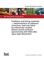
4.2.3.4c
Evaluation tests shall be performed as specified in Figure 4-1 and
Table 4-1.
New
4.2.3.4d
Omission of any of the elements of tests specified in Figure 4-1 and
Table 4-1, or the introduction of alternative activities, shall be
justified in the JD.
New
NOTE
4.2.3.4e
20
For mounting process (including baking
for PED), see ECSS-Q-ST-70-38 and ECSSQ-ST-70-08.
Evaluation of retinned components shall be performed as specified
in Figure 8-1 from the requirement 8.1a.
New
BS EN 16602-60-13:2015
EN 16602-60-13:2015 (E)
CLASS 1
EVALUATION
Evaluation (1)
5 parts
Construction
Analysis
10 parts
Electrical
characterization
@ 3 temperatures
10 parts (3)
10 parts (4)
10 parts
Electrical test
@ 25°C
10 parts
Electrical test
@ 3 temperatures
Electrical test
@ 25°C
Electrical test
@ 25°C
Seal test (5)
(fine & gross leak)
External visual
inspection
Seal test 5)
(fine & gross leak)
External visual
inspection
External visual
inspection
Preconditioning
External visual
inspection
Lifetest
2000h-125°C
Mechanical
shocks
HAST
96h-130°C-85%RH
(or THB 1000h)
C-SAM test (4)
Electrical test
@ 3 temperatures
Vibrations
Electrical test
@ 25°C
Preconditioning
(4)
External visual
inspection
Constant
acceleration
External visual
inspection
500 T/C
-55°C/+125°C
DPA
(3 parts)
Seal test (5)
(fine & gross leak)
Seal test (5)
(fine & gross leak)
Electrical test
@ 25°C
Electrical test
@ 25°C
External visual
inspection
External visual
inspection
(1) : for the evaluation of retinned components, see Figure 8-1
(2) : sampling and testing conditions in conformance with requirements
of ECSS-Q-ST-60-15
(3) : applicable in case of cavity package
(4) : applicable to plastic package only
(5) : applicable to hermetic & cavity package
sampling (2)
Radiation
Evaluation
C-SAM test (4)
Figure 4-1: Evaluation tests flow chart for Class 1 components
Table 4-1: Evaluation Tests for Class 1 components
TEST
1
2
Construction
analysis
Electrical
characterization
SAMPLING
5 parts
10 parts min
METHOD / CRITERIA
As per clause 4.2.2.3
See Annex H
Electrical test under 3 T° (min,
typ, max) or at using range +10
°C (whichever is higher as per
4.2.2.6).
COMMENTS
Read & record for
electrical test as per
the preliminary issue
of
the
internal
supplier’s
specification
(see
4.2.3.1.k).
21
BS EN 16602-60-13:2015
EN 16602-60-13:2015 (E)
TEST
3
External
inspection
SAMPLING
visual
10 parts min
ESCC 2055000
ESCC 2059000
MIL-STD-750 TM 2016, 1500g,
0,5ms duration - 50 shocks
instead of 5 shocks, planes X1,
Y1 and Z1.
Vibrations
10 parts min
MIL-STD-883,
TM
2007
condition A - 120 times (total)
instead of 12 times (total) MILSTD-750, TM 2056, 20g, 102000Hz, cross over at 50Hz 120 times (total) instead of 12
times (total).
MIL-STD-883,
TM
2001
condition
E
(resultant
centrifugal acceleration to be
in the Y1 axis only).
Preconditioning
6
+ 96h HAST (or
1000h THB 85/85)
C-SAM
Applicable to cavity
package.
Read & record for
electrical test as per
the preliminary issue
of
the
internal
supplier’s
specification
(see
4.2.3.1.k).
For components which have a
package weight of 5 grammes
or more, or whose inner seal or
cavity perimeter is more than 5
cm, Condition D shall be used
MIL-STD-750,
TM
2006,
20000g, planes X1, Y1 and Y2.
Constant
acceleration
5
COMMENTS
MIL STD 883 TM 2002
condition B - 50 pulses (per
orientation) instead of 5 pulses
(per orientation).
Mechanical shocks
4
METHOD / CRITERIA
10 parts min
10 parts min
HAST 96h-130°C-85% RH
(JESD22-A110 with continuous
bias) or THB (JESD22-A101)
Initial and final electrical test
at
25°C
(parameter
&
functional)
Preconditioning:
i.a.w. JESD-22-A113 for SMD
JESD-22-B106 for through hole.
JEDEC J-STD-020
Applicable to plastic
package.
Read & record for
electrical test as per
the preliminary issue
of
the
internal
supplier’s
specification
(see
4.2.3.1.k).
To be done on the 10
parts of step 7 after
the electrical test at
25°C
and
before
preconditioning.
C-SAM test only
applicable to plastic
package.
22
BS EN 16602-60-13:2015
EN 16602-60-13:2015 (E)
TEST
7
Preconditioning +
Thermal Cycling
SAMPLING
10 parts min
METHOD / CRITERIA
COMMENTS
500 T/C -55°/+125°C (or to the
manufacturer storage temp.,
whichever is less) MIL-STD750.
Preconditioning
applicable to plastic
package only.
method 1051 cond.B MIL-STD883 method 1010 cond.B
Initial, intermediate (100 T/C)
and final electrical tests at 25°C
(parameter & functional).
Preconditioning: i.a.w. JESD22-A113 for SMD JESD-22B106 for through hole.
MIL-STD-883
TM
1014
condition A or B (fine leak)
and condition C (gross leak).
8
Seal test
10 parts min
MIL-STD-750
TM
1071
condition H1 or H2 (fine leak)
and condition C or K (gross
leak with cavity) or condition
E (gross leak without cavity).
Read & record for
electrical tests as per
the preliminary issue
of
the
internal
supplier’s
specification
(see
4.2.3.1.k).
Applicable
hermetic &
package.
to
cavity
The lifetest duration
shall be 2000h at
minimum 125°C.
MIL-STD-750 method 1026 &
1042
9
Lifetest
2000h125°C minimum
10
DPA
11
Radiation
evaluation
10 parts min
MIL-STD-883
cond.D
method
1005
Initial, intermediate (1000h)
and final electrical tests at 3 T°
(min, typ, max) (parameter &
functional).
In
case
of
a
temperature
lower
than
125°C,
the
lifetest duration is
extended i.a.w. MILSTD-883
method
1005.
Read & record for
electrical tests. as per
the preliminary issue
of
the
internal
supplier’s
specification
(see
4.2.3.1.k).
3 parts
As per clause 4.3.9 see Annex
H.
To be done on 3 parts
after lifetest (as per
above step 4).
i.a.w. ECSS-QST-60-15
See ECSS-Q-ST-60-15
-
23