Bsi bs en 31092 1994 (1999)
Bạn đang xem bản rút gọn của tài liệu. Xem và tải ngay bản đầy đủ của tài liệu tại đây (491.09 KB, 18 trang )
BRITISH STANDARD
Textiles —
Determination of
physiological
properties —
Measurement of
thermal and
water-vapour
resistance under
steady-state conditions
(sweating
guarded-hotplate test)
The European Standard EN 31092:1993 has the status of a
British Standard
UDC 677.074/.077:620.1:677.017.87
BS EN
31092:1994
ISO 11092:
1993
BS EN 31092:1994
Cooperating organizations
The European Committee for Standardization (CEN), under whose supervision
this European Standard was prepared, comprises the national standards
organizations of the following countries:
Austria
Belgium
Denmark
Finland
France
Germany
Greece
Iceland
Ireland
Italy
Luxembourg
Netherlands
Norway
Portugal
Spain
Sweden
Switzerland
United Kingdom
Oesterreichisches Normungsinstitut
Institut belge de normalisation
Dansk Standardiseringsraad
Suomen Standardisoimisliito, r.y.
Association franỗaise de normalisation
Deutsches Institut fỹr Normung e.V.
Hellenic Organization for Standardization
Technological Institute of Iceland
National Standards Authority of Ireland
Ente Nazionale Italiano di Unificazione
Inspection du Travail et des Mines
Nederlands Normalisatie-instituut
Norges Standardiseringsforbund
Instituto Portugs da Qualidade
Asociación Espola de Normalización y Certificación
Standardiseringskommissionen i Sverige
Association suisse de normalisation
British Standards Institution
This British Standard, having
been prepared under the
direction of the Textiles and
Clothing Standards Policy
Committee, was published
under the authority of the
Standards Board and comes
into effect on
15 March 1994
Amendments issued since publication
© BSI 04-1999
Amd. No.
The following BSI references
relate to the work on this
standard:
Committee reference TCM/24
Draft for comment 90/46668 DC
ISBN 0 580 21444 3
Date
Comments
BS EN 31092:1994
Contents
Page
Cooperating organizations
Inside front cover
National foreword
ii
Foreword
2
Introduction
3
1
Scope
3
2
Definitions
3
3
Symbols and units
4
4
Principle
4
5
Apparatus
5
6
Test specimens
7
7
Test procedure
8
8
Precision of results
10
9
Test report
10
Annex A (normative) Mounting procedure for specimens
containing loose filling materials or having uneven thickness
11
Annex B (normative) Determination of correction terms
for heating power
11
Figure 1 — Measuring unit with temperature and water
supply control
5
Figure 2 — Thermal guard with temperature control
6
Figure 3 — Corrections for thermal edge losses during the measurement of
thermal resistance
7
National annex NA (informative) Committees responsible
Inside back cover
© BSI 04-1999
i
BS EN 31092:1994
National foreword
This British Standard has been prepared under the direction of the Textiles and
Clothing Standards Policy Committee and is the English language version of
EN 31092:1993 Textiles — Determination of physiological properties —
Measurement of thermal and water-vapour resistance under steady-state
conditions (sweating guarded-hotplate test), published by the European
Committee for Standardization (CEN). It is identical with ISO 11092:1993
published by the International Organization for Standardization (ISO).
A British Standard does not purport to include all the necessary provisions of a
contract. Users of British Standards are responsible for their correct application.
Compliance with a British Standard does not of itself confer immunity
from legal obligations.
Summary of pages
This document comprises a front cover, an inside front cover, pages i and ii,
the EN title page, pages 2 to 12, an inside back cover and a back cover
This standard has been updated (see copyright date) and may have had
amendments incorporated. This will be indicated in the amendment table on
the inside front cover.
ii
© BSI 04-1999
EUROPEAN STANDARD
EN 31092
NORME EUROPÉENNE
December 1993
EUROPÄISCHE NORM
UDC 677.074/.077:620.1:677.017.87
Descriptors: Textiles, woven fabrics, physiological properties, thermal comfort, measurement, thermal resistance, water vapour tests
English version
Textiles — Determination of physiological properties —
Measurement of thermal and water-vapour resistance
under steady-state conditions
(sweating guarded-hotplate test)
(ISO 11092:1993)
Textiles — Détermination des propriétés
physiologiques — Mesure des résistances
thermiques et évaporatives en régime
stationnaire (essai de la plaque chaude
transpirante gardée)
(ISO 11092:1993)
Textilien — Prüfung
bekleidungsphysiologischer Eigenschaften —
Prüfung des Wärme- und
Wasserdampfdurchgangs widerstandes unter
stationären Bedingungen (sweating
guarded-hotplate test)
(ISO 11092:1993)
www.bzfxw.com
This European Standard was approved by CEN on 1993-12-16. CEN members
are bound to comply with the CEN/CENELEC Internal Regulations which
stipulate the conditions for giving this European Standard the status of a
national standard without any alteration.
Up-to-date lists and bibliographical references concerning such national
standards may be obtained on application to the Central Secretariat or to any
CEN member.
This European Standard exists in three official versions (English, French,
German). A version in any other language made by translation under the
responsibility of a CEN member into its own language and notified to the
Central Secretariat has the same status as the official versions.
CEN members are the national standards bodies of Austria, Belgium,
Denmark, Finland, France, Germany, Greece, Iceland, Ireland, Italy,
Luxembourg, Netherlands, Norway, Portugal, Spain, Sweden, Switzerland and
United Kingdom.
CEN
European Committee for Standardization
Comité Européen de Normalisation
Europäisches Komitee für Normung
Central Secretariat: rue de Stassart 36, B-1050 Brussels
© 1993 Copyright reserved to CEN members
Ref. No. EN 31092:1993 E
EN 31092:1993
Foreword
This European Standard is the endorsement of
ISO 11092. Endorsement of ISO 11092 was
recommended by CEN/TC 248 “Textiles and textile
products” under whose competence this European
Standard will henceforth fail.
This European Standard shall be given the status of
a national standard, either by publication of an
identical text or by endorsement, at the latest by
June 1994, and conflicting national standards shall
be withdrawn by June 1994.
The standard was approved and in accordance with
the CEN/CENELEC Internal Regulations, the
following countries are bound to implement this
European Standard: Austria, Belgium, Denmark,
Finland, France, Germany, Greece, Iceland,
Ireland, Italy, Luxembourg, Netherlands, Norway,
Portugal, Spain, Sweden, Switzerland,
United Kingdom.
www.bzfxw.com
2
© BSI 04-1999
EN 31092:1993
Introduction
ISO 11092 is the first of a number of standard test
methods in the field of clothing comfort.
The physical properties of textile materials which
contribute to physiological comfort involve a
complex combination of heat and mass transfer.
Each may occur separately or simultaneously. They
are time-dependent, and may be considered in
steady-state or transient conditions.
Thermal resistance is the net result of the
combination of radiant, conductive and convective
heat transfer, and its value depends on the
contribution of each to the total heat transfer.
Although it is an intrinsic property of the textile
material, its measured value may change through
the conditions of test due to the interaction of
parameters such as radiant heat transfer with the
surroundings.
Several methods exist which may be used to
measure heat and moisture properties of textiles,
each of which is specific to one or the other and
relies on certain assumptions for its interpretation.
The sweating guarded-hotplate (often referred to as
the “skin model”) described in this International
Standard is intended to simulate the heat and mass
transfer processes which occur next to human skin.
Measurements involving one or both processes may
be carried out either separately or simultaneously
using a variety of environmental conditions,
involving combinations of temperature, relative
humidity, air speed, and in the liquid or gaseous
phase. Hence transport properties measured with
this apparatus can be made to simulate different
wear and environmental situations in both
transient and steady states. In this standard only
steady-state conditions are selected.
The test conditions used in this standard are not
intended to represent specific comfort situations,
and performance specifications in relation to
physiological comfort are not stated.
2 Definitions
For the purposes of this International Standard, the
following definitions apply.
2.1
thermal resistance, Rct
temperature difference between the two faces of a
material divided by the resultant heat flux per unit
area in the direction of the gradient. The dry heat
flux may consist of one or more conductive,
convective and radiant components
thermal resistance Rct, expressed in square metres
kelvin per watt, is a quantity specific to textile
materials or composites which determines the dry
heat flux across a given area in response to a steady
applied temperature gradient
2.2
water-vapour resistance, Ret
water-vapour pressure difference between the two
faces of a material divided by the resultant
evaporative heat flux per unit area in the direction
of the gradient. The evaporative heat flux may
consist of both diffusive and convective components.
water-vapour resistance Ret, expressed in square
metres pascal per watt, is a quantity specific to
textile materials or composites which determines
the “latent” evaporative heat flux across a given
area in response to a steady applied water-vapour
pressure gradient
www.bzfxw.com
1 Scope
This International Standard specifies methods for
the measurement of the thermal resistance and
water-vapour resistance, under steady-state
conditions, of e.g. fabrics, films, coatings, foams and
leather, including multilayer assemblies, for use in
clothing, quilts, sleeping bags, upholstery and
similar textile or textile-like products.
The application of this measurement technique is
restricted to a maximum thermal resistance and
water-vapour resistance which depend on the
dimensions and construction of the apparatus used
(e.g. 2 m2.K/W and 700 m2.Pa/W respectively, for
the minimum specifications of the equipment
referred to in this International Standard).
© BSI 04-1999
2.3
water-vapour permeability index, imt
ratio of thermal and water-vapour resistances in
accordance with equation (1):
R ct
i mt = S ⋅ -------R et
...(1)
where S equals 60 Pa/K
imt is dimensionless, and has values between 0
and 1. A value of 0 implies that the material is
water-vapour impermeable, that is, it has infinite
water-vapour resistance, and a material with a
value of 1 has both the thermal resistance and
water-vapour resistance of an air layer of the same
thickness
3
EN 31092:1993
2.4
water-vapour permeability, Wd
characteristic of a textile material or composite
depending on water-vapour resistance and
temperature in accordance with equation (2):
1
Wd = -------------------------R et ⋅ Ì
Tm
...(2)
where
ÌT
m
is the latent heat of vaporization of water
at the temperature Tm of the measuring
unit
equals, for example, 0,672 W·h/g at
Tm = 35 °C
Water-vapour permeability is expressed in grams
per square metre hour pascal
3 Symbols and units
Rct
Ret
imt
Rct0
is the thermal resistance, in square metres
kelvin per watt
is the water-vapour resistance, in square
metres pascal per watt
is the water-vapour permeability index,
dimensionless
is the apparatus constant, in square metres
kelvin per watt, for the measurement of
thermal resistance Rct
Ret0 is the apparatus constant, in square metres
pascal per watt, for the measurement of
water-vapour resistance Ret
Wd
ÌT
m
A
Ta
Tm
Ts
Pa
is the water-vapour permeability, in grams
per square meter hour pascal
is the latent heat of vaporization of water at
the temperature Tm, in watt hours per gram
is the area of the measuring unit, in square
metres
is the air temperature in the test enclosure,
in degrees Celsius
is the temperature of the measuring unit, in
degrees Celsius
is the temperature of the thermal guard, in
degrees Celsius
is the water-vapour partial pressure, in
pascals, of the air in the test enclosure at
temperature Ta
Pm
is the saturation water-vapour partial
pressure, in pascals, at the surface of the
measuring unit at temperature Tm
va
is the speed of air above the surface of the
test specimen, in metres per second
4
is the standard deviation of air speed va, in
metres per second
R.H. is the relative humidity, in percent
H
is the heating power supplied to the
measuring unit, in watts
%Hc is the correction term for heating power for
the measurement of thermal resistance Rct
sv
%He is the correction term for heating power for
the measurement of water-vapour resistance
Ret
µ
is the slope of the correction line for the
calculation of %Hc
is the slope of the correction line for the
calculation of %He
4 Principle
The specimen to be tested is placed on an electrically
heated plate with conditioned air ducted to flow
across and parallel to its upper surface as specified
in this International Standard.
For the determination of thermal resistance, the
heat flux through the test specimen is measured
after steady-state conditions have been reached.
The technique described in this International
Standard enables the thermal resistance Rct of a
material to be determined by subtracting the
thermal resistance of the boundary air layer above
the surface of the test apparatus from that of a test
specimen plus boundary air layer, both measured
under the same conditions.
For the determination of water-vapour resistance,
an electrically heated porous plate is covered by a
water-vapour permeable but liquid-water
impermeable membrane. Water fed to the heated
plate evaporates and passes through the membrane
as vapour, so that no liquid water contacts the test
specimen. With the test specimen placed on the
membrane, the heat flux required to maintain a
constant temperature at the plate is a measure of
the rate of water evaporation, and from this the
water-vapour resistance of the test specimen is
determined.
The technique described in this International
Standard enables the water-vapour resistance Ret of
a material to be determined by subtracting the
water-vapour resistance of the boundary air layer
above the surface of the test apparatus from that of
a test specimen plus boundary air layer, both
measured under the same conditions.
www.bzfxw.com
© BSI 04-1999
EN 31092:1993
5 Apparatus
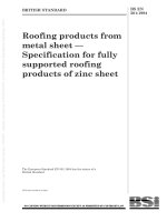
5.1 Measuring unit, with temperature and water
supply control, consisting of a metal plate
approximately 3 mm thick with a minimum area
of 0,04 m2 (e.g. a square with each side 200 mm in
length) fixed to a conductive metal block containing
an electrical heating element [see Figure 1,
items (1) and (6)]. For the measurement of
water-vapour resistance, the metal plate (1) must be
porous. It is surrounded by a thermal guard
[item (8) of Figure 2] which is in turn located within
an opening in a measuring table (11).
The coefficient of radiant emissivity of the plate
surface (1) shall be greater than 0,35, measured
at 20 °C between the wavelengths 8 4m to 14 4m,
with the primary beam perpendicular to the plate
surface and the reflection hemispherical.
Channels are machined into the face of the heating
element block (6) where it contacts the porous plate
to enable water to be fed from a dosing device (5).
The position of the measuring unit with respect to
the measuring table shall be adjustable, so that the
upper surface of test specimens placed on it can be
made coplanar with the measuring table.
Heat losses from the wiring to the measuring unit or
to its temperature-measuring device should be
minimized, e.g. by leading as much wiring as
possible along the inner face of the thermal
guard (8).
The temperature controller (3), including the
temperature sensor of the measuring unit (2), shall
maintain the temperature Tm of the measuring
unit (7) constant to within ± 0,1 K. The heating
power H shall be measurable by means of a suitable
device (4) to within ± 2 % over the whole of its usable
range.
Water is supplied to the surface of the porous metal
plate (1) by a dosing device (5) such as a
motor-driven burette. The dosing device is activated
by a switch which senses when the level of water in
the plate falls more than approximately 1,0 mm
below the plate surface, in order to maintain a
constant rate of evaporation. The level switch is
mechanically connected to the measuring unit.
Before entering the measuring unit, the water shall
be preheated to the temperature of the measuring
unit. This can be achieved by passing it through
tubes in the thermal guard before it enters the
measuring unit.
www.bzfxw.com
Figure 1 — Measuring unit with temperature and water supply control
© BSI 04-1999
5
EN 31092:1993
www.bzfxw.com
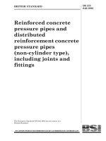
Figure 2 — Thermal guard with temperature control
5.2 Thermal guard with temperature control
[item (8) of Figure 2], consisting of a material with
high thermal conductivity, typically metal, and
containing electrical heating elements.
Its purpose is to prevent heat leakage from the sides
and bottom of the measuring unit (7).
The width b of the thermal guard (Figure 2) should
be a minimum of 15 mm. The gap between the upper
surface of the thermal guard and the metal plate of
the measuring unit shall not exceed 1,5 mm.
The thermal guard may be fitted with a porous plate
and water-dosing system similar to that of the
measuring unit to form a moisture guard.
The thermal guard temperature Ts measured by the
temperature sensor (10) shall, by means of the
controller (9), be maintained at the same
temperature as the measuring unit Tm to
within ± 0,1 K.
5.3 Test enclosure, into which is built the measuring
unit and thermal guard, and in which the ambient
air temperature and humidity are controlled.
6
The conditioned air shall be ducted so that it flows
across and parallel to the upper surface of the
measuring unit and thermal guard. The height of
the duct above the measuring table shall not be less
than 50 mm.
The drift of the temperature Ta of this air flow shall
not exceed ± 0,1 K for the duration of a test. For the
measurement of thermal resistance, and
water-vapour resistance values below 100 m2·Pa/W,
an accuracy of ± 0,5 K is sufficient.
The drift of the relative humidity R.H. of this air
flow shall not exceed ± 3 % R.H. for the duration of
a test.
This air flow is measured at a point 15 mm above
the measuring table over the centre of the
uncovered measuring unit and at an air
temperature Ta of 20 °C. The air speed va measured
at this point shall have a mean value of 1 m/s, with
the drift not exceeding ± 0,05 m/s for the duration of
a test.
© BSI 04-1999
EN 31092:1993
www.bzfxw.com
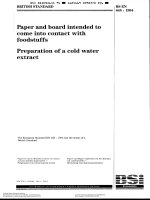
Figure 3 — Corrections for thermal edge losses during the measurement of
thermal resistance
It is important that at this point the air flow shall
have a certain degree of turbulence, expressed by
the related variation in air speed sv/va, of
between 0,05 and 0,1, measured at
approximately 6 s intervals over a time period of
at least 10 min with an instrument which has a
time constant of less than 1 s.
6 Test specimens
6.1 Materials < 5 mm thick
Test specimens shall completely cover the surfaces
of the measuring unit and thermal guard.
From each material to be tested, a minimum of
three test specimens shall be cut and tested.
Before testing, specimens shall be conditioned for a
minimum of 12 h at the temperature and humidity
specified in either 7.3 or 7.4 as appropriate.
6.2 Materials > 5 mm thick
6.2.1 Specimens falling into this category require a
special test procedure to avoid loss of heat or water
vapour from their edges.
© BSI 04-1999
In the measurement of thermal resistance,
corrections for thermal edge losses are necessary if
the specimen thickness is greater than
approximately twice the width b of the thermal
guard (see Figure 2). The deviation from the linear
relationship between thermal resistance and
specimen thickness can be determined and
corrected by the factor [1 + (%Rct/Rct measured)] using
the measurement of the Rct values for several
thicknesses of a homogeneous material such as
foam, up to a total thickness d of at least that of the
specimen to be tested (see Figure 3).
6.2.2 If the thermal guard is not fitted with a porous
plate and water-dosing system similar to that of the
measuring unit, for the measurement of
water-vapour resistance the vertical sides of the cut
specimens shall be surrounded by a water-vapour
impermeable frame of approximately the same
height as that of the free-standing specimen. The
inner dimensions of the frame shall be the same on
all sides as those of the porous plate of the
measuring unit.
7
EN 31092:1993
6.2.3 Before testing, specimens shall be conditioned
for a minimum of 24 h at the temperature and
humidity specified in either 7.3 or 7.4 as
appropriate.
6.2.4 Specimens containing loose filling materials or
having uneven thickness, such as quilts and
sleeping bags, require a special mounting procedure
as described in Annex A.
7 Test procedure
7.1 Determination of apparatus constants
In the values for thermal and water-vapour
resistance measured with the device described in
this International Standard, constants intrinsic to
the apparatus are included. These constants
comprise the resistance within the measuring unit
itself, plus that of the boundary air layer adhering to
the surface of the test specimen. The latter is
dependent on the speed and degree of turbulence of
the air flowing over the test specimen.
These apparatus constants, Rct0 and Ret0, are
determined as “bare plate” values, and it is essential
that the upper surface of the measuring unit is
coplanar with the measuring table.
7.1.1 Determination of Rct0
For the determination of Rct0 set the temperature of
the measuring unit Tm at 35 °C and the air
temperature Ta at 20 °C with a relative humidity
R.H. of 65 %. Set the air speed va to 1 m/s. Any
deviations from these values shall be within the
limits stated in clause 5. Wait until the measured
quantities (Tm, Ta, R.H., H) reach steady-state
before recording their values.
The bare plate resistance Rct0 is determined from
equation (3).
( Tm – Ta ) ⋅ A
R ct0 = ---------------------------------H – %H c
...(3)
%Hc is a correction term and is determined as
described in Annex B.
7.1.2 Determination of Ret0
7.1.2.1 During the determination of Ret0, the
surface of the porous plate is kept constantly moist
by means of a water-dosing device (see 5.1). A
smooth, water-vapour permeable but liquid-water
impermeable cellophane membrane of
thickness 10 4m – 50 4m shall be fitted over the
porous plate.
1)
The cellophane membrane shall be moistened with
distilled water and fixed to the measuring plate by
appropriate means so that it remains completely
free of wrinkles.
The water supplied to the measuring plate shall be
distilled, preferably double-distilled, and reboiled
prior to use so that it is free of gas in order to
prevent the formation of gas bubbles beneath the
membrane.
7.1.2.2 Set the temperature of both the measuring
unit Tm and the air temperature Ta at 35 °C. Set the
air speed va to 1 m/s.
The relative humidity R.H. of the air shall be kept
constant at 40 %, corresponding to a water-vapour
partial pressure pa of 2 250 Pa. The water-vapour
partial pressure pm directly at the surface of the
measuring unit can be assumed equal to the
saturation vapour pressure at the temperature of
this surface, i.e. 5 620 Pa, without compromising
the accuracy of the test.
Any deviations from the above values of Tm, Ta, va
and R.H. shall be within the limits stated in
clause 5. Wait until the measured quantities
(Tm, Ta, R.H., H) reach steady-state before
recording their values.
7.1.2.3 The bare plate resistance Ret0 is determined
from equation (4).
www.bzfxw.com
( p m – pa ) ⋅ A
R et0 = --------------------------------H – %H e
...(4)
%He is a correction term and is determined as
described in Annex B.
7.1.3 Reference material
A useful cross-check of the apparatus can be
obtained by measuring a precalibrated thermal
resistance material, e.g. a reference material for
thermal conductivity1).
7.1.4 Recalibration
Check the apparatus constants Rct0 and Ret0 at
regular intervals. Where deviations greater than
the accuracy of the measuring device occur
(see clause 8), an adjustment shall be made. In most
cases a change in Rct0 or Ret0 is caused by a
deviation in the speed of the air va over the surface
of the test specimen. Air speed should be checked at
regular intervals by the technique described in 5.3.
Obtainable from the Community Bureau of Reference, Rue de la Loi 2000, B-1049 Brussels, Belgium; Order No. CRM 064 A
(dimensions 300 mm × 300 mm, thickness 33,5 mm, density 90.9 kg/m3, thermal resistance Rct = 1,092 ± 0,015 m2·K/W).
8
© BSI 04-1999
EN 31092:1993
The air flow (both speed and degree of turbulence)
over the surface of the test specimen influences the
resistance of the boundary layer which adheres to
the outer surface of the specimen, and thus
influences the test result.
7.2 Assembly of test specimens on the
measuring unit
7.2.1 Where appropriate, the orientation of the test
specimens with respect to the air flow shall be
defined and described in the test report.
The test specimens shall be placed so that they lie
flat across the measuring unit, with the side
normally facing the human body towards the
measuring unit. In the case of multiple layers,
specimens shall be arranged and stacked on the
measuring unit as on the human body.
Water-vapour impermeable adhesive tape or a light
metal frame may be used around the edges of the
test specimen to keep it flat.
Bubbles and wrinkles in the test specimen, or air
gaps between the specimen and measuring unit or
between the components of multilayer specimens,
shall be prevented provided they are not specific to
the surface profile of the specimens.
7.2.2 Normally, test specimens are measured free
from stretch or loading and, in the case of multiple
layers, without air gaps between layers. However, if
a test is carried out under extension or applied
pressure or with air gaps, this shall be mentioned in
the test report.
7.2.3 With test specimens thicker than 3 mm, the
measuring unit shall be lowered so that the outer
surface of the specimen is flush with the measuring
table.
7.3.2 Calculate the thermal resistance Rct from
equation (5):
( Tm – Ta ) ⋅ A
R ct = ---------------------------------- – R ct0
H – %H c
...(5)
where the symbols and units are defined in clause 3.
Calculate the thermal resistance Rct of the material
being tested as the arithmetic mean of the
individual measurements.
7.4 Measurement of water-vapour
resistance Ret
7.4.1 For the measurement of water-vapour
resistance, a water-vapour permeable but
liquid-water impermeable cellophane membrane
shall be fitted over the surface of the measuring unit
as described in 7.1.2.
7.4.2 Set the temperature of both the measuring
unit Tm and the air Ta to 35 °C with a relative
humidity R.H. of 40 %. Hold the air speed va
at 1 m/s. Any deviations from these values shall be
within the limits stated in clause 5.
These isothermal conditions prevent water-vapour
condensation within the test specimen.
Other conditions of relative humidity and air speed
va may be used. The test report shall describe the
alternative conditions and shall include a statement
to the effect that the results may differ from those of
tests carried out under the conditions stated in this
International Standard.
If the air temperature Ta is changed, the test is
non-isothermal and this International Standard no
longer applies.
After placing the test specimen on the measuring
unit, wait until the measured quantities (Tm, Ta,
R.H., H) have reached steady-state before recording
their values.
7.4.3 Calculate the water-vapour resistance Ret
from equation (8):
www.bzfxw.com
7.3 Measurement of thermal resistance Rct
7.3.1 Set the temperature of the measuring unit Tm
at 35 °C and the air temperature Ta at 20 °C with a
relative humidity R.H. of 65 %. Set the air speed va
at 1 m/s. Any deviations from these values shall be
within the limits stated in clause 5.
Other conditions of air temperature Ta, relative
humidity R.H. and air speed va may be used. The
test report shall describe the alternative conditions
and shall include a statement to the effect that the
results differ from those of tests carried out under
the conditions stated in this International
Standard.
After placing the test specimen on the measuring
unit, wait until the measured quantities (Tm, Ta,
R.H., H) reach steady-state before recording their
values.
© BSI 04-1999
( pm – pa ) ⋅ A
R et = --------------------------------- – R et0
H – %H e
...(6)
where the symbols and units are defined in clause 3.
Calculate the water-vapour resistance Ret of the
material being tested as the arithmetic mean of the
individual measurements.
9
EN 31092:1993
8 Precision of results
9 Test report
8.1 Repeatability
The test report shall include at least the following
information:
a) reference to this International Standard;
b) complete description of the material to be
tested;
c) arrangement of test specimens according
to 7.2;
d) number of test specimens per material to be
tested and number of individual measurements
on each test specimen;
e) test climate;
f) arithmetic mean value of the thermal
resistance; and/or
g) arithmetic mean value of the water-vapour
resistance;
h) details of deviations from this International
Standard;
i) date of test.
For thermal resistance Rct, the precision of repeated
measurements on the same specimens with values
up to 50 × 10–3 m2·K/W has been found to
be 3,0 × 10⁻³ m2·K/W, as measured on single layers
of fabrics. With Rct values higher
than 50 × 10–3 m2·K/W, the precision has been found
to be 7 %, as measured on foams.
For water-vapour resistance Ret, the precision of
repeated measurements on the same specimens
with values up to 10 m2·Pa/W has been found to
be 0,3 m2.Pa/W, as measured on single layers of
fabrics.
With Ret values higher than 10 m2.pa/W, the
precision has been found to be 7 %, as measured on
foams.
8.2 Reproducibility
In an interlaboratory trial using three specimens of
a foam material of 3 mm, 6 mm and 12 mm
thickness tested in four laboratories, an average
standard deviation of 6,5 × 10⁻³ m2·K/W for thermal
resistance Rct and of 0,67 m2·Pa/W for water-vapour
resistance Ret was found.
10
www.bzfxw.com
© BSI 04-1999
EN 31092:1993
Annex A (normative)
Mounting procedure for specimens
containing loose filling materials or
having uneven thickness
A.1 For samples containing loose filling materials or
having uneven thickness, such as quilts and
sleeping bags, a minimum of three test specimens
shall be cut if possible. If not possible, the actual
number of specimens tested shall be noted in the
test report. With material composites such as quilts
and sleeping bags which are of uneven thickness
due to quilting, a minimum of two test specimens
each are prepared for the measurement of thermal
and water-vapour resistance.
A.2 These specimens shall be placed into frames of
approximately the same height as that of the
free-standing specimen.
For the measurement of thermal resistance Rct, the
inner dimensions of these frames shall be at least
(l + 2b) (see Figure 1 and Figure 2).
For the measurement of water-vapour resistance
Ret, the inner dimensions of the frames shall be the
same on all sides as those of the porous plate of the
measuring unit.
A.3 Select the two specimens so that one has the
maximum possible number of quiltings and the
other the minimum possible number of quiltings
located in their central areas.
B.2 The correction term for heating power %Hc is
linearly related to the difference in temperature
between measuring unit and thermal guard, as
given by equation (B.1).
%H c = µ ( T m – T s )
...(B.1)
The slope µ is determined as follows.
The measuring unit and thermal guard are covered
with a material of high thermal insulation (e.g. foam
with a thickness of 4 cm min.). The air temperature
is set to 20 °C, with the temperature of the
measuring unit at 35 °C. The temperature
controller of the thermal guard is used to vary the
guard temperature between 34 °C and 36 °C in steps
of 0,2 K. After steady-state is reached at each
setting, the heating power supplied to the
measuring unit is recorded. A linear regression of
this heating power versus the difference in
temperature between measuring unit and thermal
guard gives a straight line with slope µ.
B.3 The correction term for heating power %He, is
determined as given by equation (B.2).
%H e = ¶ ( T m – T s )
... (B.2)
www.bzfxw.com
Annex B (normative)
Determination of correction terms for
heating power
B.1 During the measurement of thermal resistance
and water-vapour resistance, the temperatures of
the measuring unit and the thermal guard are set to
the same value. However, the tolerances stated
in 5.1 and 5.2 in practice may cause slight
differences in temperature between measuring unit
and thermal guard, in such cases the heating power
supplied to the measuring unit does not equal the
heat flux through the test specimen. This shall be
taken into account by the application of correction
terms %Hc or %He for the heating power in the
measurement of thermal resistance or water-vapour
resistance, respectively.
â BSI 04-1999
The slope ả is determined as follows.
The measuring unit is covered by a water-vapour
permeable membrane as described in 6.1.2 and
supplied with water by the dosing device. The
measuring unit and thermal guard are covered by a
water-vapour impermeable material
[e.g. polyethylene terephthalate (PET) film] and a
material of high thermal insulation (e.g. foam with
a thickness of 4 cm min.). The air temperature is set
to 35 °C with a relative humidity R.H. of 40 %, and
the temperature of the thermal guard is set to 35 °C.
The temperature of the measuring unit is raised
relative to the thermal guard in steps of 0,2 K. After
steady-state is reached at each setting, the heating
power supplied to the measuring unit is recorded.
The regression line of this heating power versus the
difference in temperature between measuring unit
and thermal guard gives the slope ả.
B.4 The slopes à and ả for the correction terms for
heating power shall be checked after changes or
repairs to the apparatus.
11
www.bzfxw.com
12
blank
BS EN 31092:1994
National annex NA (informative)
Committees responsible
The United Kingdom participation in the preparation of this European Standard was entrusted by the
Textiles and Clothing Standards Policy Committee (TCM/-) to Technical Committee TCM/24 upon which
the following bodies were represented:
Association of Consulting Scientists
British Nonwovens Manufacturers’ Association
British Polyolefin Textiles Association
British Textile Confederation
British Textile Machinery Association
British Textile Technology Group
British Throwsters’ Association
Confederation of British Wool Textiles Ltd.
Furniture Industry Research Association
International Wool Secretariat
Ministry of Defence
National Wool Textile Export Corporation
SATRA Footwear Technology Centre
Soap and Detergent Industry Association
Society of Dyers and Colourists
Textile Finishers’ Association
Textile Institute
www.bzfxw.com
© BSI 04-1999
BS EN
31092:1994
ISO 11092:
1993
BSI — British Standards Institution
BSI is the independent national body responsible for preparing
British Standards. It presents the UK view on standards in Europe and at the
international level. It is incorporated by Royal Charter.
Revisions
British Standards are updated by amendment or revision. Users of
British Standards should make sure that they possess the latest amendments or
editions.
It is the constant aim of BSI to improve the quality of our products and services.
We would be grateful if anyone finding an inaccuracy or ambiguity while using
this British Standard would inform the Secretary of the technical committee
responsible, the identity of which can be found on the inside front cover.
Tel: 020 8996 9000. Fax: 020 8996 7400.
BSI offers members an individual updating service called PLUS which ensures
that subscribers automatically receive the latest editions of standards.
Buying standards
Orders for all BSI, international and foreign standards publications should be
addressed to Customer Services. Tel: 020 8996 9001. Fax: 020 8996 7001.
In response to orders for international standards, it is BSI policy to supply the
BSI implementation of those that have been published as British Standards,
unless otherwise requested.
Information on standards
www.bzfxw.com
BSI provides a wide range of information on national, European and
international standards through its Library and its Technical Help to Exporters
Service. Various BSI electronic information services are also available which give
details on all its products and services. Contact the Information Centre.
Tel: 020 8996 7111. Fax: 020 8996 7048.
Subscribing members of BSI are kept up to date with standards developments
and receive substantial discounts on the purchase price of standards. For details
of these and other benefits contact Membership Administration.
Tel: 020 8996 7002. Fax: 020 8996 7001.
Copyright
Copyright subsists in all BSI publications. BSI also holds the copyright, in the
UK, of the publications of the internationalstandardization bodies. Except as
permitted under the Copyright, Designs and Patents Act 1988 no extract may be
reproduced, stored in a retrieval system or transmitted in any form or by any
means – electronic, photocopying, recording or otherwise – without prior written
permission from BSI.
This does not preclude the free use, in the course of implementing the standard,
of necessary details such as symbols, and size, type or grade designations. If these
details are to be used for any other purpose than implementation then the prior
written permission of BSI must be obtained.
BSI
389 Chiswick High Road
London
W4 4AL
If permission is granted, the terms may include royalty payments or a licensing
agreement. Details and advice can be obtained from the Copyright Manager.
Tel: 020 8996 7070.