Bsi bs en 50085 2 1 2006 + a1 2011
Bạn đang xem bản rút gọn của tài liệu. Xem và tải ngay bản đầy đủ của tài liệu tại đây (836.4 KB, 28 trang )
BRITISH STANDARD
BS EN
50085-2-1:2006
+A1:2011
Incorporating
corrigendum
August 2007
Cable trunking systems
and cable ducting
systems for electrical
installations —
Part 2-1: Cable trunking systems and
cable ducting systems intended for
mounting on walls and ceilings
ICS 29.120.10
BS EN 50085-2-1:2006+A1:2011
National foreword
This British Standard is the UK implementation of
EN 50085-2-1:2006+A1:2011. It supersedes BS EN 50085-2-1:2006,
which is withdrawn.
The start and finish of text introduced or altered by amendment is
indicated in the text by tags. Tags indicating changes to CENELEC text
carry the number of the CENELEC amendment. For example, text
altered by CENELEC amendment A1 is indicated by !".
The UK participation in its preparation was entrusted to Technical
Committee PEL/213, Cable management.
A list of organizations represented on this committee can be obtained on
request to its secretary.
This publication does not purport to include all the necessary provisions
of a contract. Users are responsible for its correct application.
Compliance with a British Standard cannot confer immunity
from legal obligations.
This British Standard was
published under the authority
of the Standards Policy and
Strategy Committee
on 30 November 2006
© BSI 2011
ISBN 978 0 580 70916 6
Amendments/corrigenda issued since publication
Date
Comments
31 August 2007
Addition of supersession details
30 November 2011
Implementation of CENELEC amendment A1:2011
EUROPEAN STANDARD
EN 50085-2-1:2006+A1
NORME EUROPÉENNE
EUROPÄISCHE NORM
October 2011
ICS 29.120.10
English version
Cable trunking systems and cable ducting systems
for electrical installations
Part 2-1: Cable trunking systems and cable ducting systems
intended for mounting on walls and ceilings
Systèmes de goulottes et systèmes
de conduits-profilés pour installations
électriques
Partie 2-1: Systèmes de goulottes et
systèmes de conduits-profilés prévus pour
être montés sur les murs et les plafonds
Elektroinstallationskanalsysteme
für elektrische Installationen
Teil 2-1: Besondere Anforderungen
für Elektroinstallationskanalsysteme
für Wand und Decke
This European Standard was approved by CENELEC on 2006-10-01. CENELEC members are bound to comply
with the CEN/CENELEC Internal Regulations which stipulate the conditions for giving this European Standard
the status of a national standard without any alteration.
Up-to-date lists and bibliographical references concerning such national standards may be obtained on
application to the Central Secretariat or to any CENELEC member.
This European Standard exists in three official versions (English, French, German). A version in any other
language made by translation under the responsibility of a CENELEC member into its own language and notified
to the Central Secretariat has the same status as the official versions.
CENELEC members are the national electrotechnical committees of Austria, Belgium, Cyprus, the Czech
Republic, Denmark, Estonia, Finland, France, Germany, Greece, Hungary, Iceland, Ireland, Italy, Latvia,
Lithuania, Luxembourg, Malta, the Netherlands, Norway, Poland, Portugal, Romania, Slovakia, Slovenia, Spain,
Sweden, Switzerland and the United Kingdom.
CENELEC
European Committee for Electrotechnical Standardization
Comité Européen de Normalisation Electrotechnique
Europäisches Komitee für Elektrotechnische Normung
Central Secretariat: rue de Stassart 35, B - 1050 Brussels
© 2006 CENELEC -
All rights of exploitation in any form and by any means reserved worldwide for CENELEC members.
Ref. No. EN 50085-2-1:2006 E
BS EN 50085-2-1:2006+A1:2011
EN 50085-2-1:2006+A1:2011 (E)
–2–
Foreword
This European Standard was prepared by the Technical Committee CENELEC TC 213, Cable
management.
The text of the draft was submitted to the formal vote and was approved by CENELEC as EN 50085-2-1
on 2006-10-01.
The following dates were fixed:
– latest date by which the EN has to be implemented
at national level by publication of an identical
national standard or by endorsement
(dop)
2007-10-01
– latest date by which the national standards conflicting
with the EN have to be withdrawn
(dow)
2009-10-01
This standard is a system standard for cable management products used for electro-technical
purposes. It relates to the Council Directives on the approximation of laws, regulations and
administrative provisions of the Member States relating to Low Voltage Directive (73/23/EEC)
through consideration of the essential requirements of this directive.
This standard is supported by separate standards to which references are made.
This Part 2 is to be used in conjunction with EN 50085-1:2005, Cable trunking and cable ducting
systems for electrical installations – Part 1: General requirements.
This Part 2 supplements or modifies the corresponding clauses of Part 1. Where a particular
clause or subclause of Part 1 is not mentioned in this Part 2, that clause or subclause of Part 1
applies as far as is reasonable. Where this Part 2 states “addition” or “replacement”, the relevant
text of Part 1 is to be adapted accordingly.
Subclauses and figures which are additional to those in Part 1 are numbered starting from 101.
Foreword to amendment A1
This document (EN 50085-2-1:2006/A1:2011) has been prepared by the Technical Committee
CENELEC TC 213, "Cable management systems".
The following dates are fixed:
• latest date by which this document has to
be implemented at national level by
publication of an identical national
standard or by endorsement
• latest date by which the national standards
conflicting with this
document have to be withdrawn
(dop)
2012-10-10
(dow)
2014-10-10
Attention is drawn to the possibility that some of the elements of this document may be the
subject of patent rights. CENELEC [and/or CEN] shall not be held responsible for identifying any
or all such patent rights.
__________
–3–
BS EN 50085-2-1:2006+A1:2011
EN 50085-2-1:2006+A1:2011 (E)
Contents
Page
1
Scope ...............................................................................................................................4
2
Normative references........................................................................................................4
3
Definitions ........................................................................................................................4
4
General requirements .......................................................................................................5
5
General conditions for tests ..............................................................................................5
6
Classification ....................................................................................................................5
7
Marking and documentation ..............................................................................................7
8
Dimensions.......................................................................................................................7
9
Construction .....................................................................................................................7
10 Mechanical properties .......................................................................................................9
11 Electrical properties ........................................................................................................ 14
12 Thermal properties ......................................................................................................... 14
13 Fire effects ..................................................................................................................... 14
14 External influences ......................................................................................................... 14
15 Electromagnetic compatibility .......................................................................................... 14
Annex A (informative) Types of cable trunking systems (CTS) and cable ducting systems
(CDS) ................................................................................................. 24
Annex B (informative)............................................................................................................ 24
Annex C (normative) ............................................................................................................. 24
Figure 101 - Types and application of CTS/CDS for wall or ceiling installation ........................ 15
Figure 102 - Arrangement for cable support test according to 10.2.2 ...................................... 16
Figure 103 - Arrangement for cable support test according to 10.2.3 ...................................... 16
Figure 104 - Arrangement for cable support test according to 10.2.4 ...................................... 17
Figure 105 - Arrangement for cable support test according to 10.2.5 ...................................... 17
Figure 106 - Impact test for installation and application – Principles for arrangement ............. 18
Figure 107 - Impact test for installation and application – Examples for arrangement ............. 21
Figure 108 - Arrangement for linear deflection test ................................................................ 22
Figure 109 - Example of arrangement for CDS compression test ........................................... 23
BS EN 50085-2-1:2006+A1:2011
EN 50085-2-1:2006+A1:2011 (E)
1
–4–
Scope
Replacement:
This European Standard specifies requirements and tests for cable trunking systems (CTS) and
cable ducting systems (CDS) intended for the accommodation, and where necessary for the
electrically protective separation, of insulated conductors, cables and possibly other electrical
equipment in electrical and/or communication systems installations. The maximum voltage of these
installations is 1 000 V a.c. and 1 500 V d.c.
These systems are intended for mounting on walls and/or ceilings. They may be embedded,
installed in a flush or semi-flush state, surface mounted or mounted away from the surface using
fixing devices.
This standard does not apply to conduit systems, cable tray systems, cable ladder systems, power
track systems or equipment covered by other standards.
This standard shall be used in conjunction with EN 50085-1:2005: Cable trunking systems and
cable ducting systems for electrical installations - Part 1 General requirements which is referred to
in this document as Part 1.
2
Normative references
This clause of Part 1 is applicable except as follows:
Addition:
EN 60068-2-75
1997
Environmental testing - Part 2-75: Tests - Test Eh: Hammer tests
(IEC 60068-2-75:1997)
EN 20535
1994
Paper and board - Determination of water absorptiveness - Cobb
method (ISO 535:1991)
EN ISO 536
1996
Paper and board – Determination of grammage (ISO 536:1995)
3
Definitions
This clause of Part 1 is applicable except as follows:
3.1
Replace the note by:
NOTE Different types of CTS are shown in Figure 101 and explained in Annex A.1.
3.2
Replace the note by:
NOTE Different types of CDS are shown in Figure 101 and explained in Annex A.1.
Addition:
3.101
type 2 CTS/CDS (Distribution CTS/CDS)
CTS/CDS which provides at least the following functions:
•
in line junction between two trunking lengths or ducting lengths,
•
internal and external changes of direction between two trunking lengths or ducting lengths,
–5–
BS EN 50085-2-1:2006+A1:2011
EN 50085-2-1:2006+A1:2011 (E)
•
flat change of direction between two trunking lengths or ducting lengths with the exception of
certain systems where such a function is not required e.g. skirting CTS/CDS,
•
"T" function between three trunking lengths or ducting lengths with the exception of certain
systems where such a function is not required e.g. Bench CTS,
•
termination of a trunking length or a ducting length
3.102
type 3 CTS/CDS (Installation CTS/CDS)
distribution CTS/CDS which provides in addition apparatus mounting function
3.103
type 1 CTS/CDS
CTS/CDS that cannot be defined as a type 2 CTS/CDS (Distribution CTS/CDS) or as a type 3 CTS/CDS
(Installation CTS/CDS)
3.104
surface mounting CTS/CDS
CTS/CDS which is intended for mounting on a surface
3.105
flush-mounting CTS/CDS
CTS/CDS which is intended for mounting flush with the surface so that at least 90 % of the product depth
is recessed below the finished surface when installed according to manufacturer’s instructions
3.106
semi-flush mounting CTS/CDS
CTS/CDS which is intended to fit within a mounting surface so that more than 10 % of the product depth
projects from the finished surface
4
General requirements
This clause of Part 1 is applicable.
5
General conditions for tests
This clause of Part 1 is applicable.
6
Classification
This clause of Part 1 is applicable except as follows:
Addition:
6.101
According to the intended installation positions
NOTE More than one classification can be declared.
6.101.1
CDS embedded in the wall or ceiling.
6.101.2
CTS/CDS flush in the wall or ceiling.
6.101.2.1
CTS/CDS flush in the wall.
BS EN 50085-2-1:2006+A1:2011
EN 50085-2-1:2006+A1:2011 (E)
6.101.2.2
6.101.3
–6–
CTS/CDS flush in the ceiling.
CTS/CDS semi flush or surface mounted on the wall or ceiling.
6.101.3.1
CTS/CDS semi flush or surface mounted on the wall.
6.101.3.2
CTS/CDS semi flush or surface mounted on the ceiling.
6.101.3.3
CTS/CDS wall fixed and supported by the floor.
6.101.3.4
CTS/CDS wall fixed and supported by a horizontal surface other than the floor.
6.101.4
CTS/CDS mounted away from the wall or ceiling using fixing devices.
6.102 According to the prevention of contact between liquids and insulated conductors
and live parts in case of CTS/CDS mounted in a skirting position and wet-treatment of floor
6.102.1
Not declared.
6.102.2 Relying completely on manufacturer’s instructions restricting the installation position of
the CTS/CDS.
6.102.3 Relying on manufacturer’s instructions allowing all installation positions of the CTS/CDS
but restricting the position of insulated conductors and live parts in CTS/CDS.
6.102.4 Relying on manufacturer’s instructions allowing all installation positions of the CTS/CDS
and all positions of insulated conductors and live parts in CTS/CDS.
NOTE Installation position refers to the distance between CTS/CDS and the floor.
6.103
According to the Type
6.103.1
Type 1 CTS/CDS.
6.103.2
Type 2 CTS/CDS (Distribution CTS/CDS).
6.103.3
Type 3 CTS/CDS (Installation CTS/CDS).
6.104
According to resistance to compression for CDS
6.104.1
CDS for compression 125 N.
6.104.2
CDS for compression 320 N.
6.104.3
CDS for compression 750 N.
6.104.4
CDS for compression 1 250 N.
6.104.5
CDS for compression 4 000 N.
–7–
7
BS EN 50085-2-1:2006+A1:2011
EN 50085-2-1:2006+A1:2011 (E)
Marking and documentation
This clause of Part 1 is applicable except as follows:
7.3
Replacement:
7.3 The manufacturer shall provide in his documentation all information necessary for the proper
and safe installation and use. It shall include
-
components of the system,
-
function of the system components and their assemblies,
-
classification of the system in accordance with Clause 6,
-
for type 1 CTS/CDS the list of functions,
-
linear impedance, in Ω/m, of trunking length or ducting length of system declared according to
6.5.1,
-
rated voltage of CTS/CDS declared according to 6.6.2,
-
usable cross sectional area, in mm , for cables of the CTS/CDS,
2
NOTE Certain system components when mounted can reduce the usable cross sectional area for cables.
-
instructions to reach the declared classification and functions of the system.
These instructions shall include the recommended installation positioning for the CTS/CDS to
ensure that the declared IP classification is maintained after installation.
Compliance is checked by inspection.
8
Dimensions
This clause of Part 1 is applicable except as follows:
Addition:
There are no dimensions requirements.
9
Construction
This clause of Part 1 is applicable except as follows:
Addition:
9.101
Assembling
System components shall fit correctly.
Compliance is checked by inspection.
9.102
Contact between liquids and insulated conductors and live parts
CTS/CDS declared according to 6.102.2, 6.102.3 or 6.102.4 shall prevent liquids coming into
contact with insulated conductors and live parts during wet-treatment of floor.
BS EN 50085-2-1:2006+A1:2011
EN 50085-2-1:2006+A1:2011 (E)
–8–
Compliance is checked by inspection and measurement when the area intended to accommodate
insulated conductors is at least 10 mm above the floor due to
•
design, or
•
manufacturer’s instructions restricting the installation position of the CTS/CDS, or
•
manufacturer’s instructions allowing all installation positions of the CTS/CDS but restricting
the position of insulated conductors and live parts in CTS/CDS.
In all other cases compliance is checked by the following test carried out on an assembly or
assemblies.
An assembly is made of one or more trunking lengths or ducting lengths with the relevant system
component, if any, to fulfil the various functions of the system and prepared according to the
manufacturer’s instructions. More than one assembly may be necessary to fulfil the various
functions of the system. In each direction, the length L of trunking length or ducting length coming
out of the functional area associated with the function of the system is as long as the width W of
the trunking length or ducting length, or 250 mm, whichever is the greater. The tolerance of L is
± 25 mm.
NOTE 1 Functional area refers, for example, to a fitting, an apparatus mounting device, a junction as shown in Figure 106
The assembly is fixed according to manufacturer’s instructions to an appropriate support. The
ends of the assembly are closed according to manufacturer’s instructions.
A (5 ± 1) mm wide strip of absorbent paper is placed on the lowest internal surface of CTS/CDS
intended for the accommodation of insulated conductors. If this lowest internal surface is
horizontal, the strip is placed approximately on the centre line of the surface. The absorbent paper
has a water absorptive height longitudinal of 75 mm per 10 min according to EN 20535 and a
basis weight of 250 g per m² according to EN ISO 536. The length of the strip is such that it
covers the whole length of the assembly.
NOTE 2 When the tested function of the system includes a change of direction, the length of paper can be made of more than
one strip.
Provisions are made such that the absorbent paper makes contact with the lowest internal surface
of CTS/CDS intended for the accommodation of insulated conductors along the whole length of
the assembly. These provisions shall not influence absorption by the paper.
The assembly is carefully placed in a tray containing water to simulate a (10 , 0/-1) mm height of
water on the floor.
NOTE 3 For easy measurement of wet area coloured water can be used.
After (15 ± 1) s the assembly is removed from the tray and the exterior of the assembly is
immediately wiped.
After careful removal of the access covers, if any, the absorbent paper is removed. Within 5 min
after the removal of the assembly from the tray, the lengths of the wet areas are measured on the
centre line of the strips.
For each tested function, the length of any wet area in the strip of absorbent paper shall be
shorter than 50 mm.
–9–
BS EN 50085-2-1:2006+A1:2011
EN 50085-2-1:2006+A1:2011 (E)
10 Mechanical properties
This clause of Part 1 is applicable except as follows:
10.2
Cable support test
Replacement:
10.2
10.2.1
Cable support test
General test conditions
Each test is made on one new sample of trunking length or ducting length having a length of
250 mm ± 5 mm.
Trunking length or ducting length having a usable cross sectional area lower than or equal to
2
500 mm do not need to be tested.
The sample is securely fixed, using 10 mm external diameter flat metallic washers and metallic
screws to a rigid smooth support such as a plywood board 16 mm thick. When 10 mm external
diameter is too large, a suitable smaller washer is used. Fixing(s) are positioned at (200 ± 5) mm
centres along the length of the sample.
Within the width of the sample the fixing is made as close as possible to each side wall. For
triangular or similar cross section CTS/CDS, the sample is fixed only to the wall.
If the manufacturer's instructions require the use of cable retainers, the test is carried out using
the cable retainers and if possible symmetrically fixed along the length.
The sample is subjected to an evenly distributed load of 1,0 g per mm2 of the declared usable area for
cables, per metre length. The load is distributed between the compartments proportionally to the declared
usable area. The load consists of copper insulated conductors or cables complying with class 5, Table 3
of HD 383 S2 or flexible insulated conductors or cables of similar mass per meter.
To allow for settlement of the sample, a pre-load of 10 % of the load is applied and removed after
5 min ± 30 s. The measurement apparatus is then calibrated to zero. No pre-load is necessary for
CTS/CDS classified in accordance with 6.101.3.3.
2
Insulated conductors or cables of 25 mm nominal cross section are placed in the sample so that
approximately 50 % of the load is achieved. If the dimensions of the compartment do not permit
2
2
the accommodation of 25 mm insulated conductor or cable, 2,5 mm nominal cross section
2
insulated conductors or cables are used. Insulated conductors or cables of 2,5 mm nominal cross
section are placed on top of the larger cables to achieve the total load within a tolerance of ± 5 g.
Non metallic and composite trunking lengths or non metallic and composite ducting lengths are
tested at the maximum application temperature declared by the manufacturer according to
Table 3.
The load is applied for 120 min (+5/0) min. After this period the deflection is measured at
approximately the middle of the length.
10.2.2
Test for wall fixed CTS/CDS
This test applies to CTS/CDS declared according to 6.101.3.1 and/or 6.101.3.3.
BS EN 50085-2-1:2006+A1:2011
EN 50085-2-1:2006+A1:2011 (E)
– 10 –
The trunking length or ducting length is mounted as shown in Figure 102, following 10.2.1.
The vertical deflection F is measured
•
for rectangular or similar cross section CTS/CDS, on the lower edge as shown in Figure 102a,
•
for non rectangular cross section CTS/CDS, as shown in Figure 102b.
The vertical deflection F shall not exceed 10 % of the external horizontal dimension X, with a
maximum of 10 mm. This deflection criteria does not apply to CTS/CDS classified according to
6.101.3.3.
Access covers of CTS, non removable cable separators, cable retainers and the like shall remain
adequately fixed so as to fulfil their intended function.
10.2.3
Additional test for wall fixed CTS/CDS with removable separator
This test applies to CTS/CDS provided with removable separator and declared according to
6.101.3.1 and/or 6.101.3.3.
The trunking length or ducting length is mounted as shown in Figure 103, with one separator
inserted in the most unfavourable position, following 10.2.1.
NOTE The most unfavourable position of the separator is generally the lowest intended position.
Access covers of CTS, removable cable separators, cable retainers and the like shall remain
adequately fixed so as to fulfil their intended function.
10.2.4
Test for ceiling fixed CTS/CDS
This test applies to CTS/CDS declared according to 6.101.3.2 and/or 6.101.2.2.
The trunking length or ducting length is mounted as shown in Figure 104, following 10.2.1.
The vertical deflection F is measured
•
for rectangular or similar cross section CTS/CDS, on the lower surface as shown in
Figure 104a,
•
for non rectangular cross section CTS/CDS, as shown in Figure 104b.
The vertical deflection F shall not exceed 10 % of the external horizontal dimension X, with a
maximum of 10 mm.
Access covers of CTS, non removable cable separators, cable retainers and the like shall remain
adequately fixed so as to fulfil their intended function.
10.2.5
Additional test for ceiling fixed CTS/CDS with removable separator
This test applies to CTS/CDS provided with removable separator and declared according to
6.101.3.2 and/or 6.101.2.2.
The trunking length or ducting length is mounted as shown in Figure 105, with one separator
inserted in the most unfavourable position, following 10.2.1.
NOTE The most unfavourable position of the separator is generally in the middle of the width.
– 11 –
BS EN 50085-2-1:2006+A1:2011
EN 50085-2-1:2006+A1:2011 (E)
Access covers of CTS, removable cable separators, cable retainers and the like shall remain
adequately fixed so as to fulfil their intended function.
10.3
10.3.2
Impact test
Impact test for installation and application
Addition:
10.3.2.101 The test is carried out on an assembly made of one or more trunking lengths or
ducting lengths with the relevant system component, if any, to fulfil the various functions of the
system and prepared according to the manufacturer’s instructions. More than one assembly may
be necessary to fulfil the various functions of the system. In each direction, the length L of
trunking length or ducting length coming out of the functional area associated with the function of
the system is as long as the width W of the trunking length or ducting length, or 250 mm,
whichever is the greater. The tolerance of L is ± 25 mm.
NOTE 1 Functional area refers, for example, to a fitting, an apparatus mounting device, a junction as shown in Figure 106.
The samples are mounted on a rigid smooth support such as a plywood board 16 mm thick, with
a 50 mm minimum spacing between the assembly and the edge of the support.
NOTE 2 Other system components may be included, if necessary, to prevent movements. These system components are the
system components to terminate the trunking length or ducting length, if any. When there is no such system component, a system
component chosen by the manufacturer is used
Examples for arrangement are shown in Figure 107.
Before the test non metallic system components and composite components are aged at a
temperature declared according to Table 3 for (168 ± 4) h continuously.
10.3.2.10 The impact test apparatus according to Clause 4 of EN 60068-2-75:1997 is mounted
on a solid wall or structure providing sufficient support.
The samples are placed in a cabinet at a temperature declared according to Table 2.
10.3.2.103 After 2 h, each sample is, in turn, removed from the cabinet and immediately placed
in position in the impact test apparatus.
At (12 ± 2) s after the removal of the sample from the cabinet the hammer is allowed to fall so that
an impact is applied as far as possible perpendicular to the accessible region of the sample likely
to be the weakest. Compliance with impact applied before 10 s provides also compliance with this
test of the standard.
NOTE 1 the region likely to be the weakest can be on the relevant system component but can also be on a trunking length or a
ducting length.
No impact is applied to knockouts, membranes and the like.
No impact is applied within 50 mm of any open extremity of the sample.
NOTE 2 When another system component has been included at an extremity of the sample to prevent movements, this extremity
is still considered open.
Instead of placing the samples in a cabinet and applying the impact at (12 ± 2) s after the removal
of the sample from the cabinet, it is allowed to apply the impact in a climatic chamber at a
temperature declared according to Table 2 on samples placed at this temperature at least for 2 h.
BS EN 50085-2-1:2006+A1:2011
EN 50085-2-1:2006+A1:2011 (E)
– 12 –
Compliance in the climatic chamber is sufficient. In case of failure in the climatic chamber,
compliance using the cabinet provides compliance with the standard.
10.3.2.104
After the test
•
the assemblies shall show no cracks or similar damage visible to normal or corrected vision
without magnification and
•
the assemblies shall remain intact
such that safety is not impaired.
In case of doubt, the test of 14.1.3 is carried out on the impacted samples to check that the
declared degree of protection against access to hazardous parts is maintained. The declared
degree of protection against access to hazardous parts is either the additional letter directly
declared by the manufacturer according 6.7.3, if any, or the degree of protection against access to
hazardous parts indirectly declared by the manufacturer according 6.7.1.
NOTE Any cracks in internal dividers which are not likely to impair electrical safety or use are ignored. Electrical safety can be
impaired by any of the following ways:
•
when the impact creates a sharp edge on a partition which may damage insulated conductors or cables (see 9.1),
•
when the impact decreases the protective separation between compartments in such a way that the protective separation
becomes ineffective (see 9.11).
10.4
Linear deflection test
Replacement:
This test is only applicable to CTS/CDS declared according to 6.101.4.
Compliance is checked by the following test.
The test is carried out on a test sample made of one trunking length or ducting length or two
jointed trunking lengths or ducting lengths complying with the following conditions:
•
the length of the assembly is the maximum distance between supports (D) according to the
manufacturer’s instructions increased by 200 mm + 100 mm / 0,
•
unless otherwise specified in the manufacturer’s instructions, the joint is positioned at mid
span.
The test sample is placed on two parallel supports which are horizontal and level, with a distance
D between supports. If no supports are part of the CTS/CDS, supports with a width of
(45 ± 5) mm are used.
If no manufacturer's instructions for the orientation of the test sample are provided, the test is
carried out in the most unfavourable orientation.
If no manufacturer's instructions for the fixing to the supports are provided, the test sample is not
fixed to the support.
2
The test sample is subjected to an evenly distributed load of 1,0 g/mm per metre length of the
declared usable area for cables.
The load consists of copper cables complying with class 5 Table 3 of HD 383 S2 or flexible
insulated conductors or cables of similar mass per meter which are placed in the sample in the
following manner as shown in Figure 108.
– 13 –
BS EN 50085-2-1:2006+A1:2011
EN 50085-2-1:2006+A1:2011 (E)
2
Cables of 25 mm nominal cross section are placed in the samples so that approximately 50 % of
the load is achieved.
2
Cables of 2,5 mm nominal cross section are placed on top of the larger cables to achieve the total
load within a tolerance of ± 100 g.
To allow for settlement of the sample, a pre-load of 10 % of the load is applied and removed after
approximately 5 min. The measurement apparatus is then calibrated to zero.
After 1 h (0/ + 5 min), with the load still applied, the deflection is measured at mid span at the
middle of the lower surface.
The deflection shall not exceed 1 % of the distance between supports.
Access covers of CTS and cable separators shall remain adequately fixed so as to fulfil their
intended function and safety shall not be impaired.
In case of doubt, the test of 14.1.3 is carried out on the test sample with the load still applied, to
check that the declared degree of protection against access to hazardous parts is maintained. The
declared degree of protection against access to hazardous parts is either the additional letter
directly declared by the manufacturer according 6.7.3, if any, or the degree of protection against
access to hazardous parts indirectly declared by the manufacturer according 6.7.1.
10.101
Compression test for CDS
! CDS shall have adequate resistance to compression to ensure that insulated conductors or
cables can be drawn in.
Compliance is checked by the following test:
The test is carried out on a ducting length (250 ± 5) mm long. The sample is positioned on a flat
and horizontal steel support simulating the mounting surface, in its most unfavourable stable
position allowed by the manufacturer’s instruction.
NOTE
In case of doubt over the most unfavourable position, more than one position can be tested.
A steel cube of (50 ± 0,5) mm with an edge radius of approximately 1 mm is placed with one face
horizontal approximately in the middle of the length of the sample and in the most unfavourable
position in the width of the sample. The distance D (Figure 109) between the horizontal support
and the face of the cube in contact with the sample is measured as D1.
An increasing vertical compression force reaching within (30 ± 3) s the value according to 6.104
with a tolerance of +04 % is applied through the cube. The cube is only allowed to move in the
vertical direction without rotation.
After the force has been applied for (60 ± 2) s, the distance D between the horizontal support
and the face of the cube in contact with the sample is measured as D2 without removing the
force.
The difference between D1 and D2 shall not exceed 25 % of D1.
The force and the cube are removed.
Within (15 ± 1) min after the removal of the cube, it is placed on the sample in its original
horizontal position and the distance D between the horizontal support and the face of the cube
coming into contact with the sample is measured as D3.
The difference between D1 and D3 shall not exceed 10 % of D1.
After the test, the sample shall show no cracks visible to normal or corrected vision without
additional magnification."
BS EN 50085-2-1:2006+A1:2011
EN 50085-2-1:2006+A1:2011 (E)
11 Electrical properties
This clause of Part 1 is applicable.
12 Thermal properties
This clause of Part 1 is applicable.
13 Fire effects
This clause of Part 1 is applicable.
14 External influences
This clause of Part 1 is applicable.
15 Electromagnetic compatibility
This clause of Part 1 is applicable.
– 14 –
– 15 –
9
7
10
BS EN 50085-2-1:2006+A1:2011
EN 50085-2-1:2006+A1:2011 (E)
11
8
15
12
13
1
2
14
3
5
4
6
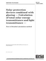
Key
CTS cover position
NOTE An explanation of the numbers used in this figure is given in Annex A.
Figure 101 - Types and application of CTS/CDS for wall or ceiling installation
BS EN 50085-2-1:2006+A1:2011
EN 50085-2-1:2006+A1:2011 (E)
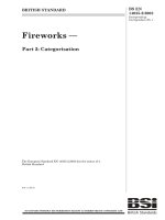
Figure 102a - Rectangular or similar
cross section CTS/CDS
– 16 –
Figure 102b – Non rectangular cross section CTS/CDS
Key
X
External horizontal dimension
F
Vertical deflection
Figure 102 - Arrangement for cable support test according to 10.2.2
Figure 103a - Rectangular or similar cross
section CTS/CDS
Figure 103b – Non rectangular cross
section CTS/CDS
Figure 103 - Arrangement for cable support test according to 10.2.3
– 17 –
Figure 104a - Rectangular or similar cross
section CTS/CDS
BS EN 50085-2-1:2006+A1:2011
EN 50085-2-1:2006+A1:2011 (E)
Figure 104b - Non rectangular cross section
CTS/CDS
Key
X
External horizontal dimension
F
Vertical deflection
Figure 104 - Arrangement for cable support test according to 10.2.4
Figure 105a - Rectangular or similar cross
section CTS/CDS
Figure 105b – Non rectangular cross section
CTS/CDS
Figure 105 - Arrangement for cable support test according to 10.2.5
BS EN 50085-2-1:2006+A1:2011
EN 50085-2-1:2006+A1:2011 (E)
– 18 –
L
W
W
L
L
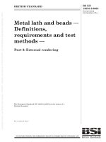
Figure 106a - Example with fitting
L
W
W
L
L
Figure 106b - Example without fitting
Key
Functional area associated with the function of the system (T derivation in this example)
W
Width of the trunking length
L
Maximum between W and 250 mm
Figure 106 - Impact test for installation and application – Principles for arrangement