Ipc 2541 eng american national standards institute (ansi)
Bạn đang xem bản rút gọn của tài liệu. Xem và tải ngay bản đầy đủ của tài liệu tại đây (985.94 KB, 175 trang )
ASSOCIATION CONNECTING
ELECTRONICS INDUSTRIES ®
IPC-2541
Generic Requirements for
Electronics Manufacturing
Shop-Floor Equipment
Communication Messages
(CAMX)
Endorsed by the National
Electronics Manufacturing
Initiative (NEMI)
IPC-2541
October 2001
A standard developed by IPC
3000 Lakeside Drive, Suite 309S, Bannockburn, IL 60015-1219
Tel. 847.615.7100 Fax 847.615.7105
www.ipc.org
The Principles of
Standardization
In May 1995 the IPC’s Technical Activities Executive Committee adopted Principles of
Standardization as a guiding principle of IPC’s standardization efforts.
Standards Should:
• Show relationship to Design for Manufacturability
(DFM) and Design for the Environment (DFE)
• Minimize time to market
• Contain simple (simplified) language
• Just include spec information
• Focus on end product performance
• Include a feedback system on use and
problems for future improvement
Notice
Standards Should Not:
• Inhibit innovation
• Increase time-to-market
• Keep people out
• Increase cycle time
• Tell you how to make something
• Contain anything that cannot
be defended with data
IPC Standards and Publications are designed to serve the public interest through eliminating
misunderstandings between manufacturers and purchasers, facilitating interchangeability and
improvement of products, and assisting the purchaser in selecting and obtaining with minimum
delay the proper product for his particular need. Existence of such Standards and Publications
shall not in any respect preclude any member or nonmember of IPC from manufacturing or selling products not conforming to such Standards and Publication, nor shall the existence of such
Standards and Publications preclude their voluntary use by those other than IPC members,
whether the standard is to be used either domestically or internationally.
Recommended Standards and Publications are adopted by IPC without regard to whether their
adoption may involve patents on articles, materials, or processes. By such action, IPC does
not assume any liability to any patent owner, nor do they assume any obligation whatever to
parties adopting the Recommended Standard or Publication. Users are also wholly responsible
for protecting themselves against all claims of liabilities for patent infringement.
IPC Position
Statement on
Specification
Revision Change
It is the position of IPC’s Technical Activities Executive Committee (TAEC) that the use and
implementation of IPC publications is voluntary and is part of a relationship entered into by
customer and supplier. When an IPC standard/guideline is updated and a new revision is published, it is the opinion of the TAEC that the use of the new revision as part of an existing
relationship is not automatic unless required by the contract. The TAEC recommends the use
of the lastest revision.
Adopted October 6. 1998
Why is there
a charge for
this standard?
Your purchase of this document contributes to the ongoing development of new and updated
industry standards. Standards allow manufacturers, customers, and suppliers to understand one
another better. Standards allow manufacturers greater efficiencies when they can set up their
processes to meet industry standards, allowing them to offer their customers lower costs.
IPC spends hundreds of thousands of dollars annually to support IPC’s volunteers in the
standards development process. There are many rounds of drafts sent out for review and
the committees spend hundreds of hours in review and development. IPC’s staff attends and
participates in committee activities, typesets and circulates document drafts, and follows all
necessary procedures to qualify for ANSI approval.
IPC’s membership dues have been kept low in order to allow as many companies as possible
to participate. Therefore, the standards revenue is necessary to complement dues revenue. The
price schedule offers a 50% discount to IPC members. If your company buys IPC standards,
why not take advantage of this and the many other benefits of IPC membership as well? For
more information on membership in IPC, please visit www.ipc.org or call 847/597-2872.
Thank you for your continued support.
©Copyright 2001. IPC, Bannockburn, Illinois. All rights reserved under both international and Pan-American copyright conventions. Any
copying, scanning or other reproduction of these materials without the prior written consent of the copyright holder is strictly prohibited and
constitutes infringement under the Copyright Law of the United States.
IPC-2541
ASSOCIATION CONNECTING
ELECTRONICS INDUSTRIES ®
CAMX
– GENERIC
Generic Requirements for
Electronics Manufacturing
Shop-Floor Equipment
Communication Messages
(CAMX)
A standard developed by the Generic Shop Floor XML Schema Formatting Task
Group (2-13a) of the Shop Floor Communications Subcommittee (2-13) of IPC.
The IPC-2541 standard defines an XML encoding schema, which enables a
detailed definition of electronics assembly, inspection, and test equipment
messages to be encoded at a level appropriate to facilitate plug-and-play
characteristics in a factory’s shop-floor information system.
This project was initiated by the NEMI Plug-and-Play Factory Project which
established proof of concept. After completion, the project leaders recommended
standardization by IPC under the ANSI rules and procedures.
November 20, 2001
Users of this standard are encouraged to participate in the
development of future revisions.
Contact:
IPC
3000 Lakeside Drive, Suite 309S
Bannockburn, Illinois
60015-1219
Tel 847 615.7100
Fax 847 615.7105
IPC-2541
October 2001
Acknowledgment
Any Standard involving a complex technology draws material from a vast number of sources. While the principal members
of the Generic Shop Floor XML Schema Formatting Task Group (2-13a) of the Shop Floor Communications Subcommittee (2-13) are shown below, it is not possible to include all of those who assisted in the evolution of this standard. To each
of them, the members of the IPC extend their gratitude.
Shop Floor Communications
Subcommittee
Generic Shop Floor XML Schema
Formatting Task Group
Technical Liaison of the
IPC Board of Directors
Chair
Allan Fraser
GenRad Inc.
Chair
Allan Fraser
GenRad Inc.
Stan Plzak
SMTC Manufacturing Corp.
Generic Shop Floor XML Schema Formatting Task Group
Tom Baggio, Panasonic Factory
Automation Company
Mike Hamblin, GenRad Inc.
Cord Burmeister, Siemens Dematic
AG
Dave Kerem, Camalot Division,
Speedline Technologies
Tom Dinnel, Universal Instruments
Miles Moreau, KIC
Mike Rogers, DEK Printing
Machines Ltd.
Andrew D. Dugenske, Georgia
Institute of Technology
Dave J. Morris, Nortel Networks
Hannu Ronkainen, JOT Automation
Hitoshi Nakamura, Matsushita
Electric Industrial Co. Ltd.
Bob Voitus, Celestica Inc.
Allan Fraser, GenRad Inc.
Frank Gearhart, Assembleon
Bob Neal, Agilent Technologies
Yoshiyuki Hattori, Matsushita
Electric Industrial Co. Ltd.
Andy Oughton, DEK Printing
Machines Ltd.
Nam Hoang, KIC
Jim Perilli, MPM Division, Speedline
Technologies
Jari Pirkola, JOT Automation
Mark Williams, Motorola
A special note of thanks goes to the following individuals for their dedication to bringing this project to fruition. We would
also like to highlight those individuals who were involved with the initial NEMI program concept and made major contributions to the development of the standard.
Allan Fraser, GenRad, Incorporated
Tom Dinnel, Universal Instruments
Mark Williams, Motorola
ii
Andy Dugenske, Georgia Institute of
Technology
David Kerem, Speedline
Technologies
Bob Voitus, Celestica, Inc.
Robert E. Neal, Agilent Technologies
Table of Contents
1
Scope ............................................................................................................................ 1
2
1.1
Interpretation....................................................................................................... 1
Applicable documents .................................................................................................... 1
3
General Requirements ................................................................................................... 2
4
3.1
Terms and Definitions.......................................................................................... 2
3.2
Date and Time Notation ....................................................................................... 3
3.3
CAMX Compliance .............................................................................................. 3
Equipment State Model .................................................................................................. 4
5
Multiple Zone and Multiple Lane Equipment State Prioritization ..................................... 10
6
Equipment Alarm, Error, Warning, and Information Messages ....................................... 10
7
Event Extensions ......................................................................................................... 11
7.1
7.2
7.3
7.4
7.5
7.6
Equipment Heart Beat Event .............................................................................. 11
7.1.1 Event: EquipmentHeartbeat ..................................................................... 11
Equipment State Change Event ......................................................................... 12
7.2.1 Event: EquipmentChangeState................................................................. 12
Item Events ....................................................................................................... 13
7.3.1 Event: ItemWorkStart............................................................................... 13
7.3.2 Event: ItemWorkPause ............................................................................ 13
7.3.3 Event: ItemWorkResume.......................................................................... 14
7.3.4 Event: ItemWorkAbort .............................................................................. 14
7.3.5 Event: ItemWorkComplete........................................................................ 15
7.3.6 Event: ItemTransferIn .............................................................................. 15
7.3.7 Event: ItemTransferOut............................................................................ 16
7.3.8 Event: ItemTransferZone ......................................................................... 16
7.3.9 Event: ItemTransferLane.......................................................................... 17
7.3.10 Event: ItemIdentifierRead ........................................................................ 17
7.3.11 Event: ItemInformation ............................................................................. 18
Lane Flow Events .............................................................................................. 19
7.4.1 Event: LaneStarved ................................................................................. 19
7.4.2 Event: LaneUnStarved ............................................................................. 19
7.4.3 Event: LaneBlocked ................................................................................. 20
7.4.4 Event: LaneUnBlocked............................................................................. 20
Equipment Flow Events ..................................................................................... 21
7.5.1 Event: EquipmentStarved......................................................................... 21
7.5.2 Event: EquipmentUnStarved .................................................................... 21
7.5.3 Event: EquipmentBlocked ........................................................................ 22
7.5.4 Event: EquipmentUnBlocked .................................................................... 22
Equipment Events ............................................................................................. 23
7.6.1 Event: EquipmentInitializationComplete.................................................... 23
7.6.2 Event: EquipmentSetupComplete ............................................................. 23
7.6.3 Event: EquipmentStartSelected ................................................................ 24
7.6.4 Event: EquipmentSetupSelected .............................................................. 24
iii
8
7.6.5 Event: EquipmentDownSelected .............................................................. 25
7.6.6 Event: EquipmentPowerOff ...................................................................... 25
7.6.7 Event: EquipmentRecipeSelected ............................................................ 26
7.6.8 Event: EquipmentRecipeReady ................................................................ 26
7.6.9 Event: EquipmentSelectedRecipeModified................................................ 27
7.6.10 Event: EquipmentNonSelectedRecipeModified ......................................... 27
7.6.11 Event: EquipmentParameterModified........................................................ 28
7.6.12 Event: EquipmentAlarm ........................................................................... 28
7.6.13 Event: EquipmentAlarmCleared................................................................ 29
7.6.14 Event: EquipmentAlarmsCleared .............................................................. 29
7.6.15 Event: EquipmentError............................................................................. 30
7.6.16 Event: EquipmentErrorCleared ................................................................. 30
7.6.17 Event: EquipmentErrorsCleared ............................................................... 31
7.6.18 Event: EquipmentWarning........................................................................ 31
7.6.19 Event: EquipmentWarningCleared ............................................................ 32
7.6.20 Event: EquipmentWarningsCleared .......................................................... 32
7.6.21 Event: EquipmentInformation ................................................................... 33
7.7
Operator Information Events .............................................................................. 34
7.7.1 Event: OperatorInformation ...................................................................... 34
7.7.2 Event: OperatorActionRegistered ............................................................. 34
7.7.3 Event: WaitingforOperatorAction .............................................................. 35
Equipment Flow Event Scenarios – Single Lane Equipment........................................... 36
9
8.1
Scenario 1 – Single Working Zone, Single Item .................................................. 36
8.2
Scenario 2 – Single Working Zone, Multiple Items .............................................. 44
8.3
Scenario 3 – Single Working Zone, Multiple Items, Downstream Bottleneck ........ 56
8.4
Scenario 4 – Single Working Zone, Equipment Error .......................................... 69
Equipment Flow Event Scenarios – Dual Lane Equipment ............................................. 80
9.1
Scenario 5 – Single Working Zone, Single Item .................................................. 80
9.2
Scenario 6 – Single Working Zone, Multiple Items .............................................. 93
10 2541 XML Schema ..................................................................................................... 121
10.1
10.2
10.3
10.4
10.5
10.6
10.7
10.8
10.9
10.10
10.11
10.12
10.13
10.14
EquipmentAlarm .............................................................................................. 122
EquipmentAlarmCleared .................................................................................. 123
EquipmentAlarmsCleared ................................................................................ 124
EquipmentBlocked........................................................................................... 125
EquipmentChangeState ................................................................................... 126
EquipmentDownSelected ................................................................................. 127
EquipmentError ............................................................................................... 128
EquipmentErrorCleared ................................................................................... 129
EquipmentErrorsCleared.................................................................................. 130
EquipmentHeartbeat ........................................................................................ 131
EquipmentInformation...................................................................................... 132
EquipmentInitializationComplete ...................................................................... 133
EquipmentNonSelectedRecipeModified ............................................................ 134
EquipmentParameterModified .......................................................................... 135
iv
10.15
10.16
10.17
10.18
10.19
10.20
10.21
10.22
10.23
10.24
10.25
10.26
10.27
10.28
10.29
10.30
10.31
10.32
10.33
10.34
10.35
10.36
10.37
10.38
10.39
10.40
10.41
10.42
10.43
10.44
10.45
EquipmentPowerOff......................................................................................... 136
EquipmentRecipeReady .................................................................................. 137
EquipmentRecipeSelected ............................................................................... 138
EquipmentSelectedRecipeModified .................................................................. 139
EquipmentSetupComplete ............................................................................... 140
EquipmentSetupSelected................................................................................. 141
EquipmentStartSelected .................................................................................. 142
EquipmentStarved ........................................................................................... 143
EquipmentUnBlocked ...................................................................................... 144
EquipmentUnStarved ....................................................................................... 145
EquipmentWarning .......................................................................................... 146
EquipmentWarningCleared .............................................................................. 147
EquipmentWarningsCleared............................................................................. 148
ItemIdentifierRead ........................................................................................... 149
ItemInformation ............................................................................................... 150
ItemTransferIn................................................................................................. 151
ItemTransferLane ............................................................................................ 152
ItemTransferOut .............................................................................................. 153
ItemTransferZone ............................................................................................ 154
ItemWorkAbort ................................................................................................ 155
ItemWorkComplete .......................................................................................... 156
ItemWorkPause ............................................................................................... 157
ItemWorkResume ............................................................................................ 158
ItemWorkStart ................................................................................................. 159
LaneBlocked ................................................................................................... 160
LaneStarved.................................................................................................... 161
LaneUnBlocked ............................................................................................... 162
LaneUnStarved ............................................................................................... 163
OperatorActionRegistered................................................................................ 164
OperatorInformation ........................................................................................ 165
WaitingForOperatorAction................................................................................ 166
v
IPC-2541
October 2001
Generic Requirements for Electronics Manufacturing
Shop-Floor Equipment Communication Messages (CAMX)
Introduction
Factory Information Systems (FIS) form the nervous system of an enterprise, analysing data and
delivering information to the machines and people who need to make information-based
decisions. These systems provide a bi-directional flow of information between the factory floor
and the rest of the enterprise. The National Electronics Manufacturing Initiative’s (NEMI) Plug &
Play Factory project addressed some critical problems involving factory information system
deployment on the electronics manufacturing factory floor. The Plug & Play Factory project
focused on the development of the standards necessary to achieve interoperability, or plug-andplay capability, on the factory floor. Activities were comprised of three areas:
•
Definition of standards for a software framework that will allow interoperability between
equipment produced by different vendors.
•
Development of process-specific, machine communication interface standards for surface
mount equipment. These standards will leverage the Generic Equipment Model (GEM)
specification developed for semiconductor equipment and web-based standards for data
transmission.
•
Establishment of a test-bed manufacturing line to prove out the concepts developed by the
project.
1
Scope
The IPC-2541 standard defines an XML encoding schema to facilitate plug-and-play
characteristics in a factory’s shop-floor information system. This standard describes the generic
event message content, and should be used together with the IPC-2540 series sectional
documents, which define the set of messages and key attributes of specific classes of equipment
used in the electronics manufacturing area.
1.1 Interpretation
"Shall", the emphatic form of the verb, is used throughout this standard whenever a requirement
is intended to express a provision that is mandatory. Deviation from a shall requirement is not
permitted, and compliance with the XML syntax and semantics shall be followed without
ambiguity, or the insertion of superfluous information.
The words "should" and "may" are used whenever it is necessary to express non-mandatory
provisions.
"Will" is used to express a declaration of purpose.
To assist the reader, the word shall is presented in bold characters.
2
Applicable documents
The following documents contain provisions that, through reference in this text, constitute
provisions of this standard. All documents are subject to revision. Parties who make agreements
1
IPC-2541
October 2001
based on this standard are encouraged to investigate the possibility of applying the most recent
editions of the documents indicated below.
IPC-T-50
Terms and Definitions for Interconnecting and Packaging Electronic Circuits
IPC-2501 Generic Computer Aided Manufacturing (CAMX) Framework definitions
IPC-2511 Generic Computer Aided Manufacturing (GenCAM) descriptions for Printed Circuit
Boards and Printed Board Assembly
IPC-2546 Sectional Requirements for Shop-Floor Equipment Communication Messages (CAMX)
for Printed Circuit Board Assembly
IPC-2547 Sectional Requirements for Shop-Floor Equipment Communication Messages (CAMX)
for Printed Circuit Board Test, Inspection and Rework
3
General Requirements
The requirements of IPC-2501 are a mandatory part of this standard. That document describes
the generic requirements for the CAMX format.
3.1 Terms and Definitions
Downstream equipment
A piece of equipment located after another piece of equipment in a line.
Equipment Controller Down
The equipment cannot process instructions without operator or other personnel intervention.
Equipment Controller Up
When the equipment controller is running and the equipment Web client can send messages.
Equipment State
The various possible conditions of a piece of equipment. These include states such as ready,
setup, down, and off.
Initialization
A normal directed process for the equipment to reach the state for its intended production
function such as homing, calibration or initialization.
Item
An individual unit that is processed. An item usually consists of a single printed circuit board or a
panelized board containing multiple circuits.
Item instance identifier
Item instance identifier is an identifier for an item. An item instance identifier may be derived
from the serial number. If a bar code reader is present then the item instance identifier may be
the bar code label that is read. If no bar code reader is present then the item instance identifier
may be generated by the piece of equipment.
Lane
A lane is an independent processing path through a piece of equipment. A single piece of
equipment may have multiple lanes.
2
IPC-2541
October 2001
Upstream equipment
A piece of equipment located before another piece of equipment in a line.
Zone
A staging area or a working area within a piece of equipment. A single piece of equipment may
have many zones.
3.2 Date and Time Notation
All 2540 standards shall use the World Wide Web consortium (W3C) date time standard. This
standard shall use the Complete Date plus Hours, Minutes, Seconds, and a decimal fraction of a
second and Time Zone Designator. Two decimal places will be used in order to represent time
down to a hundredth of a second. For additional information on date and time, see web page:
/>3.3 CAMX Compliance
All events defined in 2541 that are applicable to a piece of equipment shall be implemented in
order to comply with this standard. The only exception to this rule is that for a single lane piece
of equipment it is not required for the equipment to send the LaneStarved, LaneUnStarved,
LaneBlocked, and LaneUnBlocked events. In addition, 2541 events can be extended in the 2540
series sectional documents. All of the attribute names defined in 2541 events must also be
present in the events that are extended in the sectionals. All attribute names that are used to
extend events defined in the sectionals must have different names than the attribute names
defined in 2541. Individual equipment suppliers can also extend any events defined in the 2540
series of standards, providing they support all attribute names defined in the 2540 series of
documents.
Equipment performance data will be included in specific event definitions that are defined or
extended in each of the sectionals. The CAMX reporting mechanism will be different from how
GEM reporting works today. Key reporting data will be defined in the 2540 sectionals that detail
the information to be sent from the equipment when certain events occur on the equipment. For
example, in the 2546 sectional, a placement machine pick error may be accompanied by the
nozzle that performed the mis-pick, along with counts of previously successful picks by that
nozzle, each time a component mis-pick event occurs on the equipment.
The IPC-2541 document defines a set of Equipment, Recipe, Item, and Operator events and
related message formats. The IPC-2501 document defines a message packet structure. All shop
floor equipment that complies with the IPC-2541 standards shall also comply with the event
messages contained in the IPC-2501 standard as well as those events that are described in this
document. All event messages shall be formatted in compliance with the IPC-2501. The
following is a typical message example. The latest IPC-2501 requirements are available at
/><?xml version="1.0" " encoding = "UTF-8"?>
<!--Sample IPC2501/IPC2541 Message -->
<Envelope xmlns:xsi = " />xsi:noNamespaceSchemaLocation = " />xmlns:IPC2541 = " />sender = "myhost.xyz.com/Line3/Machine1"
messageID = "15.11.9.54.+2001-01-23T19:20:30.27+05:00"
dateTime = "2001-01-23T19:20:30.27+05:00"
messageSchema = " />
3
IPC-2541
October 2001
descriptionLanguage = "en"
action = "PUBLISH">
<Message>
softwareRev = "Rev 3.2.0"
hardwareRev = "Rev 7-B"/>
</Message>
</Envelope>
4
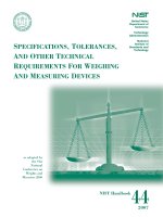
Equipment State Model
The objective of the equipment state model is to capture important machine status information
that can be used to track machine utilization and availability. It is useful in the monitoring and
control of resources in automated surface mount (SMT) lines. A processing station in the SMT
line processes raw materials to produce finished or semi-finished products, as shown below in
Figure 1.
Host
Client
Machine operator
Set-up materials
Items (PCB's)
SMT equipment
Figure 1 Elements Related to Equipment Monitoring and Control
The goals of the development of the CAMX equipment state model are the following:
1. Create an equipment state model and define states applicable to the electronics assembly,
inspection, and test industry. This endeavor is analogous to that which resulted in the
Semiconductor Equipment and Materials International (SEMI) E-10 standard for the
semiconductor industry.
2. Minimize the number of states. Each state must have significance for process monitoring and
control.
3. Define states so that no variations in the basic states are allowed in implementations.
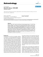
The equipment model consists of three components: The state diagram, the state transition table
and the events that trigger these state transitions. The state transitions are triggered by material
4
IPC-2541
October 2001
conditions, alarms, or operator or host inputs. In all cases the equipment shall send the
appropriate message when the corresponding physical event occurs on the equipment.
The CAMX equipment state diagram is shown in Figure 2.
Off
0
Setup
1
2
Ready
7
8
Idle
Blocked
3
Starved
4
5
6
Down
Processing
Active
Executing
9
Figure 2 CAMX Equipment State Diagram
Some typical equipment state transitions are shown in Table 2. A complete listing of all of the
event state transitions is shown in Table 3.
5
IPC-2541
October 2001
Table 2 Example State Transition Table for Equipment State Model
Arrow
Current state
Typical trigger
Specific example
New state
0
OFF
Power On (Default
entry)
EquipmentInitializationComplete
SETUP
1
SETUP
Complete Setup
EquipmentSetupComplete
Any READY substate or DOWN
2
READY
Start Setup
EquipmentSetupSelected
SETUP
3
READYIDLESTARVED
Material Received
EquipmentUnStarved
READYPROCESSINGACTIVE
4
READYPROCESSINGACTIVE
Material Output
Blocked
EquipmentBlocked
READYIDLEBLOCKED
5
DOWN
Press "Start"
EquipmentStartSelected
Any READY substate
6
READY
Out of Supply
EquipmentAlarm
DOWN
7
SETUP
Major Error
EquipmentError
DOWN
8
DOWN
Start Setup
EquipmentSetupSelected
SETUP
9
DOWN
Controlled
Shutdown
EquipmentPowerOff
OFF
Each piece of equipment must track its own state. Each state is mutually exclusive. Each event
can cause the equipment to enter one and only one new state. At any point in time, the state of a
piece of equipment is uniquely determined by the most recent event that occurred on the
equipment.
The terms used to refer to the various equipment states are defined as follows:
IDLE means a piece of equipment is ready to process items but is not doing so. The piece of
equipment may be in either the STARVED or BLOCKED sub-states.
STARVED is a sub-state of IDLE. This is the state of a piece of equipment when it is ready to
receive an item from an upstream piece of equipment but no item is available. The equipment’s
working area is available to work but it is not being given anything to build. There is no
unfinished work within the equipment and there are no items available to move into the
equipment. The equipment is empty and it can’t pull any items in to work on.
BLOCKED is a sub-state of IDLE. This is the state of a piece of equipment when it is ready to
send completed items to a downstream piece of equipment but it is prevented from doing so by
the downstream piece of equipment. Processing of all items in a working zone within the
equipment has been completed. The equipment is unable to accept any new items into its
staging or working zones. The equipment is full and it can’t push any items out.
PROCESSING means that a piece of equipment is productively working on an item. The piece of
equipment may be in either the ACTIVE or EXECUTING sub-states.
6
IPC-2541
October 2001
EXECUTING is the sub-state of PROCESSING in which the equipment is executing a recipe and
it can continue to do so without external intervention. The executing sub-state includes times like
fiducial finding and board alignment for a piece of placement equipment.
ACTIVE is the sub-state of PROCESSING when an item is available but no recipe is being
executed. This includes time intervals when items are transferring into a piece of equipment, out
of a piece of equipment, or between different zones within a piece of equipment.
READY is a superset of the PROCESSING and IDLE states.
SETUP means that a piece of equipment is being configured. Set-up involves a deliberate action
being taken on the equipment.
DOWN means that a piece of equipment can not produce items either due to a lack of
components or other consumable material, an equipment malfunction, host or operator
intervention,or equipment initiated events. A piece of equipment that is in the DOWN state is not
in the SETUP, READY, or OFF states.
OFF means that a piece of equipment has been powered down and is not available for
production.
Table 3 Complete State Transition Table for Equipment State Model
EVENT NAME
SEE
PARA
TYPICAL TRIGGER
CURRENT
STATE
NEXT STATE
EquipmentAlarm
7.6.12
Unsafe condition for operator or
machine has occurred.
Any
DOWN
EquipmentAlarmCleared
7.6.13
Alarm condition has been
removed.
DOWN
DOWN
EquipmentAlarmsCleared
7.6.14
All alarm conditions have been
removed.
DOWN
DOWN
EquipmentBlocked
7.5.3
Item work is complete but output
queue is not available.
READYPROCESSINGACTIVE
READYIDLEBLOCKED
EquipmentChangeState
7.2.1
An event caused an equipment
State Change
Any
Any Other
EquipmentDownSelected
7.6.5
The operator or host has selected
the equipment down mode.
Any Other
DOWN
EquipmentError
7.6.15
Trapped equipment error.
Any
DOWN
EquipmentErrorCleared
7.6.16
Operator or other interaction has
removed the error condition.
DOWN
DOWN
EquipmentErrorsCleared
7.6.17
All error conditions have been
removed.
DOWN
DOWN
7.1.1
Equipment sends a keep alive
message.
Any
Same
Informational message emitted.
Any
Same
EquipmentHeartbeat
EquipmentInformation
7.6.21
EquipmentInitializationComplete
7.6.1
Boot process has completed and
the equipment is ready for recipe
and material.
OFF
SETUP
EquipmentNonSelectedRecipeModified
7.6.10
A non-selected recipe has been
modified by the operator or host
computer
Any
Same
7
IPC-2541
October 2001
EVENT NAME
EquipmentParameterModified
SEE
PARA
TYPICAL TRIGGER
CURRENT
STATE
NEXT STATE
7.6.11
Equipment parameter has been
changed, either by the operator or
by the host.
Any
Same
EquipmentPowerOff
7.6.6
Equipment is being powered down
via a controlled shutdown
procedure.
DOWN
OFF
EquipmentRecipeReady
7.6.8
The recipe file is loaded.
Any
Same
EquipmentRecipeSelected
7.6.7
Recipe file has been selected
Any
Same
EquipmentSelectedRecipeModified
7.6.9
Selected recipe has been modified
by the operator or host computer.
Any
Same
EquipmentSetupComplete
7.6.2
Equipment has completed setup.
SETUP
Any READY
sub-state or
DOWN
EquipmentSetupSelected
7.6.4
The operator or host has selected
the equipment setup mode.
Any Other
SETUP
EquipmentStartSelected
7.6.3
The equipment itself, an operator,
or host has selected the equipment
start mode.
Any Other
Any READY
sub-state
EquipmentStarved
7.5.1
Equipment is ready but there is no
product item available.
Any Other
READYIDLESTARVED
EquipmentUnBlocked
7.5.4
Equipment has been blocked and
output queue becomes available.
READYIDLEBLOCKED
READYPROCESSINGACTIVE
EquipmentUnStarved
7.5.2
Equipment has been starved and
now there is new product available.
READYIDLESTARVED
READYPROCESSINGACTIVE
EquipmentWarning
7.6.18
Warning message emitted
Any
Same
EquipmentWarningCleared
7.6.19
Warning condition cleared
Any
Same
EquipmentWarningsCleared
7.6.20
All warning conditions cleared
Any
Same
ItemIdentifierRead
7.3.10
An item is available and its
Identification label has been read
successfully.
READYPROCESSINGACTIVE
Same
ItemInformation
7.3.11
Non-threatening item information is
emitted.
Any
Same
ItemTransferIn
7.3.6
An item has entered the
equipment.
Any
Same
ItemTransferLane
7.3.9
An item has transferred from one
equipment lane to another.
Any
Same
ItemTransferOut
7.3.7
An item has transferred out of the
equipment.
Any
Same
ItemTransferZone
7.3.8
An item has transferred from one
equipment zone to another.
Any
Same
ItemWorkAbort
7.3.4
Process work that has been
paused on an item is aborted.
READYPROCESSINGACTIVE
Same
ItemWorkComplete
7.3.5
Process work on an item is
complete.
READYPROCESSINGEXECUTING
READYPROCESSINGACTIVE
8
IPC-2541
October 2001
EVENT NAME
SEE
PARA
TYPICAL TRIGGER
CURRENT
STATE
NEXT STATE
ItemWorkPause
7.3.2
Process execution on an item has
been paused.
READYPROCESSINGEXECUTING
READYPROCESSINGACTIVE
ItemWorkResume
7.3.3
Process work on an item has been
restarted.
READYPROCESSINGACTIVE
READYPROCESSINGEXECUTING
ItemWorkStart
7.3.1
The equipment begins executing
its process on a product item.
Any READY
Sub-state
READYPROCESSINGEXECUTING
LaneBlocked
7.4.3
Item work is complete but output
queue is not available for that lane.
Any
Same
LaneStarved
7.4.1
Equipment lane is ready but there
is no item to process.
Any
Same
LaneUnBlocked
7.4.4
Equipment lane has been blocked
and output queue becomes
available
Any
Same
LaneUnStarved
7.4.2
Equipment lane has been starved
and now there is a new item
available to process.
Any
Same
OperatorActionRegistered
7.7.2
An operator intervention has taken
place.
Any
Same
OperatorInformation
7.7.1
Operator instigated information
message is emitted.
Any
Same
WaitingForOperatorAction
7.7.3
The process is halted for a reason
other than a starved or blocked
piece of equipment and human
intervention is required before
processing can resume.
Any
Down
9
IPC-2541
5
In
or
of
of
October 2001
Multiple Zone and Multiple Lane Equipment State Prioritization
order to give further clarification to the state of a piece of equipment containing multiple lanes
zones the following rule will be used. When any of the lanes of a piece of equipment, or any
the zones within a lane, is in one of the following states, the equipment will assume the state
the lane or the zone that has the highest priority according to the priorities shown in Table 4.
Table 4 – Prioritization of Multiple Lane/Multiple
Working Zone Equipment States
PRIORITY (1= Highest)
6
STATE
1
READY-PROCESSING-EXECUTING
2
READY-PROCESSING-ACTIVE
3
READY-IDLE-STARVED
4
READY-IDLE-BLOCKED
5
SETUP
6
DOWN
7
OFF
Equipment Alarm, Error, Warning, and Information Messages
Equipment alarms are events which are sent when dangerous conditions occur that can cause
danger to either people or equipment if not addressed immediately.
Equipment errors are events which cause the equipment to malfunction and not operate
correctly.
Equipment warnings are events which do not cause any immediate problems. Equipment
warnings may escalate into either equipment error conditions or equipment alarm conditions if
not addressed.
Equipment information messages are generated by the equipment when an interesting event
occurs on the equipment.
The difference between equipment warnings and equipment error messages is that warnings do
not change the state of the machine, whereas equipment errors do change the state of the
machine.
The difference between equipment warnings and equipment information messages is that
equipment warnings do need to be cleared whereas equipment information messages do not
need to be cleared.
Table 5 illustrates the differences between Equipment Alarm, Error, Warning, and Information
messages.
EquipmentAlarm, EquipmentError, and EquipmentWarning events must maintained when the
equipment is powered down and back up again.
10
IPC-2541
October 2001
If a piece of equipment determines that it cannot communicate then it must be able to spool all
events locally.
Table 5 – Equipment Alarms, Errors, Warning,
and Information Events Characteristics
7
Tracked by
Equipment
Cleared by
Equipment or Host
State Change
Dangerous
Condition
Alarms
Y
Y
Y
Y
Errors
Y
Y
Y
N
Warnings
Y
Y
N
N
Information
N
N
N
N
Event Extensions
All 2541, 2546, and 2547 messages can be extended. An element called Extensions will be
included in each event. See the 2541 XML Schema section for a complete listing of the XML
schema used in the 2541 standard. The following sections show the name for each event, along
with any state changes associated with the event, the description of the event, all attributes and
their type for each event, as well as an illustrative example of how that event could be used in
an actual production situation. The right-most column indicates the expected number of
occurrences (cardinality) of each attribute or element. In this standard all attributes or elements
are mandatory as is indicated by 1-1. The IPC-2546 and IPC-2547 use 0-1 to indicate an
optional field. 1-1 to indicate a single mandatory field. 0-n to indicate any number, including
zero. 1-n indicates at least one.
7.1 Equipment Heart Beat Event
7.1.1 Event: EquipmentHeartbeat
StateChange: This event does not cause any state changes.
Description: This event sends a heart beat at a regular time interval from a piece of equipment.
Attribute Name
Attribute
Type
Description
Occ
dateTime
dateTime
Current date and time
1-1
Interval
Non-negative
integer
Time interval between heart beat events being sent by
the piece of equipment. A value of 0 means that the
equipment will send no further heart beat events.
1-n
interval=60
/>
11
IPC-2541
October 2001
7.2 Equipment State Change Event
7.2.1 Event: EquipmentChangeState
StateChange: This event reports a state change, it does not cause any state changes.
Description: This event occurs only when a piece of equipment changes state. This event
uniquely identifies the event that caused the equipment to change state. Even though there may
be many events occurring at the same time on a piece of equipment, the event identifier listed
here is the name of the event that caused the equipment to change state.
Attribute Name
Attribute
Type
Description
Occ
dateTime
dateTime
Current date and time
1-1
currentState
string
(enumerated)
READY-IDLE-BLOCKED |
READY-IDLE-STARVED |
READY-PROCESSING-ACTIVE |
READY-PROCESSING-EXECUTING |
SETUP | OFF
DOWN
1-1
previousState
string
(enumerated)
READY-IDLE-BLOCKED |
READY-IDLE-STARVED |
READY-PROCESSING-ACTIVE |
READY-PROCESSING-EXECUTING |
SETUP | OFF
DOWN
1-1
eventId
string
Event identifier which caused the state change
1-1
currentState="READY-PROCESSING-ACTIVE"
previousState="READY-IDLE-STARVED"
eventId="EquipmentUnStarved"
/>
12
IPC-2541
October 2001
7.3 Item Events
7.3.1 Event: ItemWorkStart
StateChange: Any READY Sub-state
Description: This event occurs when an item is starting to be worked on by a piece of
equipment. This event must be the first processing event for a specific item. This event must be
sent for every individual working zone. The ItemWorkComplete, ItemWorkAbort, or
ItemWorkPause events may follow this event.
Attribute Name
Attribute
Type
Description
Occ.
dateTime
dateTime
Current date and time
1-1
itemInstanceId
string
Item instance identifier
1-1
laneId
string
Line lane number
1-n
zoneId
string
Area segment number
1-n
itemInstanceId="001"
laneId="1"
zoneId="2"
/>
7.3.2 Event: ItemWorkPause
StateChange: Ready-Processing-Executing->Ready-Processing-Active
Description: This event occurs when an item is paused. A pause may be caused either by the
equipment itself, by an operator, or by a host computer. Either an ItemWorkResume event or an
ItemWorkAbort event must follow this event.
Attribute Name
Attribute
Type
Description
Occ.
dateTime
dateTime
Current date and time
1-1
itemInstanceId
string
Item instance identifier
1-1
laneId
string
Line lane identifier
1-n
zoneId
string
Area segment identifier
1-n
pauseId
string
Pause identifier
1-1
itemInstanceId="001"
laneId="1"
zoneId="2"
pauseId="Paused waiting for parts"
/>
13
IPC-2541
October 2001
7.3.3 Event: ItemWorkResume
StateChange: Ready-Processing-Active->Ready-Processing-Executing
Description: This event occurs when work on an item is resumed. This event may be triggered
either by an operator or by a host computer.
Attribute Name
Attribute Type
Description
Occ
dateTime
dateTime
Current date and time
1-1
itemInstanceId
string
Item instance identifier
1-1
laneId
string
Line lane identifier
1-n
zoneId
string
Area segment identifier
1-n
itemInstanceId="001"
laneId="Left"
zoneId="Curing"
/>
7.3.4 Event: ItemWorkAbort
StateChange: No state change.
Description: This event occurs when work on an item is aborted.
Attribute Name
Attribute Type
Description
Occ
dateTime
dateTime
Current date and time
1-1
itemInstanceId
string
Item instance identifier
1-1
laneId
string
Line lane identifier
1-n
zoneId
string
Area segment identifier
1-n
abortId
string
Abort identifier
1-1
itemInstanceId="001"
laneId="1"
zoneId="2"
abortId="Aborted due to bad material"
/>
14
IPC-2541
October 2001
7.3.5 Event: ItemWorkComplete
StateChange: Ready-Processing-Executing->Ready-Processing-Active
Description: This event indicates the completion of the processing of an item. This event must
be sent for every individual working zone. This event does not indicate anything about the quality
of the processing, it is merely indicating that the processing of that item is complete. This event
must be preceded by an ItemWorkStart message.
Attribute Name
Attribute Type
Description
Occ
dateTime
dateTime
Current date and time
1-1
itemInstanceId
string
Item instance identifier
1-1
laneId
string
Line lane identifier
1-n
zoneId
string
Area segment identifier
1-n
itemInstanceId="001"
laneId="1"
zoneId="2"
/>
7.3.6 Event: ItemTransferIn
StateChange: No State Change
Description: The item has finished transferring into the first zone of a piece of equipment.
Attribute Name
Attribute Type
Description
Occ
dateTime
dateTime
Current date and time
1-1
itemInstanceId
string
Item instance identifier
1-1
laneId
string
Line lane identifier
1-n
itemInstanceId="001"
laneId="1"
/>
15
IPC-2541
October 2001
7.3.7 Event: ItemTransferOut
StateChange: No State Change
Description: The item has finished transferring out of the last zone of a piece of equipment.
Attribute Name
Attribute Type
Description
Occ
dateTime
dateTime
Current date and time
1-1
itemInstanceId
string
Item instance identifier
1-1
laneId
string
Line lane identifier
1-n
itemInstanceId="001"
laneId="1"
/>
7.3.8 Event: ItemTransferZone
StateChange: No State Change
Description: The equipment sends this event when an item has finished transferring between
any two zones within a piece of equipment. This event must not be sent when an item enters the
first zone of a piece of equipment nor when it leaves the last zone of a piece of equipment. See
the ItemTransferIn and ItemTransferOut events for these two cases. The first zone inside a
machine must have a Zone identifier of 1.
Attribute Name
Attribute Type
Description
Occ
dateTime
dateTime
Current date and time
1-1
itemInstanceId
string
Item instance identifier
1-1
fromZoneId
string
From area segment identifier
1-n
toZoneId
string
To area segment identifier
1-n
laneId
string
Line lane identifier
1-n
itemInstanceId="001"
fromZoneId="2"
toZoneId="3"
laneId="1"
/>
16
IPC-2541
October 2001
7.3.9 Event: ItemTransferLane
StateChange: No State Change
Description: The equipment sends this event when an item has finished transferring between
any two lanes within a piece of equipment.
Attribute Name
Attribute Type
Description
Occ
dateTime
dateTime
Current date and time
1-1
itemInstanceId
string
Item instance identifier
1-1
fromLaneId
string
From lane segment identifier
1-n
toLaneId
string
To lane segment identifier
1-n
zoneId
string
Equipment zone identifier
1-n
itemInstanceId="001"
fromLaneId="2"
toLaneId="3"
zoneId="1"
/>
7.3.10 Event: ItemIdentifierRead
StateChange: No State Change
Description: This event is sent when an item’s label containing an identifier has been read by a
piece of equipment (e.g., barcode label, RF tag). If the equipment has label readers on the top
and bottom side of one lane, the scannerId must contain the location of the label readers.
Attribute Name
Attribute Type
Description
Occ
dateTime
dateTime
Current date and time
1-1
itemInstanceId
string
Item instance identifier
1-1
laneId
string
Line lane identifier
1-n
zoneId
string
Zone identifier
1-n
scannerId
string
Unique scanner identifier
1-1
itemInstanceId="001"
laneId="2"
zoneId="2"
scannerId="Input Conveyor, Placer 1-IC"
/>
17
IPC-2541
October 2001
7.3.11 Event: ItemInformation
StateChange: No State Change
Description: Item information messages that are directly related to the assembly process, and
are not associated with a specific machine subsystem. These indicate a no problem condition
without a recovery screen.
Attribute Name
Attribute Type
Description
Occ
dateTime
dateTime
Current date and time
1-1
itemInstanceId
string
Serial number, Product type, Lot Id
1-1
informationId
string
Information identifier
1-1
itemInstanceId="001"
informationId="EquipmentMessage56"
/>
18