Ipc 2546 eng american national standards institute (ansi)
Bạn đang xem bản rút gọn của tài liệu. Xem và tải ngay bản đầy đủ của tài liệu tại đây (3.31 MB, 114 trang )
ASSOCIATION CONNECTING
ELECTRONICS INDUSTRIES ®
IPC-2546
with Amendment 1
Sectional Requirements
for Shop-Floor Equipment
Communication Messages
(CAMX) for Printed Circuit
Board Assembly
Endorsed by the National
Electronics Manufacturing
Initiative (NEMI)
IPC-2546
with Amendment 1
January 2003
Supersedes IPC-2546
October 2001
A standard developed by IPC
3000 Lakeside Drive, Suite 309S, Bannockburn, IL 60015-1219
Tel. 847.615.7100 Fax 847.615.7105
www.ipc.org
The Principles of
Standardization
In May 1995 the IPC’s Technical Activities Executive Committee adopted Principles of
Standardization as a guiding principle of IPC’s standardization efforts.
Standards Should:
• Show relationship to Design for Manufacturability
(DFM) and Design for the Environment (DFE)
• Minimize time to market
• Contain simple (simplified) language
• Just include spec information
• Focus on end product performance
• Include a feedback system on use and
problems for future improvement
Notice
Standards Should Not:
• Inhibit innovation
• Increase time-to-market
• Keep people out
• Increase cycle time
• Tell you how to make something
• Contain anything that cannot
be defended with data
IPC Standards and Publications are designed to serve the public interest through eliminating
misunderstandings between manufacturers and purchasers, facilitating interchangeability and
improvement of products, and assisting the purchaser in selecting and obtaining with minimum
delay the proper product for his particular need. Existence of such Standards and Publications
shall not in any respect preclude any member or nonmember of IPC from manufacturing or selling products not conforming to such Standards and Publication, nor shall the existence of such
Standards and Publications preclude their voluntary use by those other than IPC members,
whether the standard is to be used either domestically or internationally.
Recommended Standards and Publications are adopted by IPC without regard to whether their
adoption may involve patents on articles, materials, or processes. By such action, IPC does
not assume any liability to any patent owner, nor do they assume any obligation whatever to
parties adopting the Recommended Standard or Publication. Users are also wholly responsible
for protecting themselves against all claims of liabilities for patent infringement.
IPC Position
Statement on
Specification
Revision Change
It is the position of IPC’s Technical Activities Executive Committee (TAEC) that the use and
implementation of IPC publications is voluntary and is part of a relationship entered into by
customer and supplier. When an IPC standard/guideline is updated and a new revision is published, it is the opinion of the TAEC that the use of the new revision as part of an existing
relationship is not automatic unless required by the contract. The TAEC recommends the use
of the lastest revision.
Adopted October 6. 1998
Why is there
a charge for
this standard?
Your purchase of this document contributes to the ongoing development of new and updated
industry standards. Standards allow manufacturers, customers, and suppliers to understand one
another better. Standards allow manufacturers greater efficiencies when they can set up their
processes to meet industry standards, allowing them to offer their customers lower costs.
IPC spends hundreds of thousands of dollars annually to support IPC’s volunteers in the
standards development process. There are many rounds of drafts sent out for review and
the committees spend hundreds of hours in review and development. IPC’s staff attends and
participates in committee activities, typesets and circulates document drafts, and follows all
necessary procedures to qualify for ANSI approval.
IPC’s membership dues have been kept low in order to allow as many companies as possible
to participate. Therefore, the standards revenue is necessary to complement dues revenue. The
price schedule offers a 50% discount to IPC members. If your company buys IPC standards,
why not take advantage of this and the many other benefits of IPC membership as well? For
more information on membership in IPC, please visit www.ipc.org or call 847/597-2872.
Thank you for your continued support.
©Copyright 2003. IPC, Bannockburn, Illinois. All rights reserved under both international and Pan-American copyright conventions. Any
copying, scanning or other reproduction of these materials without the prior written consent of the copyright holder is strictly prohibited and
constitutes infringement under the Copyright Law of the United States.
IPC-2546
ASSOCIATION CONNECTING
ELECTRONICS INDUSTRIES ®
CAMX
– ASSEMBLY
Sectional Requirements
for Shop-Floor Equipment
Communication Messages
(CAMX) for Printed Circuit
Board Assembly
A standard developed by the Assembly XML Schema Formatting Task Group
(2-13b) of the Shop Floor Communications Subcommittee (2-13) of IPC.
The IPC-2546 standard defines an XML encoding schema, specific to printed
ciruit board assembly equipment, which enables a detailed definition of electronics assembly equipment messages to be encoded at a level appropriate to
facilitate plug-and-play characteristics in a factory’s shop-floor information system.
This project was initiated by the NEMI Plug-and-Play Factory Project which
established proof of concept. After completion, the project leaders recommended
standardization by IPC under the ANSI rules and procedures.
March 10, 2003
Supersedes:
IPC-2546 - October 2001
Users of this standard are encouraged to participate in the
development of future revisions.
Contact:
IPC
3000 Lakeside Drive, Suite 309S
Bannockburn, Illinois
60015-1219
Tel 847 615.7100
Fax 847 615.7105
IPC-2546 with Amendment 1
January 2003
Acknowledgment
Any Standard involving a complex technology draws material from a vast number of sources. While the principal members
of the Assembly XML Schema Formatting Task Group (2-13b) of the Shop Floor Communications Subcommittee (2-13) are
shown below, it is not possible to include all of those who assisted in the evolution of this standard. To each of them, the
members of the IPC extend their gratitude.
Shop Floor Communications
Subcommittee
Assembly XML Schema
Formatting Task Group
Technical Liaison of the
IPC Board of Directors
Chair
Allan Fraser
GenRad Inc.
Chair
Tom Dinnel
Universal Instruments
Stan Plzak
SMTC Manufacturing Corp.
Assembly XML Schema Formatting Task Group
Tom Baggio, Panasonic Factory
Automation Company
Mike Hamblin, GenRad Inc.
Cord Burmeister, Siemens Dematic
AG
Dave Kerem, Camalot Division,
Speedline Technologies
Tom Dinnel, Universal Instruments
Miles Moreau, KIC
Mike Rogers, DEK Printing
Machines Ltd.
Andrew D. Dugenske, Georgia
Institute of Technology
Dave J. Morris, Nortel Networks
Hannu Ronkainen, JOT Automation
Hitoshi Nakamura, Matsushita
Electric Industrial Co. Ltd.
Bob Voitus, Celestica Inc.
Allan Fraser, GenRad Inc.
Frank Gearhart, Assembleon
Bob Neal, Agilent Technologies
Yoshiyuki Hattori, Matsushita
Electric Industrial Co. Ltd.
Andy Oughton, DEK Printing
Machines Ltd.
Nam Hoang, KIC
Jim Perilli, MPM Division, Speedline
Technologies
Jari Pirkola, JOT Automation
Mark Williams, Motorola
A special note of thanks goes to the following individuals for their dedication to bringing this project to fruition. We would
also like to highlight those individuals who were involved with the initial NEMI program concept and made major contributions to the development of the standard.
Allan Fraser, GenRad, Incorporated
Tom Dinnel, Universal Instruments
Mark Williams, Motorola
ii
Andy Dugenske, Georgia Institute of
Technology
David Kerem, Speedline
Technologies
Bob Voitus, Celestica, Inc.
Robert E. Neal, Agilent Technologies
Table of Contents
1
SCOPE .......................................................................................................................... 1
2
1.1 Interpretation ........................................................................................................ 1
Applicable documents .................................................................................................... 2
3
General Requirements.................................................................................................... 2
4
3.1 Date and Time Notation ......................................................................................... 2
3.2 CAMX Compliance ................................................................................................ 2
Generic Assembly Equipment Events and Message Formats ........................................... 3
4.1
4.2
4.3
4.4
5
Dictionary of Common Terms................................................................................. 3
Model of Equipment .............................................................................................. 4
Dictionary of Attributes .......................................................................................... 4
Dictionary of Nested Elements ............................................................................... 5
4.4.1 Element: BadBoardMark ............................................................................ 6
4.4.2 Element: Fiducial ....................................................................................... 6
4.4.3 Element: MachineError .............................................................................. 7
4.4.4 Element: Parameter ................................................................................... 7
4.4.5 Element: Recipe ........................................................................................ 8
4.4.6 Element: Subsystem .................................................................................. 8
4.5 Extensions to IPC-2541 Mandatory Messages........................................................ 8
4.5.1 IPC-2541 <EquipmentInformation> Message .............................................. 9
4.5.2 IPC-2541 <EquipmentParameterModified> Message ................................ 10
4.5.3 IPC-2541 <WaitingforOperatorAction> Message ....................................... 10
4.6 New Events......................................................................................................... 11
4.6.1 Event: EquipmentPoweringUp .................................................................. 11
Specific Assembly Equipment Events and Message Formats. ........................................ 12
5.1
5.2
5.3
5.4
Specific Screen Printing Equipment Events and Message Formats (Print)............. 12
5.1.1 Dictionary of Screen Printing Terms ......................................................... 12
5.1.2 Abstract Model of Screen Printer Item(s), Lane(s) and Zone(s) ................. 14
5.1.3 Abstract Model of Screen Printer Subsystems (Single Lane, Single
Zone) ...................................................................................................... 14
5.1.4 Dictionary of Screen Printing Specific Attributes and Parameters .............. 15
5.1.5 Screen Printing Dictionary of Nested Elements ......................................... 19
5.1.6 Extension to <IPC-2541 EquipmentAlarm> Messages ............................... 20
5.1.7 Screen Printing Specific Extensions to <IPC-2541 EquipmentError>
Messages ................................................................................................ 21
5.1.8 Extensions to <IPC-2541 EquipmentWarning> Messages ......................... 24
5.1.9 Extension to <IPC-2541 EquipmentInformation> Messages ...................... 27
5.1.10 Extension to <IPC-2541 ItemInformation> Messages ................................ 31
Specific Adhesive Dispensing Equipment Events and Message Formats
(Dispense) .......................................................................................................... 34
Specific Manual Placement Equipment Events and Message Formats (Manual) .... 34
Specific Reflow Equipment Events and Message Formats (Reflow) ...................... 34
iii
5.5
Specific Pick and Place Equipment Events and Message Formats (Place) ............ 34
5.5.1 Dictionary of Common Terms ................................................................... 34
5.5.2 Model of Equipment ................................................................................. 35
5.5.3 Dictionary of Attributes ............................................................................ 37
5.5.4 Dictionary of Nested Elements ................................................................. 38
5.5.5 Extensions to IPC-2541 Mandatory Messages .......................................... 40
5.5.6 IPC-2541 <EquipmentWarning> Messages .............................................. 42
5.5.7 IPC-2541 <EquipmentInformation> Messages ......................................... 47
Plated Through Hole Placement .......................................................................... 53
Solder Reflowing ................................................................................................. 53
Wave Soldering ................................................................................................... 53
Final Assembly and Packaging ............................................................................ 53
Specific PCB-Assembly Equipment XML-Message Format...................................... 54
6
5.6
5.7
5.8
5.9
The
7
Equipment Flow Event Scenarios – Single Lane Equipment........................................... 55
8
7.1 Scenario 1, Version 1 .......................................................................................... 55
2546 XML Schema ....................................................................................................... 69
8.1
8.2
8.3
8.4
8.5
8.6
8.7
8.8
8.9
8.10
8.11
8.12
8.13
8.14
8.15
8.16
8.17
8.18
8.19
8.20
8.21
8.22
BadBoardMarkReport .......................................................................................... 70
ProcessDataReport ............................................................................................. 71
EquipmentParameterModifiedExtension ............................................................... 72
EquipmentOutOfComponent ................................................................................ 73
EquipmentErrorSubsystem .................................................................................. 74
ItemRecognitionFailure........................................................................................ 75
ItemDidNotTransferSuccessfully .......................................................................... 77
MaterialHandlerLow ............................................................................................ 78
MaterialHandlerInstalled ...................................................................................... 80
MaterialHandlerUnInstalled.................................................................................. 82
MaterialHandlerDivisionDown .............................................................................. 84
MaterialHandlerTrouble ....................................................................................... 86
MaterialHandlerOutOfComponent ........................................................................ 88
ComponentMisPick.............................................................................................. 90
ComponentNotPlaced.......................................................................................... 92
MaterialHandlerChanged ..................................................................................... 94
ComponentNotRecognized .................................................................................. 96
MaterialHandlerTableInstalled ............................................................................. 98
MaterialHandlerTableUnInstalled ....................................................................... 100
MaterialHandlerDivisionUp ................................................................................ 102
MaterialHandlerRefilled ..................................................................................... 104
ComponentReject.............................................................................................. 106
iv
IPC-2546 with Amendment 1
January, 2003
Sectional Requirements for Shop-Floor Equipment Communication
Messages (CAMX) for Printed Circuit Board Assembly
Introduction
Factory Information Systems (FIS) form the nervous system of an enterprise, analysing data and
delivering information to the machines and people who need to make information-based
decisions. These systems provide a bi-directional flow of information between the factory floor
and the rest of the enterprise. The National Electronics Manufacturing Initiative’s (NEMI) Plug &
Play Factory project addressed some critical problems involving factory information information
system deployment on the electronics manufacturing factory floor. The Plug & Play Factory
project focused on the development of standards necessary to achieve interoperability – or, plugand-play capability – on the factory floor . Activities were comprised of three areas:
1
–
Definition of standards for a software framework that will allow interoperability among
software and equipment produced by different vendors.
–
Development of process-specific, machine communication interface standards for surface
mount equipment. These standards will leverage the Generic Equipment Model (GEM)
specification developed for semiconductor equipment and web-based standards for data
transmission.
–
Establishment of a test-bed manufacturing line to prove the concepts developed by the
project.
SCOPE
IPC-2546 describes the event message content specific to assembly equipment. This standard
shall be used together with the IPC-2541 standard entitled "Generic Requirements for
Electronics Manufacturing Shop Floor Equipment Communication (CAMX)", which defines the set
of messages and key attributes of the generic equipment class used in electronics
manufacturing.
The types of processes covered by IPC-2546 include material movement systems like conveyors
and buffers, manual placement, automated screen printing, automated adhesive dispensing,
automated surface mount placement, automated plated through hole placement, forced
convection and infrared reflow ovens, and wave soldering.
1.1
Interpretation
"Shall", the emphatic form of the verb, is used throughout this standard whenever a requirement
is intended to express a provision that is mandatory. Deviation from a shall requirement is not
permitted, and compliance with the XML syntax and semantics shall be followed without
ambiguity, or the insertion of superfluous information.
The words "should" and "may" are used whenever it is necessary to express non-mandatory
provisions.
"Will" is used to express a declaration of purpose.
To assist the reader, the word shall is presented in bold characters.
1
IPC-2546 with Amendment 1
2
January, 2003
Applicable documents
The following documents contain provisions, which, through reference in this text, constitute
provisions of this standard. All documents are subject to revision. Parties who make agreements
based on this standard are encouraged to investigate the possibility of applying the most recent
editions of the documents indicated below.
IPC-T-50
Terms and Definitions for Interconnecting and Packaging Electronic Circuits
IPC 2500
Generic Computer Aided Manufacturing (CAMX) Framework definitions
IPC 2511
Generic Computer Aided Manufacturing (GenCAM) descriptions for Printed Circuit
Boards and Printed Board Assemblies
IPC 2541
Generic Requirements for Electronics Manufacturing Shop Floor Equipment
Communication (CAMX)
IPC 2547
Sectional Requirements for Specific Printed Circuit Board Inspection and Test
Equipment
3
General Requirements
The requirements of IPC-2541 are a mandatory part of this standard. That document describes
the generic requirements for the CAMX format.
3.1
Date and Time Notation
All 2540 standards shall use the World Wide Web consortium (W3C) date time standard. This
standard shall use the Complete Date plus Hours, Minutes, Seconds, and a decimal fraction of a
second and Time Zone Designator. Two decimal places will be used in order to represent time
down to a hundredth of a second. For additional information on date and time, see web page:
/>3.2
CAMX Compliance
The IPC-2501 document defines a message packet structure. The IPC-2541 document defines a
set of Equipment, Recipe, Item, and Operator events and related message formats. All screen
printers, adhesive dispensers, surface mount placement machines, through hole placement
machines, forced convection and infrared reflow ovens, final assembly and packaging equipment
that comply with the IPC-2546 standards shall also comply with the event messages contained
in the IPC-2541 standard as well as those events that are described in this document. All event
messages shall be formatted in compliance with the IPC-2501 message packet structure.
2
IPC-2546 with Amendment 1
4
4.1
January, 2003
Generic Assembly Equipment Events and Message Formats
Dictionary of Common Terms
AirSupply
The source of the air supplied to operate the machine elements. One of possibly many sources
of energy used to run the machine.
Controller
The device that directs the operation of a part of the machine. Some examples are motion or
vision or sequence controllers.
Environmental Control Unit (ECU)
A subsystem that monitors and controls the overall temperature and humidity of the machine.
Inspection
The technique used to analyse the quality of the process.
ItemRecognition/Vision System
A subsystem that captures images of the items being processed. The ItemRecognition/Vision
System is typically used for alignment, locating features, and inspection.
MaterialSupplyArea
The area in the machine were material is supplied to the machine. This could be a feeder area,
tray area, glue area, adhesive area etc.
Network
Any software or hardware related to a network connect.
OperatingSystem
This is the software environment used by the controllers.
PowerSupply
The source of the voltage and current to operate the machine elements. One of possibly many
sources of energy used to run the machine.
Process
The sequence of events required to locate and align the product and perform a specific machine
operation.
Safety
The protection mechanism to keep a human from harm or injury.
Scanner
This is used to scan: items, components, feeders, material. Some examples of are specific id
tags are: i.e. barcode, 2D barcode, linear barcode, touch memory cell, RF tag.
Software
Any software that is used on the machine.
3
IPC-2546 with Amendment 1
January, 2003
Tooling
The mechanism used to support the product during the machine operation.
Transport
The mechanism required to implement the following:
–
To load the product into the machine before a process begins.
–
To secure the product in the machine during the machines operation.
–
To unload the product after the machine operation is complete.
–
Protocol (messages or signals) between this machine and the upstream and downstream
machines.
VacuumGenerator
A system used to generate the vacuum in the machine.
Verification
This is a system that validates a process. It can be a camera, electrical probe etc.
4.2
Model of Equipment
Under Consideration*
4.3
Dictionary of Attributes
Attribute Name
Attribute Type
Description
command
string
A Specific action associated with a recipe step
designator
string
Identifies a unique location on the board.
description
string
Human readable description of the error
errorType
string
Describes the type of error message.
fromParameterValue
string
Value of parameter before change
imageId
string
The IPC-2510 Image.
This is typically a single circuit in the panel array
imageShape
string
Shape of the image. Some types are Disc, Rectangle,
Swiss Cross, Donut, Diamond, etc.
imageType
enumerated
string
LOCAL | GLOBAL
increment
double
Resolution of a parameter
informationType
string
Describes the type of information message.
laneList
string list
Identifies the lane(s) executing a recipe
maximum
double
Maximum value of a parameter
messageInitiator
enumerated
string
A description of how this message was initiated.
OPERATOR | HOST | AUTOMATIC.
minimum
double
Minimum value of a parameter
nameId
string
The name of a parameter
nominal
double
Expected value of a parameter
4
IPC-2546 with Amendment 1
Attribute Name
January, 2003
Attribute Type
Description
parameterId
string
Identifies a parameter. Something like
LaneOneBoardSpeedSetting or
ZoneOneTemperatureSetting
recipeId
string
Identifies the Recipe
revision
string
Identifies the revision
recipeStep
string
Recipe step associated with the element
recognitionReference
string
Reference name used by the recognition system and/or the
recipe.
scannedLot
string
Scanned Identification of the unit of component delivery,
like a tape or bulk
scannerId
string
Identifies Scanner
score
positiveInteger
Identifies confidence level
subsystemId
string
Identification of a Subsystem like "Network Interface Card"
subsystemType
string
Type of subsystem, this might be
ItemRecognition | ComponentRecognition | Transport |
Nozzlechanger | Head | Headgroup | Cutting |
ComponentsApplyArea | Controller | Network | Software |
Scanner | Applicator | Cleaner | Inspection | MotionControl
| OperatingSystem | PowerSupply | AirSupply |
PrintMedium | PrintStencil | Tooling | Transport |
Verification | Communications | Safety | ECU
toParameterValue
string
Value of parameter after change
units
string
Units of a parameter
value
double
Value of a parameter
vendorErrorCode
string
Vendor specific Error Code
warningType
string
This describes the type of warning.
zoneList
string list
Identifies the zone(s) executing a recipe
4.4
Dictionary of Nested Elements
The following tables define the attributes of nested elements that are appropriate for assembly
functions. These elements are necessary for tracking product and process quality. The right-most
column indicates the expected number of occurrences (cardinality) of each attribute or element.
0-1 indicates an optional field. 1-1 indicates a single mandatory field. 0-n indicates any number,
including zero. 1-n indicates at least one.
5
IPC-2546 with Amendment 1
4.4.1
January, 2003
Element: BadBoardMark
Description: Information about a specific bad board mark.
Attribute Name
Attribute Type
Description
Occurrence
imageId
string
The IPC-2510 Image.
Typically a single circuit in the panel array
1-1
designator
string
Identifies a unique location on the board.
0-1
imageType
enumerated
string
LOCAL | GLOBAL
0-1
designator="B1"
imageType="LOCAL"
/>
4.4.2
Element: Fiducial
Description: Information about a specific fiducial.
Attribute Name
Attribute Type
Description
Occurrence
designator
string
Identifies a unique location on the board.
1-1
imageId
string
The IPC-2510 Image.
Typically a single circuit in the panel array
0-1
imageType
Enumerated
string
LOCAL | GLOBAL
0-1
imageShape
string
Shape of the image. Some types are Disc,
Rectangle, Swiss Cross, Donut, Diamond, etc.
0-1
recognitionReference
String
Reference name used by the recognition system
and/or the recipe.
0-1
score
positiveInteger
Identifies confidence level
0-1
imageId="2"
imageType="GLOBAL"
imageShape="Rectangle"
recognitionReference="123.gf"
score=90
/>
6
IPC-2546 with Amendment 1
4.4.3
January, 2003
Element: MachineError
Description: Information about an error in the machine. This element shall have the element
Subsystem imbedded as a part of the Machine Error message
Attribute Name
Attribute Type
Description
Occurrence
Subsystem
See 4.4.6
Information about a specific subsystem
1-1
vendorErrorCode
string
Vendor specific Error Code
0-1
description
string
Human readable description of the error
0-1
description="Network not reachable">
subsystemId="Ethernet Adapter:1"
/>
</MachineError>
4.4.4
Element: Parameter
Description: A record of the name, value and units for an equipment parameter. Optional
constraints can also be applied to the parameter.
Attribute Name
Attribute Type
Description
Occurrence
nameId
string
The name of a Parameter
1-1
value
double
Value of a parameter
1-1
units
string
Units of parameter
1-1
nominal
double
Expected value of a parameter
0-1
minimum
double
Minimum value of a parameter
0-1
maximum
double
Maximum value of a parameter
0-1
increment
double
Resolution of a parameter
0-1
nameId = "PrintSpeed"
value = "100.0"
units = "mm/s"
nominal = "100.0"
minimum = "0.0"
maximum = "200.0"
increment = "1.0"
/>
7
IPC-2546 with Amendment 1
4.4.5
January, 2003
Element: Recipe
Description: The Recipe element uniquely identifies the recipe, program or algorithm set that is
being applied at the station.
Attribute Name
Attribute Type
Description
Occurrence
recipeId
string
Identifies the name of the recipe
1-1
revision
string
Identifies the revision of the recipe
0-1
zoneList
string list
Identifies the zone(s) executing this recipe
0-1
laneList
string list
Identifies the lane(s) executing this recipe
0-1
recipeStep
string
Identifies the step of the executing recipe
0-1
command
string
Command in the recipe such as line number or
process step.
0-1
revision="4"
zoneRange="1,2"
laneRange="1,2"
/>
4.4.6
Element: Subsystem
Description: Information about a specific Subsystem.
Attribute Name
Attribute Type
Description
Occurrence
subsystemType
string
Unique area found on the machine
1-1
subsystemId
string
Unique location on the machine
1-1
revision
string
Identifies the revision of the subsystem
0-1
subsystemId="Zone 1: Lane 1:top"
/>
4.5
Extensions to IPC-2541 Mandatory Messages
The following tables define the event message attributes or elements that are appropriate for
assembly functions. These events are necessary for tracking product and process quality. The
right-most column indicates the expected number of occurrences (cardinality) of each attribute or
element. 0-1 indicates an optional field. 1-1 indicates a single mandatory field. 0-n indicates any
number, including zero. 1-n indicates at least one.
8
IPC-2546 with Amendment 1
4.5.1
4.5.1.1
January, 2003
IPC-2541 <EquipmentInformation> Message
informationId: BadBoardMarkReport
Definition: This is an indication that one or more Bad Board Marks were found on the item. For
every found Bad Board Mark the equipment must send one Fiducial element.
Attribute/Element
Name
Attribute /
Element
Type
Description
Occurrence
nameId
string
Name of bad board mark report
1-1
BadBoardMarkReport
See 4.4.1
Information about a specific bad board mark
1-n
Subsystem
See 4.4.6
Information about a specific Subsystem
0-1
Recipe
See 4.4.5
Identifies the recipe, program or algorithm
0-1
designator="B1"
imageType="LOCAL"
/>
subsystemId="Zone 1: Lane 1:top"
/>
revision="4"
zoneRange="1,2"
laneRange="1,2"
/>
</BadBoardDataReport>
4.5.1.2
informationId: StartSession
Under Consideration
4.5.1.3
informationId: EndSession
Under Consideration
4.5.1.4
informationId: SessionManagement
Under Consideration
4.5.1.5
informationId: ManagementData
Under Consideration
9
IPC-2546 with Amendment 1
4.5.1.6
January, 2003
informationId: ProcessDataReport
Description: A report containing process data in order to permit SPC (Statistical Process
Control) analysis
Attribute /
Element Name
Attribute /
Element Type
Description
Occurrence
nameId
string
Name ofprocess data report
1-1
parameter
See 4.4.4
process data report parameter(s)
1-n
value = "0.05"
units = "mm"
minimum = "-0.0"
maximum = "0.1"
increment = "0.01"
/>
value = "0.02"
units = "mm"
minimum = "-0.0"
maximum = "0.1"
increment = "0.01"
/>
</ProcessDataReport>
4.5.2
IPC-2541 <EquipmentParameterModified> Message
Definition: This is an extension to the IPC-2541 message
Attribute Name
Attribute Type
Description
Occurrence
ParameterId
string
Identifies a parameter. Something like
LaneOneBoardSpeedSetting or
ZoneOneTemperatureSetting
1-1
FromParameterValue
string
Value of parameter before change
0-1
ToParameterValue
string
Value of parameter after change
0-1
4.5.3
IPC-2541 <WaitingforOperatorAction> Message
Under Consideration
10
IPC-2546 with Amendment 1
January, 2003
4.6
New Events
4.6.1
Event: EquipmentPoweringUp
Description: This event is sent when the machine is in the process of powering up. This is not
mandatory but is helpful when the machine has knowledge that is in the process of powering up.
It should occur before the Equipment is initialized.
Attribute Name
Attribute Type
Description
Occurrence
dateTime
dateTime
Date and time of the event
1-1
revision
string
Software or Firmware revision code
0-1
dateTime="2000-02-02T11:13:12.00-05:00"
revision="Rev 3.2.0"
/>
11
IPC-2546 with Amendment 1
5
January, 2003
Specific Assembly Equipment Events and Message Formats.
5.1
Specific Screen Printing Equipment Events and Message Formats (Print)
5.1.1
Dictionary of Screen Printing Terms
The objective of this model is to define a common naming convention for the subsystem
categories used in screen printing machines.
5.1.1.1
Screen Printer Subsystems
PrintApplicator
The mechanism used to fix the medium to the product, e.g. a squeegee in stencil printer
application.
StencilCleaner
The device used to clean the print medium off the stencil, e.g. Paper Roll.
PrintDispenser
A subsystem that supplies the medium to the stencil.
PrintMedium
The material applied to the product as a result of the printing process, e.g. Solder Paste.
PrintStencil
The mask used when applying the print medium to the product.
Table
This provides a support base for the tooling mechanism.
5.1.1.2
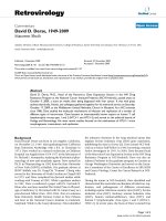
Limits Monitoring
Monitoring Limit
A monitoring limit divides the possible range of a parameter’s value into two parts, the upper
zone and the lower zone. At any time the monitored parameter is considered to be in one and
only one of these zones. If the value of a parameter crosses the zone boundary in either
direction a MonitoringLimitZoneTransition event is generated (see Figure 1).
12
IPC-2546 with Amendment 1
January, 2003
Maximum
UPPER ZONE
Event
UpperDeadBand
DEAD BAND
Event
LowerDeadBand
LOWER ZONE
Minimum
Figure 1 Zone Boundary Transition – Monitoring Limits
There is an area of overlap between the two zones called the dead band. The dead band is a key
concept of limits monitoring, especially for floating point variables. Its purpose is to prevent a
phenomenon known as chattering (the repeated changing of zones due to small, rapid
fluctuations in a parameter’s value while near the zone boundary).
In practice the value of a parameter must reach the opposite boundary of the dead band before a
zone transition can occur. Thus, if a parameter's value reaches the UpperDeadBand and moves
into the upper zone it will not return to the lower zone until the value falls back to the
LowerDeadBand.
The difference between UpperDeadBand and LowerDeadBand should normally be greater than
the typical amplitude of those fluctuations deemed insignificant. In some cases the width of the
dead band may be set to zero. The range of values of UpperDeadBand and LowerDeadBand are
limited by the following:
Maximum > UpperDeadBand >= LowerDeadBand > Minimum
Figure 2 illustrates the operation of the dead band when the following limit is used:
UpperDeadBand = 102, LowerDeadBand = 98, width of dead band = 4
110
108
Lower to
Upper Event
Lower to
Upper Event
106
Upper Dead Band
104
Value
102
Nominal Limit
100
98
96
Lower Dead Band
94
Upper to
Lower Event
90
88
Time
Figure 2 Example Graphing DeadBand Operation
13
IPC-2546 with Amendment 1
5.1.2
January, 2003
Abstract Model of Screen Printer Item(s), Lane(s) and Zone(s)
Figure 3 shows an example comparing a two lane operation each having three separate Zones
that must be monitored.
Zone 3
Zone 2
Zone 1
Lane 2
Lane 1
Item(s)
Figure 3 Multiple Lane, Multiple Zone Example
5.1.3
Abstract Model of Screen Printer Subsystems (Single Lane, Single Zone)
Figures 4 and Figure 5 show the conditions of the screen printer system for a single lane, having
a single zone. Figure 4 is an exploded view; Figure 5 shows the details of the print operation.
Print Dispenser
Print Head
Stencil
Applicator(s)
Medium
Vision
System
Transport
Stencil
Cleaner
Tooling
Item
Table
Figure 4 Exploded View
14
IPC-2546 with Amendment 1
January, 2003
Figure 5 Print Operation View
5.1.4
5.1.4.1
Dictionary of Screen Printing Specific Attributes and Parameters
Screen Printing Recipe Parameters
The following table specifies the screen printing recipe parameters that may be adjusted during
screen
printer
operation.
Parameter
adjustments
will
be
reported
via
the
EquipmentParameterModified event’s Extensions element.
All parameters in the following table are defined using the Parameter element type.
nameId
Value Type
Description
BatchLimit
double
The number of items to print in one batch
CleaningFrequency
integer
The number of items to be printed
between each cleaning cycle
InspectionFrequency
integer
The number of items to be printed
between each inspection cycle
PrintMediumConditioningFrequency
integer
The number of items to be printed
between each print medium conditioning
cycle
PrintMediumDispenseFrequency
integer
The number of items to be printed
between each print medium dispense
cycle
PrintMediumDispenseSpeed
double
The linear speed of the print dispenser
FrontApplicatorPressureRecipe
double
The required force to be applied by the
front applicator
FrontApplicatorSpeedRecipe
double
The required linear speed of the front
applicator
FrontApplicatorAccelerationRecipe
double
The required acceleration of the front
applicator
RearApplicatorPressureRecipe
double
The required force to be applied by the
rear applicator
RearApplicatorSpeedRecipe
double
The required linear speed of the rear
applicator
15
IPC-2546 with Amendment 1
January, 2003
RearApplicatorAccelerationRecipe
double
The required acceleration of the rear
applicator
FrontApplicatorSeparationDistanceRecipe
double
The required separation distance between
the front applicator and stencil
FrontApplicatorSeparationSpeedRecipe
double
The required separation speed of the front
applicator from the stencil
FrontApplicatorSeparationAccelerationRecipe
double
The required separation acceleration of
the front applicator from the stencil
RearApplicatorSeparationDistanceRecipe
double
The required separation distance between
the rear applicator and stencil
RearApplicatorSeparationSpeedRecipe
double
The required separation speed of the rear
applicator from the stencil
RearApplicatorSeparationAccelerationRecipe
double
The required separation acceleration of
the rear applicator from the stencil
ItemSeparationDistanceRecipe
double
The required separation distance between
the item and stencil
ItemSeparationSpeedRecipe
double
The required separation speed of the item
from the stencil
ItemSeparationAccelerationRecipe
double
The required separation acceleration of
the item from the stencil
SeparationMode
String
(enumeration)
The order in which the Applicator and Item
separate after the print cycle is complete
ITEMTHENAPPLICATOR |
APPLICATORTHENITEM |
SIMULTANEOUS
XOffset
double
The fixed offset in the X direction required
to align the item with the print stencil
YOffset
double
The fixed offset in the Y direction required
to align the item with the print stencil
ThetaOffset
double
The fixed offset rotation required to align
the item with the print stencil
16
IPC-2546 with Amendment 1
5.1.4.2
January, 2003
Screen Printing Process Data Parameters
The following table specifies Screen Printing Process Data parameters. All parameters are
defined using the Parameter element type.
Parameter
Value Type
Description
XAlignment
double
The linear movement required in the X
direction to align the item with the print
stencil
YAlignment
double
The linear movement required in the Y
direction to align the item with the print
stencil
ThetaAlignment
double
The rotational movement required in the
Theta direction to align the item with the
print stencil
BoardStretch
double
The difference in fiducial separation on
the item versus the difference in fiducial
separation on the print stencil
MaxPrintMediumPresent
double
The maximum print medium present
reported by the inspection system
MinPrintMediumPresent
double
The minimum print medium present
reported by the inspection system
AvgPrintMediumPresent
double
The average print medium present
reported by the inspection system
FrontApplicatorPressureActual
double
The actual force applied by the front
applicator
FrontApplicatorSpeedActual
double
The actual linear speed of the front
applicator
FrontApplicatorAccelerationActual
double
The actual acceleration of the front
applicator
RearApplicatorPressureActual
double
The actual force applied by the rear
applicator
RearApplicatorSpeedActual
double
The actual linear speed of the rear
applicator
RearApplicatorAccelerationActual
double
The actual acceleration of the rear
applicator
FrontApplicatorSeparationDistanceActual
double
The actual separation distance between
the front applicator and stencil
FrontApplicatorSeparationSpeedActual
double
The actual separation speed of the front
applicator from the stencil
FrontApplicatorSeparationAccelerationActual
double
The actual separation acceleration of
the front applicator from the stencil
RearApplicatorSeparationDistanceActual
double
The actual separation distance between
the rear applicator and stencil
RearApplicatorSeparationSpeedActual
double
The actual separation speed of the rear
applicator from the stencil
RearApplicatorSeparationAccelerationActual
double
The actual separation acceleration of
the rear applicator from the stencil
17
IPC-2546 with Amendment 1
January, 2003
ItemSeparationDistanceActual
double
The actual separation distance between
the item and stencil
ItemSeparationSpeedActual
double
The actual separation speed of the item
from the stencil
ItemSeparationAccelerationActual
double
The actual separation acceleration of
the item from the stencil
ItemFiducial1Score
double
The score for item fiducial 1
ItemFiducial2Score
double
The score for item fiducial 2
ItemFiducial3Score
double
The score for item fiducial 3
StencilFiducial1Score
double
The score for stencil fiducial 1
StencilFiducial2Score
double
The score for stencil fiducial 2
StencilFiducial3Score
double
The score for stencil fiducial 3
Temperature
double
The internal temperature of the screen
printer
Humidity
double
The internal humidity of the screen
printer
CycleTime
double
The time elapsed from a item being
received from up-line to the same item
being released to down-line.
5.1.4.3
Screen Printing Attributes
Attribute Name
Attribute Type
Description
vendorWarningCode
string
Vendor specific warning code
transitionType
String
(enumeration)
Indicates the direction in which a monitoring
limit was crossed.
LOWERTOUPPER | UPPERTOLOWER
upperDeadBand
double
The upper boundary of the dead band for a
monitoring limit
lowerDeadBand
double
The lower boundary of the dead band for a
monitoring limit
18
IPC-2546 with Amendment 1
5.1.5
January, 2003
Screen Printing Dictionary of Nested Elements
5.1.5.1
Element: MonitoringLimitZoneTransition
Description: An element containing the details of a monitoring limit zone transition.
Attribute Name
Attribute Type
Description
Occurrence
nameId
string
Name of the parameter that has crossed
the monitoring limit
1-1
transitionType
String
(enumeration)
Indicates the direction in which the
monitoring limit was crossed.
1-1
LOWERTOUPPER | UPPERTOLOWER
upperDeadBand
double
The upper boundary of the dead band
for the monitoring limit
0-1
lowerDeadBand
double
The lower boundary of the dead band
for the monitoring limit
0-1
Parameter
See 4.4.4
Details of the parameter that has
crossed the monitoring limit
0-1
transitionType = "LOWERTOUPPER"
upperDeadBand = "51.0"
lowerDeadBand = "49.0">
value = "51.1"
units = "Celsius"
minimum = "0.0"
maximum = "110.0"
/>
</MonitoringLimitZoneTransition>
5.1.5.1.1
Monitoring Limit Ids for MonitoringLimitZoneTransition Message
The following table lists the MonitoringLimitZoneTransition name Ids that are applicable to
screen printing
nameId
Attribute Type
XAlignment
string
YAlignment
string
ThetaAlignment
string
BoardStretch
string
MaxPrintMediumPresent
string
MinPrintMediumPresent
string
AvgPrintMediumPresent
string
FrontApplicatorPressureActual
string
FrontApplicatorSpeedActual
string
19