Ipc 2547 eng american national standards institute (ansi)
Bạn đang xem bản rút gọn của tài liệu. Xem và tải ngay bản đầy đủ của tài liệu tại đây (1.23 MB, 56 trang )
ASSOCIATION CONNECTING
ELECTRONICS INDUSTRIES ®
IPC-2547
Sectional Requirements
for Shop-Floor Equipment
Communication Messages
(CAMX) for Printed Circuit
Board Test, Inspection
and Rework
Endorsed by the National
Electronics Manufacturing
Initiative (NEMI)
IPC-2547
January 2002
A standard developed by IPC
3000 Lakeside Drive, Suite 309S, Bannockburn, IL 60015-1219
Tel. 847.615.7100 Fax 847.615.7105
www.ipc.org
The Principles of
Standardization
In May 1995 the IPC’s Technical Activities Executive Committee adopted Principles of
Standardization as a guiding principle of IPC’s standardization efforts.
Standards Should:
• Show relationship to Design for Manufacturability
(DFM) and Design for the Environment (DFE)
• Minimize time to market
• Contain simple (simplified) language
• Just include spec information
• Focus on end product performance
• Include a feedback system on use and
problems for future improvement
Notice
Standards Should Not:
• Inhibit innovation
• Increase time-to-market
• Keep people out
• Increase cycle time
• Tell you how to make something
• Contain anything that cannot
be defended with data
IPC Standards and Publications are designed to serve the public interest through eliminating
misunderstandings between manufacturers and purchasers, facilitating interchangeability and
improvement of products, and assisting the purchaser in selecting and obtaining with minimum
delay the proper product for his particular need. Existence of such Standards and Publications
shall not in any respect preclude any member or nonmember of IPC from manufacturing or selling products not conforming to such Standards and Publication, nor shall the existence of such
Standards and Publications preclude their voluntary use by those other than IPC members,
whether the standard is to be used either domestically or internationally.
Recommended Standards and Publications are adopted by IPC without regard to whether their
adoption may involve patents on articles, materials, or processes. By such action, IPC does
not assume any liability to any patent owner, nor do they assume any obligation whatever to
parties adopting the Recommended Standard or Publication. Users are also wholly responsible
for protecting themselves against all claims of liabilities for patent infringement.
IPC Position
Statement on
Specification
Revision Change
It is the position of IPC’s Technical Activities Executive Committee (TAEC) that the use and
implementation of IPC publications is voluntary and is part of a relationship entered into by
customer and supplier. When an IPC standard/guideline is updated and a new revision is published, it is the opinion of the TAEC that the use of the new revision as part of an existing
relationship is not automatic unless required by the contract. The TAEC recommends the use
of the latest revision.
Adopted October 6. 1998
Why is there
a charge for
this standard?
Your purchase of this document contributes to the ongoing development of new and updated
industry standards. Standards allow manufacturers, customers, and suppliers to understand one
another better. Standards allow manufacturers greater efficiencies when they can set up their
processes to meet industry standards, allowing them to offer their customers lower costs.
IPC spends hundreds of thousands of dollars annually to support IPC’s volunteers in the
standards development process. There are many rounds of drafts sent out for review and
the committees spend hundreds of hours in review and development. IPC’s staff attends and
participates in committee activities, typesets and circulates document drafts, and follows all
necessary procedures to qualify for ANSI approval.
IPC’s membership dues have been kept low in order to allow as many companies as possible
to participate. Therefore, the standards revenue is necessary to complement dues revenue. The
price schedule offers a 50% discount to IPC members. If your company buys IPC standards,
why not take advantage of this and the many other benefits of IPC membership as well? For
more information on membership in IPC, please visit www.ipc.org or call 847/597-2872.
Thank you for your continued support.
©Copyright 2002. IPC, Bannockburn, Illinois. All rights reserved under both international and Pan-American copyright conventions. Any
copying, scanning or other reproduction of these materials without the prior written consent of the copyright holder is strictly prohibited and
constitutes infringement under the Copyright Law of the United States.
IPC-2547
ASSOCIATION CONNECTING
ELECTRONICS INDUSTRIES ®
CAMX
– TEST
Sectional Requirements
for Shop-Floor Equipment
Communication Messages
(CAMX) for Printed Circuit
Board Test, Inspection
and Rework
A standard developed by the Inspection and Test XML Schema Formatting Task
Group (2-13c) of the Shop Floor Communications Subcommittee (2-13) of IPC.
The IPC-2547 standard defines an the XML encoding schema, applied for the
specific printed board assembly inspection and test equipment including manual
visual inspection stations (MVI), automatic optical inspection stations (AOI),
automatic laser inspection stations (ALI), manual x-ray (MXI), automatic x-ray
inspection stations (AXI), flying-probe in-circuit test stations (FPT), bed-of-nails
in-circuit stations (ICT) and functional test stations (FNT).
This project was initiated by the NEMI Plug-and-Play Factory Project which
established proof of concept. After completion, the project leaders recommended
standardization by IPC under the ANSI rules and procedures.
March 20, 2002
Users of this standard are encouraged to participate in the
development of future revisions.
Contact:
IPC
3000 Lakeside Drive, Suite 309S
Bannockburn, Illinois
60015-1219
Tel 847 615.7100
Fax 847 615.7105
IPC-2547
January 2002
Acknowledgment
Any Standard involving a complex technology draws material from a vast number of sources. While the principal members
of the Inspection and Test XML Schema Formatting Task Group (2-13c) of the Shop Floor Communications Subcommittee
(2-13) are shown below, it is not possible to include all of those who assisted in the evolution of this standard. To each of
them, the members of the IPC extend their gratitude.
Shop Floor Communications
Subcommittee
Inspection and Test XML
Schema Formatting Task Group
Technical Liaison of the
IPC Board of Directors
Chair
Allan Fraser
GenRad Inc.
Chair
Bob Neal
Agilent Technologies
Dr. William Beckenbaugh
Sanmina
Inspection and Test XML Schema Formatting Task Group
Tom Baggio, Panasonic Factory
Automation Company
Mike Hamblin, GenRad Inc.
Cord Burmeister, Siemens Dematic
AG
Dave Kerem, Camalot Division,
Speedline Technologies
Tom Dinnel, Universal Instruments
Miles Moreau, KIC
Mike Rogers, DEK Printing
Machines Ltd.
Andrew D. Dugenske, Georgia
Institute of Technology
Dave J. Morris, Nortel Networks
Hannu Ronkainen, JOT Automation
Hitoshi Nakamura, Matsushita
Electric Industrial Co. Ltd.
Bob Voitus, Celestica Inc.
Allan Fraser, GenRad Inc.
Frank Gearhart, Assembleon
Bob Neal, Agilent Technologies
Yoshiyuki Hattori, Matsushita
Electric Industrial Co. Ltd.
Andy Oughton, DEK Printing
Machines Ltd.
Nam Hoang, KIC
Jim Perilli, MPM Division, Speedline
Technologies
Jari Pirkola, JOT Automation
Mark Williams, Motorola
A special note of thanks goes to the following individuals for their dedication to bringing this project to fruition. We would
also like to highlight those individuals who were involved with the initial NEMI program concept and made major contributions to the development of the standard.
Allan Fraser, GenRad, Incorporated
Bob Voitus, Celestica, Inc.
Dave Morris, Nortel Networks
Robert E. Neal, Agilent Technologies
Andy Dugenske, Georgia Institute of
Technology
Mark Williams, Motorola
ii
Table of Contents
1
Scope ............................................................................................................................ 1
2
1.1 Interpretation ........................................................................................................ 1
Applicable documents .................................................................................................... 1
3
General Requirements ................................................................................................... 2
4
3.1
3.2
3.3
Test
Terms and Definitions............................................................................................ 2
Date and Time Notation ......................................................................................... 4
CAMX Compliance ................................................................................................ 4
and Inspection Specific Event Messages ................................................................. 5
4.1
5
Management Event - ProcessSessionStart............................................................. 6
4.1.1 Event: ProcessSessionStart ....................................................................... 6
4.1.2 Element: Product ....................................................................................... 7
4.1.3 Element: Operator ..................................................................................... 7
4.1.4 Element: Entity .......................................................................................... 7
4.1.5 Element: Recipe ........................................................................................ 8
4.1.6 Element: RecipeModule ............................................................................. 8
4.1.7 Element: FixtureTooling ............................................................................. 8
4.2 Event: ProcessSessionEnd .................................................................................... 9
4.3 Event: InspectionFrame ....................................................................................... 10
4.3.1 Element: Region ...................................................................................... 11
4.3.2 Element: Orientation ................................................................................ 11
4.3.3 Element: Base64Encoding ....................................................................... 11
4.4 Event: ItemProcessStatus.................................................................................... 12
4.4.1 Element: ItemEventCount ........................................................................ 13
4.5 Event: ProcessStepStatus ................................................................................... 13
4.5.1 Element: Error ......................................................................................... 14
4.5.2 Element: Symptom................................................................................... 15
4.5.3 Element: Indictment ................................................................................. 15
4.5.4 Element: RegionOfInterest ....................................................................... 16
4.5.5 Element: Point ......................................................................................... 16
4.5.6 Element: Measurement ............................................................................ 17
4.5.7 Element: MeasuredNumeric ..................................................................... 17
4.5.8 Element: MeasuredOctet.......................................................................... 17
4.5.9 Element: ExpectedNumeric ...................................................................... 18
4.5.10 Element: ExpectedOctet .......................................................................... 19
4.5.11 Element: Signal ....................................................................................... 19
4.5.12 Element: Component ............................................................................... 20
4.6 Event: ItemRepair ............................................................................................... 22
4.6.1 Element: DefectDetail .............................................................................. 22
4.6.2 Element: RepairAction ............................................................................. 23
Event Extensions ......................................................................................................... 24
6
Event Sequences ......................................................................................................... 24
6.1
6.2
Test Sequences .................................................................................................. 24
Inspection Sequences ......................................................................................... 24
iii
7
IPC-2547 XML Schema Definition ................................................................................. 25
7.1
7.2
7.3
7.4
7.5
7.6
ProcessSessionStart ........................................................................................... 25
ProcessSessionEnd ............................................................................................ 28
InspectionFrame ................................................................................................. 29
ItemProcessStatus .............................................................................................. 31
ProcessStepStatus .............................................................................................. 33
ItemRepair .......................................................................................................... 38
Appendix A – Acronym Definitions ....................................................................... 40
Appendix B – Example Symptoms ....................................................................... 41
Appendix C – Example Indictments ..................................................................... 42
Appendix C – Example Indictments ..................................................................... 42
Appendix D – Example Repair Actions................................................................. 44
Appendix E – Example Indictment/Symptom Categories....................................... 45
Appendix F – Suggested Component Types......................................................... 46
Appendix G – Suggested Component Package Types .......................................... 47
Appendix H – Example Package Lead Types ....................................................... 48
Appendix I - IPC Web-based Standards (IPC25XX)............................................ 49
iv
IPC-2547
January 2002
Sectional Requirements for Shop-Floor Equipment Communication
Messages (CAMX) for Printed Circuit Board Test, Inspection and Rework
Introduction
Factory Information Systems (FIS) form the nervous system of an enterprise, analyzing data and
delivering information to the machines and people who need to make information-based
decisions. These systems provide a bi-directional flow of information between the factory floor
and the rest of the enterprise and beyond.
The CAMX standards (IPC 254X) are designed to foster application integration and shop floor
equipment communications based on XML. It assumes that application programs (including
equipment interfaces) are distinct entities, and application integration takes place using a loosely
coupled, message-passing approach.
There is no need for a common object model,
programming language, network protocol, persistent storage mechanism or operating system for
two applications to exchange XML messages formatted using the CAMX standards. The two
applications simply need to be able to format, transmit, receive and consume a standardized
XML message.
1 Scope
This document describes event message content and an XML encoding scheme, that enables a
detailed definition of messages in the domain of electronics inspection, test and repair/rework
(i.e. product and process quality). These messages are to be encoded at a level appropriate to
facilitate interoperability in the factory shop floor equipment and information system integration
process.
1.1 Interpretation
"Shall", the emphatic form of the verb, is used throughout this standard whenever a requirement
intended to express a provision that is mandatory. Deviation from a shall requirement is not
permitted, and compliance with the XML syntax and semantics shall be followed without
ambiguity, or the insertion of superfluous information.
The words "should" and "may" are used whenever it is necessary to express non-mandatory
provisions.
"Will" is used to express a declaration of purpose.
To assist the reader, the word shall is presented in bold characters.
2 Applicable documents
The following documents contain provisions that, through reference in this text, constitute
provisions of this standard. All documents are subject to revision. Parties who make agreements
based on this standard are encouraged to investigate the possibility of applying the most recent
editions of the documents indicated below.
IPC-T-50
Terms and Definitions for Interconnecting and Packaging Electronic Circuits
IPC 2500 Virtual Factory Information Interchange Framework definitions
1
IPC-2547
January 2002
IPC 2511 Generic Computer Aided Manufacturing (GenCAM) descriptions for Printed Circuit
Boards and Printed Board Assembly
IPC 2541 Generic Requirements for Electronics
Communication Messages (CAMX)
Manufacturing
Shop-Floor
Equipment
IPC-2546 Sectional Requirements for Shop-Floor Equipment Communication Messages (CAMX)
for Printed Circuit Board Assembly
W3C
Date-time format standard
3 General Requirements
The requirements of IPC-2541 are a mandatory part of this standard. That document describes
the generic requirements for the CAMX format.
3.1 Terms and Definitions
The definition of all terms used herein shall be as specified in IPC-T-50, and the following:
Assembly
An electronic product consisting of a printed circuit board or boards, attached electronic and
mechanical components with associated connectors and cabling.
Base-64
A method of encoding binary data into a restricted, printable ASCII characters subset. This
method is used by the inspection systems for encoding their binary image format, such as .tif,
jpg, and .bmp.
Board
A single instance of a printed circuit. One circuit image of a fabrication panel. The foundation of
an electronic printed circuit assembly.
Component
A single instance of a part package. Identified by an alpha-numeric designator, each of these
will have a unique location on a circuit assembly.
Defect
An unacceptable deviation from a norm.
Event
A process action or trigger of significance. Also a term used in this standard as synonymous
with message records generated upon the event occurrence.
Fault
The detected manifestation of a defect.
Frame
An instance of a captured optical, x-ray, or infra-red picture, image or other artifact facsimile of a
circuit board or assembly. A Frame may be of a relatively small geometry or it may represent an
entire assembly.
2
IPC-2547
January 2002
Image
A single board or assembly circuit instance typically used to identify one member of a
homogeneous or heterogeneous panel, but not limited to that.
Item
An identifiable and traceable product or product component instance.
Indictment
A defect condemnation identified during human or automated inspection or test.
Octet
A measured or expected value expressed as an 8-bit byte. Measured and expected values that
are not necessarily numeric in nature (e.g. character strings) are expressed and compared as
octets.
Panel
An electronic assembly consisting of multiple circuit images. Homogeneous panels are defined
as having multiple of the same circuit image revision and assembly (Bill of Materials) revision.
Heterogeneous panels are defined a having more than one circuit image and/or more than one
assembly revision.
Inspection
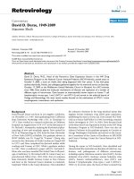
A process relating to one or more regions-of-interest of a board or an assembly.
Region Of Interest (ROI)
An area of focus in or on an electronic assembly pertinent to inspection.
Frame
Image
(Board)
Region of
Interest
Panel
Figure 1 Inspection Frame and Inspection Region of Interest
3
IPC-2547
January 2002
Signal
An electrically-common logical net or physical conductor or connection.
Station
A uniquely identifiable, task-specific work area of a manufacturing environment.
Stage
A uniquely identifiable task within the sequence of manufacturing steps for electronic
assemblies.
Symptom
Description of an element of evidence of a fault or defect.
Termination
A lead, pin, ball, leg or other conductive connection between a component package and the
circuit board.
3.2 Date and Time Notation
All 2540 standards shall use the World Wide Web consortium (W3C) date time standard. This
standard shall use the Complete Date plus Hours, Minutes, Seconds, and a decimal fraction of a
second and Time Zone Designator. Two decimal places will be used in order to represent time
down to a hundredth of a second. For additional information on date and time, see web page:
/>3.3 CAMX Compliance
The IPC-2501 document defines a message packet structure. The IPC-2541 document defines a
set of Equipment, Recipe, Item, and Operator events and related message formats. All test,
inspection and repair stations that comply with the IPC-2547 standards shall also comply with
the event messages contained in the IPC-2541 standard as well as those events that are
described in this document. All event messages shall be formatted in compliance with the IPC2501 message packet structure. For consistency in XML style, all CAMX XML Element and
attribute names shall be in mixed-case with Element names beginning with an upper case letter
and attribute names beginning with a lower case letter. XML Elements are order specific and
shall appear in the order prescribed in the XML schema definitions.
4
IPC-2547
January 2002
4 Test and Inspection Specific Event Messages
The figure below illustrates the relationships and cardinality of the key event elements.
ProcessSessionStart
sessionId
ItemProcessStatus
itemProcessId
Signal
One or more
ProcessStepStatus
events can be
associated with a
single
ItemProcessStatus
signalId
One or more Signals,
and/or Components,
may be analyzed for
one ProcessStepStatus
ProcessStepStatus
processStepId
Component
designator
A process
step may
result in zero
or more
Indictments
or Symptoms
RepairAction
Indictment
repairKey
indictmentId
Zero or more
inspection
regions may
be used to
determine the
result for a
single
ItemProcess
Step
One or more
RepairActions may
be associated with a
single ItemRepair
ItemRepair
symptomId
repairId
Zero or more
Measurements
may be used to
determine a single
ProcessStepStatus
Measurement
regionId
An
InspectionFrame
can have multiple
regions of interest.
A single ItemRepair
can be associated
with one or more
Indictment or
Symptom
Symptom
RegionOfInterest
Zero or more
Signals, and/or
Components
may be
associated with
a single
RepairAction
measurementId
Zero or more
measurements may be
used to analyze a
single RegionOfInterest
A RetionOfInterests
can reference one
or more
InspectionFrames
InspectionFrame
frameId
Figure 2 Key Event Object Relationships
5
IPC-2547
January 2002
Though the events are asynchronous, the relationships are linked using identifiers and identifier
references for grouping the event records. Each session has an identifier that shall be unique
across at least the reporting domain. The recommendation is to use a date-time in conjunction
with a MAC or IP address, GUID or Java-style organization package path. For example:
•
•
Network address and date-time ("15.11.9.54-2000-08-05T10:04:31.20+0800")
Enterprise Id and date-time ("com.ourco.mch2-2000-08-05T10:04:31.20+0800")
This identifier is then referenced in each ItemProcessStatus There is one ItemProcessStatus for
one execution of the test or inspection program. In turn, each ItemProcessStatus has an
indentifier unique within the reporting domain that is referenced in the ProcessStepStatus event
for each step of the test or inspection program. Similarly each supporting inspection or test step
has an identifier that is unambiguous within the test or inspection program’s sequencing.
Indictments or symptoms of failing test steps are also unabiguously identified, enabling
association with repair events and repair actions.
The tables in this section define the event message attributes that are appropriate for test,
inspection, and repair/rework functions. These events are necessary for tracking product and
process quality as well as enabling identification and intelligent correlation of fault signatures to
effective repair actions. The right-most column (labeled Occ) indicates the expected number of
occurrences (cardinality) of each attribute or element. 0-1 indicates an optional field. 1-1
indicates a single mandatory field. 0-n indicates any number, including zero. 1-n indicates at
least one.
4.1 Management Event - ProcessSessionStart
In recognition that there is a need for information to be shared between factory equipment and
processes this event message has been defined to meet this need. There are typically many
items processed during one session. Consider this message as an event separator that can be
triggered by the equipment itself or by a change in its environment, including a new operator, a
shift change, a change in the product or in the program/recipe.
4.1.1 Event: ProcessSessionStart
Description: The ProcessSessionStart record provides information regarding the product,
process, location and environment.
Attribute Name
Attribute Type
Description
Occ
dateTime
dateTime
Date and time of the event
1-1
sessionId
string
Domain unique identifier of this process session
1-1
Product
Element
Identifies the type, lot, batch etc. of the product
1-1
Entity
Element
Identifies the location and enterprise
1-1
shift
string
Identify the work interval.
0-1
Recipe
Element
Identifies the process program, model, best
practices or algorithms
0-n
Operator
Element
Equipment operator identifier
0-n
FixtureTooling
Element
Identifies the test fixture(s) if applicable
0-n
6
IPC-2547
January 2002
4.1.2 Element: Product
Description: The Product element uniquely describes the item and its groupings.
Attribute Name
Attribute Type
Description
Occ
itemType
string
Product type id
1-1
itemClass
string
Identify the product classification such as
system, assembly, board,
0-1
boardRevision
string
Identify the board layout revision
0-1
assemblyRevision
string
Identify the assembly version (i.e. bill of
materials)
0-1
workOrder
string
Identify the product work order
0-1
batch
string
Identify the product batch
0-1
lot
string
Identify the product lot
0-1
count
positiveInteger
The number of product in the lot or batch
0-1
4.1.3 Element: Operator
Description: The Operator element shall contain a unique identifier for the operator such as
their employee number or social security number, and may also contain a personal identifier
such as the person's name, nickname or logon name.
Attribute Name
Attribute Type
Description
Occ
employeeId
string
Employee number, login name or internal identifier
1-1
givenName
string
Employee's first name
0-1
familyName
string
Employee's last name
0-1
4.1.4 Element: Entity
Description: The Entity element uniquely describes the equipment or process station.
Attribute Name
Attribute Type
Description
Occ
stationId
string
Process station identifier unique to the domain
1-1
stage
string
(enumerated)
Process step. One of: MVI | ALI | AOI | MXI | AXI
| MDA | FPT | ICT | FNT | INT | SYS | OLT
1-1
stationRevision
string
Identify the station’s hardware revision if
applicable
0-1
subStage
string
Additional information regarding the stage, station
or processing.
0-1
line
string
Identifier for this manufacturing line or cluster
0-1
building
string
Identify the building
0-1
site
string
Identify the site or location
0-1
enterprise
string
Identify the company
0-1
7
IPC-2547
January 2002
4.1.5 Element: Recipe
Description: The Recipe element uniquely identifies the recipe, program, algorithms or best
practices being executed at the station or specified station zones and/or lanes. The attributes
zoneList and laneList are defined using the XML string list syntax specified as a single quoted
string containing white-space (e.g. SPACE, TAB ) separated, alpha-numeric character groups.
Attribute Name
Attribute Type
Description
Occ
recipeId
string
Identifies the name of the program
1-1
revision
string
Identifies the revision of the program
1-1
zoneList
string (list)
Identifies the zone(s) executing this recipe
0-1
laneList
string (list)
Identifies the lane(s) executing this recipe
0-1
RecipeModule
Element
Identifies the files or individual parts of a multiple
part recipe
0-n
4.1.6 Element: RecipeModule
Description: The RecipeModule element uniquely identifies a single component of the recipe,
program, algorithms or best practices being executed at the station and identifies its type.
Attribute Name
Attribute Type
Description
Occ
moduleId
string
Identifies the name of the recipe part
1-1
revision
string
Identifies the revision of the recipe part if
applicable
0-1
type
string
(enumerated)
Identifies the entry type as one of ALGORITHM |
CONFIGURATION | DOCUMENTATION |
EXECUTIVE | FIRMWARE | LIMITS | SEQUENCE
| SETUP
0-1
4.1.7 Element: FixtureTooling
Description: The FixtureTooling element uniquely describes the test fixture and can be used to
track its actuation count for probing accuracy and maintenance purposes.
Attribute Name
Attribute Type
Description
Occ
fixtureId
string
Identify the test fixture
1-1
revision
string
Identify the revision of the fixture
1-1
serialNumber
string
Identify the particular fixture instance
0-1
type
string
Identify the fixture type or function
0-1
8
IPC-2547
January 2002
sessionId="NewCo3070-2-2000-08-05T10:04:31.20+0800"
shift="FIRST">
givenName="Jane"
familyName="Wilson"/>
stage="ICT"
line="3"
building="B6"
site="Hillsboro"
enterprise="CPUCo"/>
revision="3"
zoneList="3 4 5"
laneList="1 2"/>
revision="A"/>
boardRevision="B-20000512"
assemblyRevision="4"
workOrder="Cpq4592-002"
batch="12"
count="144"/>
</ProcessSessionStart>
4.2 Event: ProcessSessionEnd
Description: The ProcessSessionEnd record is optional, and can be used as the companion to
the ProcessSessionStart record and serve to close the process session.
Attribute Name
Attribute Type
Description
Occ
dateTime
dateTime
Date and time of the event
1-1
sessionId
string
Globally unique identifier of this process session
1-1
sessionId="NewCo3070-2-2000-08-05T10:04:31.20+0800"
/>
9
IPC-2547
January 2002
4.3 Event: InspectionFrame
Description: An image frame captured for analysis.
The InspectionFrame message describes an inspection frame, uniquely identifying it and
providing its size and location in relationship to the board origin. The data payload may include
the base-64 encoded image file (e.g., gif, tif, jpg, png) binary. There are typically many
InspectionFrame events per item (board, panel or assembly).
Attribute Name
Attribute Type
Description
Occ
dateTime
dateTime
Date and time of the event
1-1
itemInstanceId
string
Item instance identifier
1-1
sessionRef
string
References the session in which this event
occurred
1-1
itemProcessRef
string
References the process that captured the frame
1-1
frameId
string
Unique identifier for this frame for later
reference
1-1
Region
Region Element
Identify the frame region and orientation with
respect to the board origin.
1-1
imageId
string
Identify the board image if panelized or a single
item of a multiple item test grouping.
0-1
frameStatus
string
(enumerated)
PASSED | FAILED Frame either contains zero
failing regions-of-interest (PASSED) or contains
one or more failing regions (FAILED).
0-1
layer
string
Identify board surface or layer of the frame if
applicable. This can be the slice of an x-ray
inspection or absent for multiple-frame x-ray
image synthesis.
0-1
Base64Encoding
Base64 Element
Encoded frame element
0-1
10
IPC-2547
January 2002
4.3.1 Element: Region
Description: A rectangular or circular area definition. Point1X and point1Y attributes are always
required. If the point2X and point2Y attributes are present then the region is analyzed as
rectangular. If point2X and point2Y are not present then the diameter attribute shall be present
and the region is analyzed as circular.
Attribute Name
Attribute Type
Description
Occ
units
string
(enumerated)
Coordinate units (INCH | MM | PIXEL)
1-1
point1X
double
The region origin X value
1-1
point1Y
double
The region origin Y value
1-1
point2X
double
The opposite corner X value if rectangular
0-1
point2Y
double
The opposite corner Y value if rectangular
0-1
diameter
double
The diameter if a circular region
0-1
decade
double
Unit multiplier in powers of 10 (default is 0).
0-1
Orientation
Element
Rotation of the region vs. the board.
0-1
4.3.2
Element: Orientation
Description: The Orientation element describes the rotation (theta) of an InspectionFrame
region with respect to its parent board or the rotation of a RegionOfInterest with respect to its
InspectionFrame.
Attribute Name
Attribute Type
Description
Occ
value
double
Rotation value
1-1
units
string
(enumerated)
Rotation units (DEGREES|RADIANS)
1-1
4.3.3 Element: Base64Encoding
Description: The Base64Encoding element identifies the MIME type of the binary and its
encoding. If the binary is decoded at its destination and written to the file system it is given the
name and the suffix associated with the type.
Attribute Name
Attribute Type
Description
Occ
name
string
File name
1-1
mimeType
string
Frame MIME type (suffix)
1-1
encoding
string
Base-64 encoded frame
1-1
itemInstanceId="66540A00343"
sessionRef=="NewCo3070-2-2000-08-05T10:04:31.20+0800"
11
IPC-2547
January 2002
itemProcessRef="20111954-2000080510043120+08"
imageId="3"
frameId="382"
frameStatus="FAILED"
layer="2">
point1Y="3000"
point2X="2750"
point2Y="3750"
units="INCH"
decade="-3">
<Orientation value="90" units="DEGREES"/>
</Region>
mimeType="JPG"
encoding="XXXXXXXXXX- Base 64 Encoded Binary Image -XXXX"
/>
</InspectionFrame>
4.4 Event: ItemProcessStatus
Description: Processing of an item has completed, and the process task issues an overall status
for the processed item.
This message reports the overall status of a complete test or inspection of a product item. This
message is intended to satisfy those applications that analyze product quality using such
measures as first pass yield. If the item arrived at the equipment but was passed through and not
processed then a status of NOTEST is reported. If the equipment's test or inspection process
was interrupted then a status of ABORTED is reported. If an equipment hardware or software
error occurs that precludes a successful completion of the process then a status of ERROR is
reported. If any of the individual test or inspection steps produced a failing status then the overall
status shall be FAILED. Otherwise the overall status shall be PASSED. The exception to this is
when a known-good item is being processed for the purpose of equipment calibration or program
verification. To identify these process step executions and prevent the skewing of the statistical
analysis of the process, the status should be set to KNOWNGOOD.
ItemEventCount element should be included within the ItemProcessStatus event and is
generated for purposes of data integrity. Due to the nature of network transport of IPC-2547
event messages, this record is provided to assure that the client has received all of the
messages that were sent regarding the processing of an item at a test or inspection stage. This
message is for information purposes only. There is no recommendation of appropriate action to
be taken when the number of event messages received does not match the count in the
ItemEventCount.
Attribute Name
Type
Description
Occ
dateTime
dateTime
Date and time of the event
1-1
itemInstanceId
string
Item instance identifier
1-1
sessionRef
string
A reference to the unique process session
identifier
1-1
12
IPC-2547
January 2002
itemProcessId
string
An identifier for a single process execution that
is unique within the physical and temporal
domains of the session.
1-1
status
string
(enumerated)
NOTEST | PASSED | FAILED | ABORTED |
ERROR | KNOWNGOOD
1-1
mode
string
(enumerated)
ENGINEERING | CALIBRATION | PRODUCTION
0-1
imageId
string
Identify the board image if panelized or a single
item of a multiple item test grouping.
0-1
itemParentId
string
Identify parent of instance if panelized
0-1
ItemEventCount
Element
Provides a count of published events associated
with the processing of this item.
0-n
comment
string
Any additional information at the whole process
level.
0-1
4.4.1 Element: ItemEventCount
Description: The count of IPC-2547 events associated with this item and process.
Attribute Name
Attribute Type
Description
Occ
eventType
string (enumerated)
INSPECTIONFRAME |
PROCESSSTEPSTATUS
1-1
count
nonNegativeInteger
The number of event records sent
1-1
itemInstanceId="66540A00343"
sessionRef="NewCo3070-2-2000-08-05T10:04:31.20+0800"
itemProcessId="20111954-2000080510043120+08"
status="PASSED"
mode="PRODUCTION"
imageId="4" >
<ItemEventCount eventType="INSPECTIONFRAME" count="347"/>
<ItemEventCount eventType="PROCESSSTEPSTATUS" count="6492"/>
</ItemProcessStatus>
4.5 Event: ProcessStepStatus
Description: An inspection or measurement step has been executed and a resulting status for
the individual step has been determined.
Execution of a Measurement or Inspection process step triggers the issuing of a
ProcessStepStatus event. This step status event shall be unambiguously identified within the
test or inspection program execution (e.g. processStepId or processStepId + sequence) and
shall provide a reference to the overall process event and to the session event.
If the process step is incomplete due to temporal or equipment limit conditions then the
ProcessStepStatus shall be NOTEST. If an equipment error (e.g. fiducial, barcode) occurs that
precludes a successful completion of the step then a status of ERROR shall be reported.
Otherwise the ProcessStepStatus shall be PASSED or FAILED. If the status is FAILED then
13
IPC-2547
January 2002
one or more Indictment or Symptom elements may be included in the event.
Each
ProcessStepStatus event may reference one or more RegionOfInterest or Measurement events
that contributed to the status, and may also contain one or more Symptom and/or Indictment
elements as well as associated Component or Signal elements.
Attribute Name
Attribute Type
Description
Occ
dateTime
dateTime
Date and time of the event
1-1
itemInstanceId
string
Item instance identifier
1-1
sessionRef
string
References the session for this event
1-1
itemProcessRef
string
References the overall process issuing the
status
1-1
processStepId
string
Identify the process step leading to the status.
1-1
status
string
(enumerated)
PASSED | FAILED | NOTEST | ERROR
1-1
imageId
string
Identify the board image if panelized or a single
item of a multiple item test grouping.
0-1
sequence
positiveInteger
Execution/presentation order or disambiguation
0-1
comment
string
Additional free-format information
0-1
Error
Element
Additional information supporting a status of
ERROR
0-n
Symptom
Element
Identify an observed anomaly if applicable
0-n
Indictment
Element
Identify the defect type if applicable
0-n
RegionOfInterest
Element
Inspection region(s) associated with this step
0-n
Measurement
Element
Measurement(s) associated with this step
0-n
Component
Element
Associated component(s)
0-n
Signal
Element
Associated signal network(s)
0-n
4.5.1 Element: Error
Description: This element is sent by a piece of equipment when it cannot process an item to
produce a meaningful PASS/FAIL status. This event differs from the IPC-2541 EquipmentError
in that it does not halt the equipment and does not require operator or host intervention.
Attribute Name
Attribute Type
Description
Occ
errorId
string
Error identifier
1-1
description
string
The error symptom or other diagnostic
information.
0-1
recipeRef
string
Reference the recipe being executed
0-1
moduleRef
string
Reference the recipe module if applicable
0-1
recipeStep
string
Identify the recipe step or command
0-1
lane
string
Identify the lane
0-1
zone
string
Identify the zone
0-1
14
IPC-2547
January 2002
4.5.2 Element: Symptom
Description: This element provides detailed information on a measured or observed fault. The
symptomKey attribute should be specific. (See Appendix-B for a suggested list of symptom
keys.) The confidence attribute value expresses a low (0) confidence to high (100) confidence in
the observation or measurement to identify a defect. The category attribute can provide a
keyword to be used for such functions as diagnostics, routing, closed loop quality.
Attribute Name
Attribute Type
Description
Occ
symptomId
string
Identifier for this symptom record with which to
associate one or more repair actions.
1-1
symptomKey
string
Identifies product or process faults (See
Appendix B)
1-1
category
string
Additional key, if known (See Appendix E)
0-1
description
string
Additional free format information (comment)
0-1
confidence
nonNegativeInteger
(100-0)
Relative confidence in the symptomKey
accuracy
0-1
MeasurementRef
Element
Reference to the Measurement Id(s) associated
with this event
0-n
RegionRef
Element
Reference to the RegionOfInterest Id(s)
associated with this event
0-n
4.5.3
Element: Indictment
Description: This element provides specific information supporting a failing ProcessStepStatus.
The indictmentKey attribute should be specific. (See Appendix-C for a suggested list of
indictment keys.) The priority attribute is expressed in a value from high (1) priority to an openended low priority (n) of the indictment. The confidence attribute value expresses a low (0)
confidence to high (100) confidence in the indictment. The category attribute can provide a
keyword to be used for such functions as diagnostics, routing, closed loop quality.
Attribute Name
Attribute Type
Description
Occ
indictmentId
string
Identifier for this indictment record with which to
associate one or more repair actions.
1-1
indictmentKey
string
Identifies product or process faults (See
Appendix C)
1-1
category
string
Additional key, if known. ( See Appendix E)
0-1
description
string
Additional free format information (comment)
0-1
priority
positiveInteger
Presentation of an unbounded priority of the
indictment where 1 = highest priority.
0-1
confidence
nonNegativeInteger
(100-0)
Relative confidence in the indictmentKey
accuracy
0-1
MeasurementRef
Element
Reference to the Measurement Id(s) that lead to
this indictment
0-n
RegionRef
Element
Reference to the RegionOfInterest Id(s) that lead
to this indictment.
0-n
15
IPC-2547
January 2002
4.5.4 Element: RegionOfInterest
Description: A sub-region of an item or an inspection frame.
Manual inspection can be of an item component, region or point. With automated inspection
technologies the imaging device (e.g. camera) captures a frame. One or more regions of interest
(ROI) of the frame(s), scan(s) or field(s)-of-view is analyzed. The RegionOfInterest element is
uniquely identified and describes one inspection region and the analysis that combines to justify
the ProcessStepStatus. The X and Y points describing the inspected region or location are
themselves elements containing a value in one of three units: millimeter (MM), inch (INCH) or
pixel (PIXEL). If an InspectionFrame is referenced then the location of the RegionOfInterest
shall be with relation to the InspectionFrame origin.
Attribute Name
Attribute Type
Description
Occ
regionId
string
Unique identifier for the inspection region
1-1
frameRef
string (list)
Reference to one or more frame elements
0-n
layer
string
Identify board surface or layer of the region.
0-1
status
string (enumerated)
Option to report (PASSED | FAILED) status of
the inspection of the point, region or component.
0-1
Region
Region Element
Identify the region of interest (ROI) dimensions
and orientation.
0-1
Point
Point Element
Identify an exact (X,Y) point of interest
0-1
Component
Component Element
Identify associated component or feature
inspected
0-1
4.5.5 Element: Point
Description: Provides an XY ordered pair with units and decade (order of magnitude).
Attribute Name
Attribute Type
Description
Occ
pointX
double
X Parameter value
1-1
pointY
double
Y Parameter value
1-1
units
string (enumerated)
Parameter units (MM | INCH)
1-1
decade
double
Unit multiplier in powers of 10 (default is 0).
0-1
16
IPC-2547
January 2002
4.5.6 Element: Measurement
Description: When the test or inspection of an item results in measured values, those
measurements are described using the Measurement event.
This is true whether the
measurement is a numeric value, a string value, or a bit sequence or an array of any of these.
Measured values shall be one of MeasuredNumeric or MeasuredOctet so that the values can be
reported and correctly parsed. Similarly, expected values shall be one of ExpectedNumeric or
ExpectedOctet.
Attribute Name
Attribute Type
Description
Occ
measurementId
string
Identify the measurement by a name unique
within this item process. (test program)
1-1
mode
string
Additional information about the measurement
result
0-1
type
string
Identify the type of measurement
0-1
sequence
positiveInteger
Identify the sequence number if applicable
0-1
status
string (enumerated)
Option to report (PASSED | FAILED) status.
0-1
MeasuredNumeric
Element
A numeric value measured
0-n
MeasuredOctet
Element
A string, byte or bit sequence value measured
0-n
ExpectedNumeric
Element
A numeric value and range expected.
0-n
ExpectedOctet
Element
A string, byte or bit sequence value expected
0-n
Component
Element
Identify associated component(s)
0-n
Signal
Element
Identify associated signal network(s)
0-n
4.5.7 Element: MeasuredNumeric
Description: Provides a numeric value.
Attribute Name
Attribute Type
Description
Occ
value
double
Parameter value
1-1
units
string
Units of measure
0-1
decade
double
Unit multiplier in powers of 10 (default is 0).
0-1
position
string (list)
Describe the positional location if the expression
is for a multidimensional array of values
0-1
4.5.8 Element: MeasuredOctet
Description: A measured string, byte or bit sequence value.
Attribute Name
Attribute Type
Description
Occ
value
string
Measured sequence
1-1
position
string (list)
Describe the positional location if the expression
is for a multidimensional array of values
0-1
17
IPC-2547
January 2002
4.5.9 Element: ExpectedNumeric
Description: An expected numeric value, units and decade with minimum and maximum values
that define the measurement tolerance window. Minimum and maximum limits shall be in the
same units and decade as the nominal. When nominal, minimum and/or maximum attributes are
present the minimum shall be the least, maximum shall be the greatest and the nominal shall
fall between these values.
Comparator Semantics
−
EQ shall mean equal to the nominal value. The nominal is a required attribute.
−
NE shall mean not equal to the nominal value. The nominal is a required attribute.
−
GT shall mean greater than the minimum. The minimum is a required attribute.
−
LT shall mean less than the maximum. The maximum is a required attribute.
−
GE shall mean greater than or equal to the minimum.
attribute.
−
LE shall mean less than or equal to the maximum. The maximum is a required attribute.
−
GTLT shall mean greater than the minimum and less than the maximum. Both limits are
required attributes.
−
GELE shall mean greater than or equal to the minimum and less than or equal to the
maximum. Both limits are required attributes.
−
GTLE shall mean greater than the minimum and less than or equal to the maximum. Both
limits are required attributes.
−
GELT shall mean greater than or equal to the minimum and less than the maximum.
Both limits are required attributes.
−
LTGT shall mean less than the minimum or greater than the maximum. Both limits are
required attributes.
−
LEGE shall mean less than or equal to the minimum or greater than or equal to the
maximum. Both limits are required attributes.
−
LTGE shall mean less than the minimum or greater than or equal to the upper limit. Both
limits are required attributes.
−
LEGT shall mean less than or equal to the lower limit or greater than the upper limit.
Both limits are required attributes.
−
If no comparator is expressed the following shall apply:
−
If both limits are present then the default shall be GELE. (the nominal is optional).
−
If only the upper limit is present then the default shall be LE.
−
If only the lower limit is present then the default shall be GE.
−
If only the nominal is present then the default shall be EQ.
18
The minimum is a required
IPC-2547
Attribute Name
January 2002
Attribute Type
Description
Occ
nominal
double
Expected value in the described units and
decade
0-1
units
string
Units of measure
0-1
decade
double
Unit multiplier in powers of 10.(default is 0)
0-1
(Not applicable to non-numeric measures)
minimum
double
Actual lower limit bound in the described units
and decade
0-1
maximum
double
Actual upper limit bound in the described units
and decade
0-1
comparator
string
(enumerated)
EQ | NE | GT | LT | GE | LE | GTLT | GELE |
GTLE | GELT | LTGT | LEGE | LTGE | LEGT
0-1
position
string (list)
Describe the positional location if the expression
is for a multidimensional array of values
0-1
4.5.10 Element: ExpectedOctet
Description: An expected string, byte or bit sequence value. The position attribute is defined
using the XML string list syntax specified as a single quoted string containing white-space (e.g.
SPACE, TAB ) separated, alpha-numeric character groups.
Attribute Name
Attribute Type
Description
Occ
value
string
Expected sequence
1-1
position
string (list)
Describe the positional location if the expression
is for a multidimensional array of values
0-1
caseSensitive
boolean
TRUE | FALSE (only applies to character string
values)
0-1
4.5.11 Element: Signal
Description: A measurement or process step has been associated with one or more signal
networks. Each signal element is reported within the scope of the event. These elements shall
uniquely identify the signal net in question by providing the signal name, and when the product is
panelized also providing the identifier for the circuit image instance. Signals are most often
reported in pairs; for example, electrical shorts.
Attribute Name
Attribute Type
Description
Occ
signalId
string
Identify the signal instance
1-1
imageId
string
Identify the board image if panelized or a single
item of a multiple item test grouping.
0-1
19