Bsi bs en 61166 1993 (1999)
Bạn đang xem bản rút gọn của tài liệu. Xem và tải ngay bản đầy đủ của tài liệu tại đây (894.99 KB, 20 trang )
BRITISH STANDARD
Specification for
High-voltage
alternating current
circuit-breakers —
Guide for seismic
qualification of
high-voltage
alternating current
circuit-breakers
The European Standard EN 61166:1993 has the status of a
British Standard
UDC 621.316.57
BS EN
61166:1993
IEC 1166:1993
BS EN 61166:1993
Cooperating organizations
The European Committee for Electrotechnical Standardization (CENELEC),
under whose supervision this European Standard was prepared, comprises the
national committees of the following countries:
This British Standard, having
been prepared under the
direction of the Power
Electrical Engineering
Standards Policy
Committee, was published
under the authority of the
Standards Board and
comes into effect on
15 October 1993
© BSI 12-1999
The following BSI references
relate to the work on this
standard:
Committee reference PEL/92
Draft for comment 90/20201 DC
ISBN 0 580 22560 7
Austria
Italy
Belgium
Luxembourg
Denmark
Netherlands
Finland
Norway
France
Portugal
Germany
Spain
Greece
Sweden
Iceland
Switzerland
Ireland
United Kingdom
Amendments issued since publication
Amd. No.
Date
Comments
BS EN 61166:1993
Contents
Cooperating organizations
National foreword
Foreword
Text of EN 61166
National annex NA (informative) Committees responsible
National annex NB (informative) Cross-references
© BSI 12-1999
Page
Inside front cover
ii
2
3
Inside back cover
Inside back cover
i
BS EN 61166:1993
National foreword
This British Standard has been prepared under the direction of the Power
Electrical Engineering Standards Policy Committee and is the English language
version of EN 61166:1993 High-voltage alternating current circuit-breakers.
Guide for seismic qualification of high-voltage alternating current
circuit-breakers, published by the European Committee for Electrotechnical
Standardization (CENELEC). It is identical with IEC 1166:1993, published by
the International Electrotechnical Commission (IEC).
A British Standard does not purport to include all the necessary provisions of a
contract. Users of British Standards are responsible for their correct application.
Compliance with a British Standard does not of itself confer immunity
from legal obligations.
Summary of pages
This document comprises a front cover, an inside front cover, pages i and ii,
the EN title page, pages 2 to 14, an inside back cover and a back cover.
This standard has been updated (see copyright date) and may have had
amendments incorporated. This will be indicated in the amendment table on the
inside front cover.
ii
© BSI 12-1999
EUROPEAN STANDARD
EN 61166
NORME EUROPÉENNE
July 1993
EUROPÄISCHE NORM
UDC 621.316.57
Descriptors: Seismic qualification, high voltage circuit-breakers
English version
High-voltage alternating current circuit-breakers
Guide for seismic qualification of high-voltage alternating
current circuit-breakers
(IEC 1166:1993)
Disjoncteurs à courant alternatif à haute
tension
Guide pour la qualification sismique des
disjoncteurs à courant alternatif à haute
tension
(CEI 1166:1993)
Hochspannungs-WechselstromLeistungsschalter — Leitfaden für die
Erdbeben-Qualifikation von
Hochspannungs-WechselstromLeistungsschaltern
(IEC 1166:1993)
This European Standard was approved by CENELEC on 1993-07-06.
CENELEC members are bound to comply with the CEN/CENELEC Internal
Regulations which stipulate the conditions for giving this European Standard
the status of a national standard without any alteration.
Up-to-date lists and bibliographical references concerning such national
standards may be obtained on application to the Central Secretariat or to any
CENELEC member.
This European Standard exists in three official versions (English, French,
German). A version in any other language made by translation under the
responsibility of a CENELEC member into its own language and notified to the
Central Secretariat has the same status as the official versions.
CENELEC members are the national electrotechnical committees of Austria,
Belgium, Denmark, Finland, France, Germany, Greece, Iceland, Ireland, Italy,
Luxembourg, Netherlands, Norway, Portugal, Spain, Sweden, Switzerland and
United Kingdom.
CENELEC
European Committee for Electrotechnical Standardization
Comité Européen de Normalisation Electrotechnique
Europäisches Komitee für Elektrotechnische Normung
Central Secretariat: rue de Stassart 35, B-1050 Brussels
© 1993 Copyright reserved to CENELEC members
Ref. No. EN 61166:1993 E
EN 61166:1993
Foreword
Page
The text of document 17A(CO)236 as prepared by
sub-committee 17A: High voltage switchgear and
controlgear, of IEC technical committee 17:
Switchgear and controlgear, was submitted to the
IEC-CENELEC parallel vote in May 1992.
The reference document was approved by
CENELEC as EN 61166 on 6 July 1993.
The following dates were fixed:
— latest date of publication
of an identical national
standard
(dop) 1994-07-01
— latest date of withdrawal
of conflicting national
standards
(dow) 1994-07-01
Annexes designate “normative” are part of the body
of the standard. In this standard, Annex A
and Annex ZA are normative.
Contents
Foreword
1
Scope and object
2
Normative references
3
Definitions
4
Seismic qualification requirements
5
Severities
6
Qualification by test
6.1
Introduction
6.2
Mounting
6.3
External load
6.4
Measurements
6.5
Frequency range
6.6
Test severity
6.6.1 Parameters for sine-beat excitation
6.6.2 Parameters for time-history excitation
6.7
Testing
6.7.1 Test directions
6.7.2 Test sequence
7
Qualification by combined
test and analysis
7.1
Introduction
7.2
Vibrational and functional data
7.3
Analysis
7.3.1 Acceleration time-history method
of calculation
2
Page
2
3
3
3
3
3
4
4
4
4
4
4
4
4
4
4
4
4
7.3.2 Modal analysis using the required
response spectrum (RRS)
7.3.3 Static coefficient analysis
8
Evaluation of the seismic qualification
8.1
Combination of stresses
8.2
Acceptance criteria of the seismic
simulation
8.3
Functional evaluation of the test results
9
Documentation
9.1
Information for seismic qualification
9.2
Test report
9.3
Analysis report
Annex A (normative) Characterization of
the equipment
Annex ZA (normative) Other international
publications quoted in this standard with
the references of the relevant European
publications
Figure 1 — RRS for ground mounted
equipment — Qualification level:
AF5: ZPA = 5 m/s2 (0,5 g)
Figure 2 — RRS for ground mounted
equipment — Qualification level:
AF3: ZPA = 3 m/s2 (0,3 g)
Figure 3 — RRS for ground mounted
equipment — Qualification level
AF2: ZPA = 2 m/s2 (0,2 g)
Figure 4 — Example for combination of
stresses
Figure 5 — Graph for determining the
damping ratio
Table 1 — Seismic qualification levels —
horizontal severities
6
6
6
6
6
6
7
7
7
7
13
14
8
9
10
11
12
3
5
5
5
5
5
© BSI 12-1999
EN 61166:1993
1 Scope and object
This International Standard applies only to ground
mounted high-voltage (HV) circuit-breakers, the
supporting structures of which are rigidly connected
with the ground, and does not cover the seismic
qualification of circuit-breakers in metal enclosed
switchgear.
The seismic qualification of the HV circuit-breakers
shall take into account any auxiliary and control
equipment which is mounted on the circuit-breaker
structure. If the auxiliary and control equipment is
mounted on a separate structure, it may be qualified
independently.
This standard is a guide providing procedures to
seismically qualify HV alternating-current ground
mounted circuit-breakers. It is mainly based on
IEC 68-3-3, which in turn refers to IEC 68-1,
IEC 68-2-6, IEC 68-2-47 and IEC 68-2-57.
The seismic qualification of a circuit-breaker is only
performed upon request.
This standard specifies seismic severity levels and
gives a choice of methods that can be applied to
demonstrate the performance of HV
circuit-breakers for which seismic qualification is
required.
2 Normative references
The following normative documents contain
provisions which, through reference in this text,
constitute provisions of this International Standard.
At the time of publication, the editions indicated
were valid. All normative documents are subject to
revision, and parties to agreements based on this
International Standard are encouraged to
investigate the possibility of applying the most
recent editions of the normative documents
indicated below. Members of IEC and ISO maintain
registers of currently valid International Standards.
IEC 50(441):1984, International Electrotechnical
Vocabulary (IEV), Chapter 441: Switchgear,
controlgear and fuses.
IEC 56:1987, High-voltage alternating-current
circuit-breakers.
IEC 68-1:1988, Environmental testing —
Part 1: General and guidance.
IEC 68-2-6:1982, Environmental testing —
Part 2: Tests — Test Fc and guidance: Vibration
(sinusoidal).
IEC 68-2-47:1982, Environmental testing —
Part 2: Tests — Mounting of components, equipment
and other articles for dynamic tests including
shock (Ea), bump (Eb), vibration (Fc and Fd) and
steady-state acceleration (Ga) and guidance.
© BSI 12-1999
IEC 68-2-57:1989, Environmental testing —
Part 2: Tests — Test Ff. Vibration — Time history
method.
IEC 68-3-3:1991, Environmental testing —
Part 3: Background information. Seismic test
methods for equipment.
3 Definitions
For definition of the terms used in this International
Standard refer to IEC 68-3-3.
4 Seismic qualification requirements
The seismic qualification should demonstrate the
circuit-breaker’s ability to withstand seismic stress
and to maintain its specified function, both during
and after the seismic event.
The most commonly used methods are:
a) qualification by test;
b) qualification by combined test and analysis.
NOTE Qualification by pure analysis is acceptable if sufficient
information on physical parameters (e.g. damping coefficient)
and on the functional behaviour of the circuit-breaker is
available.
5 Severities
The severity levels shall be chosen from Table 1.
Table 1 — Seismic qualification levels —
horizontal severities
Qualification
level
Zero period
Required response
acceleration (ZPA)
spectrum
m/s2
AF5
Figure 1
5
AF3
Figure 2
3
AF2
Figure 3
2
For vertical severities the direction factor (D) is 0,5
(see IEC 68-3-3).
NOTE 1 The required response spectrum of qualification
level AF5 covers, in the range of predominant seismic frequency
of 1 Hz to 35 Hz, the following response spectra: Endesa, Edelca,
USA/NRC RG 1.60, Newmark Design Response Spectra (scaled
to 5 m/s2), Nema (5 m/s2 max. foundation acceleration), Dept. of
Water & Power Los Angeles, San Diego SDG & E Imperial
Substation.
NOTE 2 Information on the correlation between seismic
qualification levels and different seismic scales is given in 8.2.4
of IEC 68-3-3.
The selected qualification level should be in
accordance with expected earthquakes at maximum
ground motions for the location of installation. This
level corresponds to S2 earthquake (see 3.24 of
IEC 68-3-3).
3
EN 61166:1993
6 Qualification by test
6.4 Measurements
6.1 Introduction
Measurements should be performed in accordance
with 5.2 of IEC 68-3-3, and should include:
— vibration motion of the center of gravity (when
applicable);
— strains on critical elements (e.g. porcelains).
The test procedure for qualification of a
circuit-breaker by test should be in accordance with
clauses 11 to 15 of IEC 68-3-3.
The tests shall be made at the ambient air
temperature of the test location; this temperature
shall be recorded in the test report.
The qualification shall be carried out:
— on a complete circuit-breaker when all poles
are mounted on the same supporting structure;
— on one pole in the case of a circuit-breaker with
three separate poles;
— on one column with its interrupters in the case
of multibreak poles on separate supporting
structures.
NOTE If a circuit-breaker cannot be tested with its supporting
structure (e.g., due to its size), the dynamic contribution of the
structure should be determined by analysis.
The circuit-breaker shall be tested in the closed
position except when the open position has been
shown to be more critical during the vibration
response investigation.
6.2 Mounting
General mounting requirements are given in
IEC 68-2-47. The circuit-breaker shall be mounted
as in service including dampers (if any).
NOTE For more detailed guidance in case of equipment
normally used with vibration isolators (see A.5, IEC 68-2-6).
The horizontal orientation of the circuit-breaker
should be in the direction of excitation acting along
its two main orthogonal axes.
Any fixtures or connections required only for testing
should not affect the dynamic behaviour of the
circuit-breaker.
The method of mounting of the circuit-breaker shall
be documented and shall include a description of
any interposing fixtures and connections.
6.3 External load
Generally, electrical and environmental service
loads cannot be simulated during the seismic test.
This applies also to internal pressure of the
circuit-breaker due to safety requirements of the
test laboratory.
NOTE For combination of seismic and service loads,
see clause 8.
The circuit-breaker shall not be operated during the
seismic tests; the control and auxiliary circuits shall
be energized to monitor any chattering of relays, but
they need not cause the circuit-breaker to operate.
4
6.5 Frequency range
The frequency range shall be 0,5 Hz to 35 Hz.
6.6 Test severity
The test severity shall be chosen in accordance with
clause 5.
The recommended required response spectra are
given in Figure 1 to Figure 3 for the different
seismic qualification levels. The curves relate
to 2 %, 5 %, 10 % and 20 % or more damping ratio of
the circuit-breaker.
Spectra for different damping values can be
obtained by linear interpolation.
The time-history test method is to be preferred,
since it more closely simulates actual conditions,
particularly if the behaviour of the circuit-breaker
under test is not linear. The test method should be
in accordance with IEC 68-2-57.
6.6.1 Parameters for sine-beat excitation
Test frequencies shall cover the frequency range
stated in 6.5 with 1/2 octave spacing. For each test
frequency five sine-beats of five cycles each are
applied.
6.6.2 Parameters for time-history excitation
The total duration of the time-history shall be
about 30 s of which the strong part shall be not less
than 6 s.
6.7 Testing
6.7.1 Test directions
The test directions should be chosen according
to 3.19 of IEC 68-3-3.
In some cases the effect of the vertical acceleration
results in negligible stresses and the vertical
excitation may be omitted.
6.7.2 Test sequence
The test sequence shall be as follows:
— functional checks before testing;
— vibration response investigation (required to
determine damping and/or for analysis);
— seismic qualification test, and
— functional checks after testing.
© BSI 12-1999
EN 61166:1993
6.7.2.1 Functional checks
7.2 Vibrational and functional data
Before and after the tests the following operating
characteristics or settings shall be recorded or
evaluated (when applicable) at the rated supply
voltage and operating pressure:
a) closing time;
b) opening time;
c) time spread between units of one pole;
d) time spread between poles (if multipole tested);
e) gas and/or liquid tightness;
f) other important characteristics or settings as
specified by the manufacturer.
Vibrational data (damping, critical frequencies,
stresses of critical elements as a function of input
acceleration) for analysis can be obtained by:
a) a dynamic test of a similar circuit-breaker;
b) a dynamic test at reduced test level;
c) determination of critical frequencies and
damping by other tests such as free oscillation
tests or low level excitation (see Annex A).
Functional data should be obtained from test
performed on a similar circuit-breaker.
6.7.2.2 Vibration response investigation
The general procedure is:
a) to establish, using experimental data stated
in 7.2, a mathematical model of the
circuit-breaker in order to assess its dynamic
characteristics;
b) to determine the response, in the frequency
range stated in 6.5, using either of the methods
described in the following subclauses, but other
methods may be used if they are justified.
The vibration response investigation shall be
carried out according to 10.1 and 14.2 of IEC 68-3-3
over the frequency range stated in 6.5.
6.7.2.3 Seismic qualification test
The test shall be performed by applying one of the
procedures stated in flow chart A3 (except test Fc) or
flow chart A4 of Annex A of IEC 68-3-3 depending
on the test facilities.
The test shall be performed once at the level chosen
in clause 5.
During the seismic test the following parameters
shall be recorded:
— strain of critical components such as post
insulators and support structure;
— deflection at terminal;
— electrical continuity of the main circuit;
— electrical continuity of the auxiliary and
control circuit.
7 Qualification by combined test and
analysis
7.1 Introduction
The method may be used:
— to qualify a circuit-breaker which cannot be
qualified by testing alone (e.g. because of its size
and/or complexity);
— to qualify a circuit-breaker already tested
under different seismic conditions;
— to qualify a circuit-breaker similar to a
circuit-breaker already tested but which includes
modifications influencing the dynamic behaviour
(e.g. change in the length of insulators or in the
mass of interrupters);
— to qualify a circuit-breaker if its vibrational
and functional data are known.
© BSI 12-1999
7.3 Analysis
7.3.1 Acceleration time-history method of
calculation
When the time-history method is employed for
seismic analysis, the ground motion acceleration
time-histories shall comply with the RRS
(see Table 1). Two types of super-imposition may
generally be applied depending on the complexity of
the problem:
a) separate calculation of the maximum
responses due to each of the three components
(x and y in the horizontal, and z in the vertical
direction) of the earthquake motion. The effects of
each single horizontal direction and the vertical
direction shall be combined by taking the square
root of the sum of the squares, i.e. (x2 + z2)" and
(y2 + z2)". The greater of these two values is used
for dimensioning the circuit-breaker.
b) simultaneous calculation of one of the
horizontal directions and the vertical direction
(x with z) and thereafter calculation of the other
horizontal direction and the vertical direction
(y with z). This means that after each time step of
calculation all values (forces, stresses) are
superimposed algebraically. The greater of these
two values is used for dimensioning the
circuit-breaker.
5
EN 61166:1993
7.3.2 Modal analysis using the required
response spectrum (RRS)
When the response spectra method is used for
seismic analysis, the procedure of combining the
stresses is hereinafter described for an orthogonal
system of coordinates in the main axes of the
circuit-breaker and with x and y in the horizontal
and z in the vertical direction. The maximum values
of stresses in the circuit-breaker for each of the
three directions x, y and z are obtained by
super-imposing the stresses calculated for the
various modal frequencies in each of these
directions by taking the square root of the sum of
the squares. The maximum values in the x and z
direction — and in the y and z direction — are
combined by taking the square root of the sum of the
squares. The greater value of these two cases (x, z)
or (y, z) is the dimensioning factor for the
circuit-breaker.
7.3.3 Static coefficient analysis
This method is adopted for rigid equipment. It may
also be used for flexible equipment, as an alternate
method of analysis; this allows a simpler technique
in return for added conservatism. No determination
of natural frequencies is made but, rather, the
response spectrum of the circuit-breaker is assumed
to be the peak of the required response spectrum at
a conservative and justifiable value of damping.
This response is then multiplied by a static
coefficient of 1,5 which has been established from
experience to take into account the effects of both
multifrequency excitation and multimode response.
A lower static coefficient may be used if it can be
shown to yield conservative results.
The seismic forces on each part of the HV
circuit-breaker are obtained by multiplying the
values of the mass, concentrated at its center of
gravity, and the acceleration.
The resulting force should be distributed
proportionally to the mass distribution.
The stress analysis may then be completed as stated
in 8.1.
8 Evaluation of the seismic
qualification
8.1 Combination of stresses
The seismic stresses determined by test or analysis
shall be combined with other service loads to
determine the total withstand capability of the
circuit-breaker.
6
The probability of an earthquake of the
recommended seismic qualification level occurring
during the life-time of the circuit-breaker is low,
whilst the maximum seismic load in a natural
earthquake would only occur if the circuit-breaker is
excited at its critical frequencies with maximum
acceleration. As this will last only a few seconds, a
combination of the utmost electrical and
environmental service loads would lead to
unrealistic conservatism.
The following loads are considered to occur
simultaneously, if not otherwise specified:
— internal pressure;
— static terminal load.
NOTE See the values given in 6.101.6.1 of IEC 56. Multiply
the static terminal load by 0,7, to take into account a wind
velocity of only 10 m/s on connected conductors.
— wind force of 10 m/s on the circuit-breaker;
— seismic forces.
The stresses due to the combination of these loads
shall be equal to or less than the guaranteed
minimum bending stress of each of the considered
critical elements (e.g. support insulator).
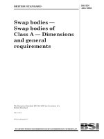
The combination of loads can be done by static
analysis (see Figure 4).
8.2 Acceptance criteria of the seismic
simulation
The seismic simulation waveforms shall produce a
test response spectrum which envelopes the
required response spectrum (calculated at the same
damping ratio) and have a peak acceleration equal
to or greater than the zero period acceleration.
8.3 Functional evaluation of the test results
Functional results are normally obtained only by
dynamic tests. These results may be extrapolated to
obtain qualification by combination of tests and
analysis. In particular:
a) the main contacts shall remain in position
during the seismic test;
b) chatter of relays shall not cause the
circuit-breaker to operate;
c) chatter of relays shall not provide wrong
information of the status of the circuit-breaker
(position, alarm signals).
NOTE Normally, chatter of relays during less than 5 ms is
considered to be acceptable.
d) resetting of monitoring equipment is
considered to be acceptable if the overall
performance of the circuit-breaker is not affected;
e) no significant change should occur in
functional checks recordings at the end of the test
sequence compared with the initial ones
(see 6.7.2.1).
© BSI 12-1999
EN 61166:1993
9 Documentation
9.1 Information for seismic qualification
The following information is required for either
analysis or testing of the circuit-breaker:
1) Severity (clause 5).
2) Details of mounting (6.2).
3) Number and relative position of testing axes.
9.2 Test report
The test report shall contain:
1) Circuit-breaker identification file including
mounting details.
2) Information for seismic qualification.
3) Test facility:
a) location;
b) test equipment description and calibration.
© BSI 12-1999
4) Test method and procedures.
5) Test data including functional data
(see 6.7.2.1 and 7.2).
6) Results and conclusions
7) Approved signature and date.
9.3 Analysis report
Analysis, which is included as a proof of
performance, should have a step-by-step
presentation.
7
EN 61166:1993
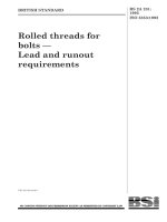
Amplitude
m/s2
Frequency
Damping
Damping
Damping
Damping
2%
5%
10 %
20 % and more
Hz
0,5
1,0
2,4
9,0
20,0
25,0
NOTE
4,3
8,5
14,0
14,0
7,5
5,0
2,9
5,2
8,7
8,7
7,0
5,0
2,1
4,3
6,4
7,3
6,4
5,0
1,8
3,2
5,2
6,1
5,2
5,0
According to IEC 68-3-3, the value of g is rounded up to the nearest unity, that is 10 m/s2.
Figure 1 — RRS for ground mounted equipment —
Qualification level: AF5: ZPA = 5 m/s2 (0,5 g)
8
© BSI 12-1999
EN 61166:1993
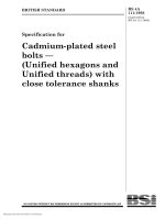
Amplitude
m/s2
Frequency
Hz
0,5
1,0
2,4
9,0
20,0
25,0
NOTE
2,6
5,1
8,5
8,5
4,5
3,0
Damping
Damping
Damping
Damping
2%
5%
10 %
20 % and more
1,8
3,2
5,1
5,1
4,1
3,0
1,4
2,3
3,8
4,2
3,8
3,0
0,8
1,6
2,9
3,6
3,1
3,0
According to IEC 68-3-3, the value of g is rounded up to the nearest unity, that is 10 m/s2.
Figure 2 — RRS for ground mounted equipment —
Qualification level: AF3: ZPA = 3 m/s2 (0,3 g)
© BSI 12-1999
9
EN 61166:1993
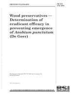
Amplitude
m/s2
Frequency
Hz
0,5
1,0
2,4
9,0
10,0
25,0
NOTE
1,7
3,4
5,6
5,6
5,0
2,0
Damping
Damping
Damping
Damping
2%
5%
10 %
20 % and more
1,2
2,2
3,4
3,4
2,8
2,0
0,8
1,7
2,6
2,8
2,6
2,0
0,6
1,2
2,0
2,4
2,4
2,0
According to IEC 68-3-3, the value of g is rounded up to the nearest unity, that is 10 m/s2.
Figure 3 — RRS for ground mounted equipment —
Qualification level AF2: ZPA = 2 m/s2 (0,2 g)
10
© BSI 12-1999
EN 61166:1993
Figure 4 — Example for combination of stresses
© BSI 12-1999
11
EN 61166:1993
Figure 5 — Graph for determining the damping ratio
12
© BSI 12-1999
EN 61166:1993
Annex A (normative)
Characterization of the equipment
A.1 Low level excitation
The method combines testing and analysis and
utilizes the application of excitation at points in the
circuit-breaker with low level excitation for
response determination.
A.1.1 Test method
With the circuit-breaker mounted to simulate the
recommended service mounting conditions, a
number of portable exciters are attached at the
points on the circuit-breaker which will best excite
its various modes of vibration.
The data obtained from the monitoring instruments
placed on the circuit-breaker can be used to analyze
the circuit-breaker’s seismic performance.
A.1.2 Analysis
The frequency response functions obtained from the
test can be used to determine the modal frequencies
and damping which may be used in a dynamic
analysis of the circuit-breaker. This method
provides a greater degree of certainty in analysis
since the analytical model can be refined to reflect
the measured natural frequencies and experimental
damping ratios can be used.
A.1.3 Qualification
This method can adequately qualify the
circuit-breaker in either of two ways, namely:
— the circuit-breaker can be excited to a level at
least equal to the expected response from a design
earthquake, using analysis to justify the
excitation;
— the test data on modal frequencies can be used
in a mathematical model to verify performance.
The first method is based upon the equivalence
between the effects due to the base excitation
(earthquake) and the concentrated force excitation.
The equivalence is obtained if the circuit-breaker
responses give the same relative displacements in
the two cases.
© BSI 12-1999
A.2 Free oscillation test
A.2.1 Natural frequency determination
To determine the natural frequency (first vibration
mode) of the circuit-breaker, the circuit-breaker,
fully furnished for service, shall be fixed to a rigid
foundation by the means provided for in its design.
A tensile force, of value not less than one-third of the
weight of the oscillating equipment, shall be applied
along the direction of maximum probable
amplitude, in the vicinity of the center of gravity of
the circuit-breaker. The oscillations of the
circuit-breaker shall be recorded when this force is
suddenly released.
A.2.2 Damping ratio determination
To determine the damping ratio of the
circuit-breaker, the same test may be used but, in
this case, the recording of the oscillations shall be
made with suitable sensitivity and accuracy to
determine the decrement of the oscillations as a
function of time. The equivalent damping ratio is
determined using the monogram in Figure 5, from
the sequence of peaks in the recorded wave, in that
range of the record in which the logarithmic
decrement appears most clear.
A.2.3 Special cases in the natural frequency
and damping ratio determination
When the circuit-breaker consists of different
elements, each one susceptible to vibration, the
tests in A.2.1 and A.2.2 shall be made by applying
tensile force around the centre of gravity of each of
the several masses subject to vibration and
simultaneously recording the oscillation of those
points corresponding to the greatest amplitude,
while attempting to detect all the modes of
oscillation in the arrangement. In such cases, it is
possible that the record of oscillations in one
element is influenced by the oscillations of some
other element with a nearby frequency, in which
case the determination shall be made as described
in the sketch of the top of Figure 5.
13
EN 61166:1993
Annex ZA (normative)
Other international publications quoted in this standard with the references of
the relevant European publications
When the international publication has been modified by CENELEC Common Modifications, indicated by
(mod), the relevant EN/HD applies
IEC publication
Date
Title
EN/HD
Date
50(441)
1984
International Electrotechnical Vocabulary
(IEV) — Part 441:Chapter 441: Switchgear,
controlgear and fuses
—
—
56, mod
1987
High-voltage alternating-current
circuit-breakers
HD 348 S4
1991
68-1
1988
Environmental testing
Part 1: General and guidance
HD 323.1 S2
1988
68-2-6
1982
Part 2: Tests — Test Fc and guidance:
Vibration (sinusoidal)
HD 323.2.6 S2a
1988
68-2-47
1982
Mounting of components, equipment and
other articles for dynamic tests including
shock (Ea), bump (Eb), vibration (Fc and Fd)
and steady-state acceleration (Ga) and guidance
EN 60068-2-47
1993
68-2-57
1989
Test Ff: Vibration — Time-history method
EN 60068-2-57
1993
68-3-3
1991
Part 3: Guidance — Seismic test methods for
equipments
EN 60068-3-3
1993
a
HD 323.2.6 S2 includes A1:1983 + A2:1985 to IEC 68-2-6.
14
© BSI 12-1999
BS EN 61166:1993
National annex NA (informative)
Committees responsible
The United Kingdom participation in the preparation of this European Standard was entrusted by the
Power Electrical Engineering Standards Policy Committee (PEL/-) to Technical Committee PEL/92, upon
which the following bodies were represented:
Asta Certification Services
Association of Manufacturers Allied to the Electrical and Electronic Industry
British Railways Board
Copper Development Association
ERA Technology Ltd.
Electricity Association
GAMBICA (BEAMA Ltd.)
Health and Safety Executive
PSA Projects Ltd.
Transmission and Distribution Association (BEAMA Ltd.)
The following bodies were also represented in the drafting of this standard through subcommittees and
panels:
Association of Consulting Engineers
Electrical Installation Equipment Manufacturers Association (BEAMA Ltd.)
Engineering Equipment and Materials Users’ Association
Institution of Incorporated Executive Engineers
National annex NB (informative)
Cross-references
Publication referred to
Corresponding British Standard
BS 2011 Environmental testing
IEC 68-1
Part 1.1:1989 General and guidance
IEC 68-2-6
Part 2.1 Fc:1983 Test Fc. Vibration (sinusoidal)
IEC 68-2-47
Section 4.1:1983 Specification for mounting of components, equipment and
other articles for dynamic tests
IEC 68-2-57
Part 2.1 Ff:1989 Test Ff. Vibration — time-history method
IEC 68-3-3
Section 4.3:1991 Guide to seismic test methods for equipments
© BSI 12-1999
BS EN
61166:1993
IEC 1166:1993
BSI — British Standards Institution
BSI is the independent national body responsible for preparing
British Standards. It presents the UK view on standards in Europe and at the
international level. It is incorporated by Royal Charter.
Revisions
British Standards are updated by amendment or revision. Users of
British Standards should make sure that they possess the latest amendments or
editions.
It is the constant aim of BSI to improve the quality of our products and services.
We would be grateful if anyone finding an inaccuracy or ambiguity while using
this British Standard would inform the Secretary of the technical committee
responsible, the identity of which can be found on the inside front cover.
Tel: 020 8996 9000. Fax: 020 8996 7400.
BSI offers members an individual updating service called PLUS which ensures
that subscribers automatically receive the latest editions of standards.
Buying standards
Orders for all BSI, international and foreign standards publications should be
addressed to Customer Services. Tel: 020 8996 9001. Fax: 020 8996 7001.
In response to orders for international standards, it is BSI policy to supply the
BSI implementation of those that have been published as British Standards,
unless otherwise requested.
Information on standards
BSI provides a wide range of information on national, European and
international standards through its Library and its Technical Help to Exporters
Service. Various BSI electronic information services are also available which give
details on all its products and services. Contact the Information Centre.
Tel: 020 8996 7111. Fax: 020 8996 7048.
Subscribing members of BSI are kept up to date with standards developments
and receive substantial discounts on the purchase price of standards. For details
of these and other benefits contact Membership Administration.
Tel: 020 8996 7002. Fax: 020 8996 7001.
Copyright
Copyright subsists in all BSI publications. BSI also holds the copyright, in the
UK, of the publications of the international standardization bodies. Except as
permitted under the Copyright, Designs and Patents Act 1988 no extract may be
reproduced, stored in a retrieval system or transmitted in any form or by any
means – electronic, photocopying, recording or otherwise – without prior written
permission from BSI.
This does not preclude the free use, in the course of implementing the standard,
of necessary details such as symbols, and size, type or grade designations. If these
details are to be used for any other purpose than implementation then the prior
written permission of BSI must be obtained.
BSI
389 Chiswick High Road
London
W4 4AL
If permission is granted, the terms may include royalty payments or a licensing
agreement. Details and advice can be obtained from the Copyright Manager.
Tel: 020 8996 7070.