Bsi bs en 61207 1 2010
Bạn đang xem bản rút gọn của tài liệu. Xem và tải ngay bản đầy đủ của tài liệu tại đây (1.25 MB, 44 trang )
BS EN 61207-1:2010
BSI Standards Publication
Expression of performance
of gas analyzers
Part 1: General
BRITISH STANDARD
BS EN 61207-1:2010
National foreword
This British Standard is the UK implementation of EN 61207-1:2010. It is
identical to IEC 61207-1:2010. It supersedes BS EN 61207-1:1994, which will
be withdrawn on 1 July 2013.
The UK participation in its preparation was entrusted by Technical Committee
GEL/65, Measurement and control, to Subcommittee GEL/65/2, Elements of
systems.
A list of organizations represented on this committee can be obtained on
request to its secretary.
This publication does not purport to include all the necessary provisions of a
contract. Users are responsible for its correct application.
© BSI 2011
ISBN 978 0 580 58438 1
ICS 71.040.40
Compliance with a British Standard cannot confer immunity from
legal obligations.
This British Standard was published under the authority of the
Standards Policy and Strategy Committee on 28 February 2011.
Amendments issued since publication
Amd. No.
Date
Text affected
BS EN 61207-1:2010
EUROPEAN STANDARD
EN 61207-1
NORME EUROPÉENNE
EUROPÄISCHE NORM
July 2010
ICS 19.080; 71.040.40
Supersedes EN 61207-1:1994
English version
Expression of performance of gas analyzers Part 1: General
(IEC 61207-1:2010)
Expression des performances
des analyseurs de gaz Partie 1: Généralités
(CEI 61207-1:2010)
Angabe zum Betriebsverhalten
von Gasanalysatoren Teil 1: Allgemeines
(IEC 61207-1:2010)
This European Standard was approved by CENELEC on 2010-07-01. CENELEC members are bound to comply
with the CEN/CENELEC Internal Regulations which stipulate the conditions for giving this European Standard
the status of a national standard without any alteration.
Up-to-date lists and bibliographical references concerning such national standards may be obtained on
application to the Central Secretariat or to any CENELEC member.
This European Standard exists in three official versions (English, French, German). A version in any other
language made by translation under the responsibility of a CENELEC member into its own language and notified
to the Central Secretariat has the same status as the official versions.
CENELEC members are the national electrotechnical committees of Austria, Belgium, Bulgaria, Croatia, Cyprus,
the Czech Republic, Denmark, Estonia, Finland, France, Germany, Greece, Hungary, Iceland, Ireland, Italy,
Latvia, Lithuania, Luxembourg, Malta, the Netherlands, Norway, Poland, Portugal, Romania, Slovakia, Slovenia,
Spain, Sweden, Switzerland and the United Kingdom.
CENELEC
European Committee for Electrotechnical Standardization
Comité Européen de Normalisation Electrotechnique
Europäisches Komitee für Elektrotechnische Normung
Management Centre: Avenue Marnix 17, B - 1000 Brussels
© 2010 CENELEC -
All rights of exploitation in any form and by any means reserved worldwide for CENELEC members.
Ref. No. EN 61207-1:2010 E
BS EN 61207-1:2010
EN 61207-1:2010
-2-
Foreword
The text of document 65B/741/FDIS, future edition 2 of IEC 61207-1, prepared by SC 65B, Devices &
process analysis, of IEC TC 65, Industrial-process measurement, control and automation, was submitted
to the IEC-CENELEC parallel vote and was approved by CENELEC as EN 61207-1 on 2010-07-01.
This European Standard supersedes EN 61207-1:1994.
The significant technical changes with respect to EN 61207-1:1994 are the following:
– All references (normative and informative) have been updated, deleted or added, as appropriate.
– All the terms and definitions relating to this International Standard have been updated.
– All references to “errors” have been replaced by “uncertainties” and appropriate updated definitions
applied.
– Where only one value is quoted for a performance specification, such as intrinsic uncertainty, linearity
uncertainty or repeatability throughout a measurement range, this has now been defined as the
maximum value, rather than an average or “representative” value. This was previously undefined.
– Where zero and 100 % span calibration gases are used, there is now a defined requirement that the
analyser must be able to respond within its standard performance specifications beyond its normal
measurement range, to allow for any under or over response of the instrument to be recorded.
– A new Annex A has been added giving recommended standard values of influence.
Attention is drawn to the possibility that some of the elements of this document may be the subject of
patent rights. CEN and CENELEC shall not be held responsible for identifying any or all such patent
rights.
The following dates were fixed:
– latest date by which the EN has to be implemented
at national level by publication of an identical
national standard or by endorsement
(dop)
2011-04-01
– latest date by which the national standards conflicting
with the EN have to be withdrawn
(dow)
2013-07-01
Annex ZA has been added by CENELEC.
__________
-3-
BS EN 61207-1:2010
EN 61207-1:2010
Endorsement notice
The text of the International Standard IEC 61207-1:2010 was approved by CENELEC as a European
Standard without any modification.
In the official version, for Bibliography, the following notes have to be added for the standards indicated:
IEC 61207-2
NOTE Harmonized as EN 61207-2.
IEC 61298 series
NOTE Harmonized in EN 61298 series (not modified).
IEC 61326 series
NOTE Harmonized in EN 61326 series (not modified).
ISO 6141
NOTE Harmonized as EN ISO 6141.
ISO 6142
NOTE Harmonized as EN ISO 6142.
ISO 6143
NOTE Harmonized as EN ISO 6143.
ISO 6144
NOTE Harmonized as EN ISO 6144.
ISO 9001
NOTE Harmonized as EN ISO 9001
ISO 16664
NOTE Harmonized as EN ISO 16664.
__________
BS EN 61207-1:2010
EN 61207-1:2010
-4-
Annex ZA
(normative)
Normative references to international publications
with their corresponding European publications
The following referenced documents are indispensable for the application of this document. For dated
references, only the edition cited applies. For undated references, the latest edition of the referenced
document (including any amendments) applies.
NOTE When an international publication has been modified by common modifications, indicated by (mod), the relevant EN/HD
applies.
Publication
Year
IEC 60068
Title
EN/HD
Year
Series Environmental testing
EN 60068
Series
IEC 60359
2001
Electrical and electronic measurement
equipment - Expression of performance
EN 60359
2002
IEC 60381-1
-
Analogue signals for process control
systems Part 1: Direct current signals
HD 452.1
-
IEC 60382
-
Analogue pneumatic signal for process
control systems
EN 60382
-
IEC 60654
Series Industrial-process measurement and control
equipment - Operating conditions -
EN 60654
Series
IEC 60654-1
-
EN 60654-1
-
IEC 60770
Series Transmitters for use in industrial-process
control systems
EN 60770
Series
IEC 60770-1
-
Transmitters for use in industrial-process
control systems Part 1: Methods for performance evaluation
EN 60770-1
-
IEC 61010-1
-
Safety requirements for electrical equipment EN 61010-1
for measurement, control and laboratory use Part 1: General requirements
-
IEC 61187
-
Electrical and electronic measuring
equipment - Documentation
EN 61187
-
ISO 31-0
-
Quantities and units Part 0: General principles
-
-
ISO 1000
-
SI units and recommendations for the use of their multiples and of certain other units
-
Industrial-process measurement and control
equipment - Operating conditions Part 1: Climatic conditions
BS EN 61207-1:2010
61207-1 © IEC:2010
CONTENTS
1
Scope and object..............................................................................................................6
2
Normative references .......................................................................................................7
3
Terms and definitions .......................................................................................................7
4
3.1 General ...................................................................................................................7
3.2 Basic terms and definitions......................................................................................8
3.3 General terms and definitions of devices and operations ....................................... 11
3.4 Terms and definitions on manners of expression ................................................... 15
3.5 Specific terms and definitions for gas analyzers .................................................... 18
Procedure for specification ............................................................................................. 20
4.1
4.2
4.3
4.4
5
Specification of values and ranges ........................................................................ 20
Operation, storage and transport conditions .......................................................... 21
Performance characteristics requiring statements of rated values.......................... 21
Uncertainty limits to be stated for each specified range ......................................... 22
4.4.1 General ..................................................................................................... 22
4.4.2 Limits of intrinsic uncertainty ..................................................................... 22
4.4.3 Variations .................................................................................................. 22
4.5 Other performance characteristics ......................................................................... 23
Procedure for compliance testing ................................................................................... 23
5.1
General ................................................................................................................. 23
5.1.1 Compliance tests ....................................................................................... 23
5.1.2 Test instruments ........................................................................................ 23
5.1.3 Test instrument uncertainties..................................................................... 23
5.1.4 Influence quantities ................................................................................... 24
5.1.5 Operational conditions ............................................................................... 24
5.2 Calibration gases .................................................................................................. 24
5.3 Adjustments made during tests.............................................................................. 24
5.4 Reference conditions during measurement of intrinsic uncertainty ......................... 24
5.5 Reference conditions during measurement of influence quantity............................ 24
5.6 Testing procedures................................................................................................ 25
5.6.1 General ..................................................................................................... 25
5.6.2 Intrinsic uncertainty ................................................................................... 25
5.6.3 Linearity uncertainty .................................................................................. 25
5.6.4 Repeatability ............................................................................................. 26
5.6.5 Output fluctuation ...................................................................................... 26
5.6.6 Drift ........................................................................................................... 27
5.6.7 Delay time, rise time and fall time .............................................................. 27
5.6.8 Warm-up time ............................................................................................ 28
5.6.9 Interference uncertainty ............................................................................. 28
5.6.10 Variations .................................................................................................. 29
Annex A (informative) Recommended standard values of influence – Quantities
affecting performance from IEC 60359 .................................................................................. 31
Annex B (informative) Performance characteristics calculable from drift tests ...................... 37
Bibliography.......................................................................................................................... 38
Figure 1 – Rise and fall times ............................................................................................... 20
BS EN 61207-1:2010
61207-1 © IEC:2010
–3–
Figure 2 – Output fluctuations ............................................................................................... 26
Table A.1 – Mains supply voltage ......................................................................................... 35
Table A.2 – Mains supply frequency ..................................................................................... 35
Table A.3 – Ripple of d.c. supply .......................................................................................... 36
Table B.1 – Data: applied concentration 1 000 units ............................................................. 37
BS EN 61207-1:2010
–6–
61207-1 © IEC:2010
EXPRESSION OF PERFORMANCE OF GAS ANALYZERS –
Part 1: General
1
Scope and object
This part of IEC 61207 is applicable to gas analyzers used for the determination of certain
constituents in gaseous mixtures.
This part of IEC 61207 specifies the terminology, definitions, requirements for statements by
manufacturers and tests that are common to all gas analyzers. Other international standards
in this series, for example IEC 61207-2, describe those aspects that are specific to certain
types (utilizing high-temperature electrochemical sensors).
This part IEC 61207 is in accordance with the general principles set out in IEC 60359 and
IEC 60770.
This standard is applicable to analyzers specified for permanent installation in any location
(indoors or outdoors) and to such analyzers utilizing either a sample handling system or an in
situ measurement technique.
This standard is applicable to the complete analyzer when supplied by one manufacturer as
an integral unit, comprised of all mechanical, electrical and electronic portions. It also applies
to sensor units alone and electronic units alone when supplied separately or by different
manufacturers.
For the purposes of this standard, any regulator for mains-supplied power or any non-mains
power supply, provided with the analyzer or specified by the manufacturer, is considered part
of the analyzer whether it is integral with the analyzer or housed separately.
Safety requirements are dealt with in IEC 61010-1.
If one or more components in the sample is flammable, and air or another gas mixture
containing oxygen or other oxidizing component is present, then the concentration range of
the reactive components are limited to levels which are not within flammability limits.
Standard range of analogue d.c. current and pneumatic signals used in process control
systems are dealt with in IEC 60381-1 and IEC 60382.
Specifications for values for the testing of influence quantities can be found in IEC 60654.
Requirements for documentation to be supplied with instruments are dealt with in IEC 61187.
Requirements for general principles concerning quantities, units and symbols are dealt with in
ISO 1000. See also ISO 31-0.
This part of IEC 61207 does not apply to:
–
accessories such as recorders, analogue-to-digital converters or data acquisition systems
used in conjunction with the analyzer, except that when two or more such analyzers are
combined and sold as a subsystem and a single electronic unit is supplied to provide
continuous measurement of several properties, that read-out unit is considered to be part
of the analyzer. Similarly, e.m.f-to-current or e.m.f-to-pressure converters which are an
integral part of the analyzer are included.
BS EN 61207-1:2010
61207-1 © IEC:2010
–7–
The object of this part of IEC 61207 is:
–
to specify the general aspects in the terminology and definitions related to the
performance of gas analyzers used for the continuous measurement of gas composition;
–
to unify methods used in making and verifying statements on the functional performance of
such analyzers;
–
to specify which tests should be performed in order to determine the functional
performance and how such tests should be carried out;
–
to provide basic documents to support the application of standards of quality assurance
within ISO 9001.
2
Normative references
The following referenced documents are indispensable for the application of this document.
For dated references, only the edition cited applies. For undated references, the latest edition
of the referenced document (including any amendments) applies.
IEC 60068 (all parts), Environmental testing
IEC 60359:2001,
performance
Electrical
and
electronic
measurement
equipment
–
Expression
of
IEC 60381-1, Analogue signals for process control systems – Part 1: Direct current signals
IEC 60382, Analogue pneumatic signal for process control systems
IEC 60654 (all parts), Industrial-process measurement and control equipment – Operating
conditions
IEC 60654-1, Industrial-process measurement and control equipment – Operating conditions –
Part 1: Climatic conditions
IEC 60770 (all parts), Transmitters for use in industrial-process control systems
IEC 60770-1, Transmitters for use in industrial-process control systems – Part 1: Methods for
performance evaluation
IEC 61010-1, Safety requirements for electrical equipment for measurement, control and
laboratory use – Part 1: General requirements
IEC 61187, Electrical and electronic measurement equipment – Documentation
ISO 31-0, Quantities and units – General principles
ISO 1000, SI units and recommendations for the use of their multiples and of certain other
units
3
3.1
Terms and definitions
General
For the purposes of this document, the following terms and definitions apply. The definitions
in 3.2 (excepting 3.2.17), 3.3 and 3.4 are taken from IEC 60359.
BS EN 61207-1:2010
–8–
3.2
61207-1 © IEC:2010
Basic terms and definitions
3.2.1
measurand
quantity subjected to measurement, evaluated in the state assumed by the measured system
during the measurement itself
NOTE 1 The value assumed by a quantity subjected to measurement when it is not interacting with the measuring
instrument may be called unperturbed value of the quantity.
NOTE 2 The unperturbed value and its associated uncertainty can only be computed through a model of the
measured system and of the measurement interaction with the knowledge of the appropriate metrological
characteristics of the instrument that may be called instrumental load.
3.2.2
(result of a) measurement
set of values attributed to a measurand, including a value, the corresponding uncertainty and
the unit of measurement
[IEC 60050-311, 311-01-01, modified]
NOTE 1 The mid-value of the interval is called the value (see 3.2.3) of the measurand and its half-width the
uncertainty (see 3.2.4).
NOTE 2 The measurement is related to the indication (see 3.2.5) given by the instrument and to the values of
correction obtained by calibration.
NOTE 3 The interval can be considered as representing the measurand provided that it is compatible with all
other measurements of the same measurand.
NOTE 4 The width of the interval, and hence the uncertainty, can only be given with a stated level of confidence
(see 3.2.4, NOTE 1).
3.2.3
(measure-) value
mid element of the set assigned to represent the measurand
NOTE The measure-value is no more representative of the measurand than any other element of the set. It is
singled out merely for the convenience of expressing the set in the format V ± U, where V is the mid element and U
the half-width of the set, rather than by its extremes. The qualifier "measure-" is used when deemed necessary to
avoid confusion with the reading-value or the indicated value.
3.2.4
uncertainty (of measurement)
parameter, associated with the result of a measurement, that characterizes the dispersion of
the values that could reasonably be attributed to the measurand
NOTE 1 The parameter can be, for example, a standard deviation (or a given multiple of it), or a half-width of an
interval having a stated level of confidence.
NOTE 2 Uncertainty of measurement comprises, in general, many components. Some of these components can
be evaluated from the statistical distribution of the results of a series of measurements and can be characterized
by experimental standard deviations. The other components, which can also be characterized by standard
deviations, are evaluated from the assumed probability distributions based on experience or other information.
[IEC 60050-311, 311-01-02, ISO/IEC Guide 99, 2.26 modified]
NOTE 3 It is understood that the result of the measurement is the best estimate of the value of the measurand,
and that all components of uncertainty, including those arising from systematic effects, such as components
associated with corrections and reference standards, contribute to the dispersion.
NOTE 4 The definition and notes 1 and 2 are from GUM, Clause B.2.18. The option used in this standard is to
express the uncertainty as the half-width of an interval with the GUM procedures with a coverage factor of 2. This
choice corresponds to the practice now adopted by many national standards laboratories. With the normal
distribution a coverage factor of 2 corresponds to a level of confidence of 95 %. Otherwise statistical elaborations
are necessary to establish the correspondence between the coverage factor and the level of confidence. As the
data for such elaborations are not always available, it is deemed preferable to state the coverage factor. This
interval can be "reasonably" assigned to describe the measurand, in the sense of the GUM definition, as in most
BS EN 61207-1:2010
61207-1 © IEC:2010
–9–
usual cases it ensures compatibility with all other results of measurements of the same measurand assigned in the
same way at a sufficiently high confidence level.
NOTE 5 Following CIPM document INC-1 and ISO/IEC Guide 98-3, the components of uncertainty that are
evaluated by statistical methods are referred to as components of category A, and those evaluated with the help of
other methods as components of category B.
3.2.5
indication or reading-value
output signal of the instrument
[IEC 60050-311, 311-01-01, modified]
NOTE 1
The indicated value can be derived from the indication by means of the calibration curve.
NOTE 2
For a material measure, the indication is its nominal or stated value.
NOTE 3
The indication depends on the output format of the instrument:
–
for analogue outputs it is a number tied to the appropriate unit of the display;
–
for digital outputs it is the displayed digitized number;
–
for code outputs it is the identification of the code pattern.
NOTE 4 For analogue outputs meant to be read by a human observer (as in the index-on-scale instruments) the
unit of output is the unit of scale numbering; for analogue outputs meant to be read by another instrument (as in
calibrated transducers) the unit of output is the unit of measurement of the quantity supporting the output signal.
3.2.6
calibration
set of operations which establishes the relationship which exists, under specified conditions,
between the indication and the result of a measurement
[IEC 60050-311, 311-01-09]
NOTE 1 The relationship between the indications and the results of measurement can be expressed, in principle,
by a calibration diagram.
NOTE 2 The calibration must be performed under well-defined operating conditions for the instrument. The
calibration diagram representing its result is not valid if the instrument is operated under conditions outside the
range used for the calibration.
NOTE 3 Quite often,e specially for instruments whose metrological characteristics are sufficiently known from
past experience, it is convenient to predefine a simplified calibration diagram and perform only a verification of
calibration (see 3.3.12) to check whether the response of the instrument stays within its limits. The simplified
diagram is, of course, wider than the diagram that would be defined by the full calibration of the instrument, and
the uncertainty assigned to the results of measurements is consequently larger.
3.2.7
calibration diagram
portion of the co-ordinate plane, defined by the axis of indication and the axis of results of
measurement, which represents the response of the instrument to differing values of the
measurand
[IEC 60050-311, 311-01-10]
3.2.8
calibration curve
curve which gives the relationship between the indication and the value of the measurand
NOTE 1 When the calibration curve is a straight line passing through zero, it is convenient to refer to the slope
which is known as the instrument constant.
[IEC 60050-311, 311-01-11]
NOTE 2 The calibration curve is the curve bisecting the width of the calibration diagram parallel to the axis of
results of measurement, thus joining the points representing the values of the measurand.
BS EN 61207-1:2010
– 10 –
61207-1 © IEC:2010
3.2.9
indicated value
value given by an indicating instrument on the basis of its calibration curve
[IEC 60050-311, 311-01-08]
NOTE The indicated value is the measure-value of the measurand when the instrument is used in a direct
measurement (see 3.3.7) under all the operating conditions for which the calibration diagram is valid.
3.2.10
(measurement) compatibility
property satisfied by all the results of measurement of the same measurand, characterized by
an adequate overlap of their intervals
[IEC 60050-311, 311-01-14]
NOTE 1 The compatibility of any result of a measurement with all the other ones that represent the same
measurand can be asserted only at some level of confidence, as it depends on statistical inference, a level that
should be indicated, at least by implicit convention or through a coverage factor.
NOTE 2 The compatibility of the results of measurements obtained with different instruments and methods is
ensured by the traceability (see 3.2.16) to a common primary standard (see 3.3.6) of the standards used for the
calibration of the several instruments (and of course by the correctness of the calibration and operation
procedures).
NOTE 3 When two results of a measurement are not compatible it must be decided by independent means
whether one or both results are wrong (perhaps because the uncertainty is too narrow), or whether the measurand
is not the same.
NOTE 4 Measurements carried out with wider uncertainty yield results which are compatible on a wider range,
because they discriminate less among different measurands allowing to classify them with simpler models; with
narrower uncertainties the compatibility calls for more detailed models of the measured systems.
3.2.11
intrinsic uncertainty of the measurand
minimum uncertainty that can be assigned in the description of a measured quantity
NOTE 1 No quantity can be measured with narrower and narrower uncertainty, in as much as any given quantity
is defined or identified at a given level of detail. If one tries to measure a given quantity with uncertainty lower than
its own intrinsic uncertainty one is compelled to redefine it with higher detail, so that one is actually measuring
another quantity. See also GUM D.1.1.
NOTE 2 The result of a measurement carried out with the intrinsic uncertainty of the measurand may be called the
best measurement of the quantity in question.
3.2.12
(absolute) instrumental uncertainty
uncertainty of the result of a direct measurement of a measurand having negligible intrinsic
uncertainty
NOTE 1 Unless explicitly stated otherwise, the instrumental uncertainty is expressed as an interval with coverage
factor 2.
NOTE 2 In single-reading direct measurements of measurands having intrinsic uncertainty small with respect to
the instrumental uncertainty, the uncertainty of the measurement coincides, by definition, with the instrumental
uncertainty. Otherwise the instrumental uncertainty is to be treated as a component of category B in evaluating the
uncertainty of the measurement on the basis of the model connecting the several direct measurements involved.
NOTE 3 The instrumental uncertainty automatically includes, by definition, the effects due to the quantization of
the reading-values (minimum evaluable fraction of the scale interval in analogic outputs, unit of the last stable digit
in digital outputs).
NOTE 4 For material measures the instrumental uncertainty is the uncertainty that should be associated to the
value of the quantity reproduced by the material measure in order to ensure the compatibility of the results of its
measurements.
NOTE 5 When possible and convenient the uncertainty may be expressed in the relative form (see 3.4.3) or in the
fiducial form (see 3.4.4). The relative uncertainty is the ratio U/V of the absolute uncertainty U to the measure
BS EN 61207-1:2010
61207-1 © IEC:2010
– 11 –
value V, and the fiducial uncertainty the ratio U/V f of the absolute uncertainty U to a conventionally chosen value
Vf.
3.2.13
conventional value measure
value of a standard used in a calibration operation and known with uncertainty negligible with
respect to the uncertainty of the instrument to be calibrated
NOTE This definition is adapted to the object of this standard from the definition of "conventional true value (of a
quantity)": value attributed to a particular quantity and accepted, sometimes by convention, as having an
uncertainty appropriate for a given purpose (see IEC 60050-311, 311-01-06, ISO/IEC Guide 99, 2.13 modified).
3.2.14
influence quantity
quantity which is not the subject of the measurement and whose change affects the
relationship between the indication and the result of the measurement
NOTE 1 Influence quantities can originate from the measured system, the measuring equipment or the
environment.
NOTE 2 As the calibration diagram depends on the influence quantities, in order to assign the result of a
measurement it is necessary to know whether the relevant influence quantities lie within the specified range.
[IEC 60050-311, 311-06-01]
NOTE 3 An influence quantity is said to lie within a range C’ to C" when the results of its measurement satisfy the
relationship: C' ≤ V – U < V + U ≤ C".
3.2.15
steady-state conditions
operating conditions of a measuring device in which the variation of the measurand with the
time is such that the relation between the input and output signals of the instruments does not
suffer a significant change with respect to the relation obtaining when the measurand is
constant in time
3.2.16
traceability
property of the result of a measurement or of the value of a standard such that it can be
related to stated references, usually national or international standards, through an unbroken
chain of comparisons all having stated uncertainties
[IEC 60050-311, 311-01-15, ISO/IEC Guide 99, 2.41 modified]
NOTE 1
The concept is often expressed by the adjective traceable.
NOTE 2
The unbroken chain of comparisons is called a traceability chain.
NOTE 3 The traceability implies that a metrological organization be established with a hierarchy of standards
(instruments and material measures) of increasing intrinsic uncertainty. The chain of comparisons from the primary
standard to the calibrated device adds indeed new uncertainty at each step.
NOTE 4
Traceability is ensured only within a given uncertainty that should be specified.
3.2.17
mean
summation of the individual values divided by the total number of values for a set of values
3.3
General terms and definitions of devices and operations
3.3.1
(measuring) instrument
device intended to be used to make measurements, alone or in conjunction with
supplementary devices
[IEC 60050-311, 311-03-01, ISO/IEC Guide 99, 3.1 modified]
BS EN 61207-1:2010
– 12 –
NOTE
61207-1 © IEC:2010
The term "(measuring) instruments" includes both the indicating instruments and the material measures.
3.3.2
indicating (measuring) instrument
measuring instrument which displays an indication
NOTE 1
The display can be analogue (continuous or discontinuous), digital or coded [IEV].
NOTE 2
Values of more than one quantity can be displayed simultaneously [IEV].
NOTE 3
A displaying measuring instrument can also provide a record [IEV].
NOTE 4 The display can consist of an output signal not directly readable by a human observer, but able to be
interpreted by suitable devices [IEV].
[IEC 60050-311, 311-03-02, ISO/IEC Guide 99, 3.3 modified]
NOTE 5 An indicating instrument may consist of a chain of transducers with the possible addition of other process
devices, or it may consist of one transducer.
NOTE 6 The interaction between the indicating instrument, the measured system and the environment generates
a signal in the first stage of the instrument (called sensor). This signal is elaborated inside the instrument into an
output signal which carries the information on the measurand. The description of the output signal in a suitable
output format is the indication supplied by the instrument.
NOTE 7 A chain of instruments is treated as a single indicating instrument when a single calibration diagram is
available that connects the measurand to the output of the last element of the chain. In this case the influence
quantities must be defined for the whole chain.
3.3.3
material measure
device intended to reproduce or supply, in a permanent manner during its use, one or more
known values of a given quantity
NOTE 1
The quantity concerned may be called the supplied quantity [IEV].
[IEC 60050-311, 311-03-03, ISO/IEC Guide 99, 3.6 modified]
NOTE 2 The definition covers also the devices, such as signal generators and standard voltage or current
generators, often referred to as supply instruments.
NOTE 3 The identification of the value and uncertainty of the supplied quantity is given by a number tied to a unit
of measurement or a code term, called nominal value or marked value of the material measure.
3.3.4
electrical measuring instrument
measuring instrument intended to measure an electrical or non-electrical quantity using
electrical or electronic means
[IEC 60050-311, 311-03-04]
3.3.5
transducer
technical device which performs a given elaboration on an input signal, transforming it into an
output signal
NOTE All indicating instruments contain transducers and they may consist of one transducer. When the signals
are elaborated by a chain of transducers, the input and output signals of each transducer are not always directly
and univocally accessible.
3.3.6
primary standard
standard that is designated or widely acknowledged as having the highest metrological
qualities and whose value is accepted without reference to other standards of the same
quantity
NOTE 1
The concept of a primary standard is equally valid for base quantities and derived quantities.
BS EN 61207-1:2010
61207-1 © IEC:2010
– 13 –
NOTE 2 A primary standard is never used directly for measurement other than for comparison with other primary
standards or reference standards.
[IEC 60050-311, 311-04-02, ISO/IEC Guide 99, 5.4 modified]
3.3.7
direct (method of) measurement
method of measurement in which the value of a measurand is obtained directly, without the
necessity for supplementary calculations based on a functional relationship between the
measurand and other quantities actually measured
NOTE 1 The value of the measurand is considered to be obtained directly even when the scale of a measuring
instrument has values which are linked to corresponding values of the measurand by means of a table or a graph
[IEV].
NOTE 2 The method of measurement remains direct even if it is necessary to make supplementary measurements
to determine the values of influence quantities in order to make corrections [IEV].
[IEC 60050-311, 311-02-01]
NOTE 3 The definitions of the metrological characteristics of the instruments refer implicitly to their use in direct
measurements.
3.3.8
indirect (method of) measurement
method of measurement in which the value of a quantity is obtained from measurements
made by direct methods of measurement of other quantities linked to the measurand by a
known relationship
[IEC 60050-311, 311-02-02]
NOTE 1 In order to apply an indirect method of measurement a model is needed which is able to supply the
relationship, and which is fully explicit, between the measurand and the parameters that are measured by direct
measurement.
NOTE 2 The computations must be carried out on both values and uncertainties, and therefore require accepted
rules for the propagation of the uncertainty as provided by GUM.
3.3.9
(method of) measurement by repeated observations
method of measurement by which the result of the measurement is assigned on the basis of a
statistical analysis on the distribution of the data obtained by several observations repeated
under nominally equal conditions
NOTE 1 One should resort to a statistical analysis when the instrumental uncertainty is too small to ensure the
measurement compatibility. This may happen in two quite different sets of circumstances:
a)
when the measurand is a quantity subjected to intrinsic statistical fluctuations (e.g. in measurements involving
nuclear decay). In this case the actual measurand is the statistical distribution of the states of the measured
quantity, to be described by its statistical parameters (mean and standard deviation). The statistical analysis is
carried out on a population of results of measurement, each with its own value and uncertainty, as each
observation correctly describes one particular state of the measured quantity. The situation may be considered
a particular case of indirect measurement.
b)
when the noise associated with the transmission of signals affects the reading-value more than in the
operating conditions used for the calibration, contributing to the uncertainty of the measurement to an extent
comparable with the instrumental uncertainty or higher (e.g. in the field use of surveyor instruments). In this
case, the statistical analysis is carried out on a population of reading-values with the purpose of separating the
information on the measurand from the noise. The situation may be considered as a new calibration of the
instrument for a set of operating conditions outside their rated range.
NOTE 2 One cannot presume to obtain by means of repeated observation an uncertainty lower than the
instrumental uncertainty assigned by the calibration or the class of precision of the instrument. Indeed, if the
results of the repeated measurements are compatible with each other within the instrumental uncertainty, the latter
is the valid datum for the uncertainty of the measurement and several observations do not bring more information
than one. In the other hand, if they are not compatible within the instrumental uncertainty, the final result of the
measurement should be expressed with a larger uncertainty in order to make all results compatible as they should
be by definition.
BS EN 61207-1:2010
– 14 –
61207-1 © IEC:2010
NOTE 3 For instruments that exhibit non-negligible hysteresis a straightforward statistical analysis of repeated
observations is misleading. Appropriate test procedures for such instruments should be expounded in their
particular standards.
3.3.10
intrinsic (instrumental) uncertainty
uncertainty of a measuring instrument when used under reference conditions
[IEC 60050-311, 311-03-09, modified]
3.3.11
operating instrumental uncertainty
instrumental uncertainty under the rated operating conditions
NOTE The operating instrumental uncertainty, like the intrinsic one, is not evaluated by the user of the
instrument, but is stated by its manufacturer or calibrator. The statement may be expressed by means of an
algebraic relation involving the intrinsic instrumental uncertainty and the values of one or several influence
quantities, but such a relation is just a convenient means of expressing a set of operating instrumental
uncertainties under different operating conditions, not a functional relation to be used for evaluating the
propagation of uncertainty inside the instrument.
3.3.12
verification (of calibration)
set of operations which is used to check whether the indications, under specified conditions,
correspond with a given set of known measurands within the limits of a predetermined
calibration diagram
NOTE 1 The known uncertainty of the measurand used for verification will generally be negligible with respect to
the uncertainty assigned to the instrument in the calibration diagram.
[IEC 60050-311, 311-01-13]
NOTE 2 The verification of calibration of a material measure consists in checking whether the result of a
measurement of the supplied quantity is compatible with the interval given by the calibration diagram.
3.3.13
adjustment (of a measuring instrument)
set of operations carried out on an measuring instrument in order that it provides given
indications corresponding to given values of the measurand
NOTE When the instrument is made to give a null indication corresponding to a null value of the measurand, the
set of operations is called zero adjustment.
[IEC 60050-311, 311-03-16]
3.3.14
user adjustment (of a measuring instrument)
adjustment, employing only the means at the disposal of the user, specified by the
manufacturer
[IEC 60050-311, 311-03-17]
3.3.15
deviation (for the verification of calibration)
difference between the indication of an instrument undergoing verification of calibration and
the indication of the reference measuring instrument, under equivalent operating conditions
[IEC 60050-311, 311-01-21]
NOTE 1 The comparison of the indications may be carried out by simultaneous measurement or by substitution.
In principle, the comparison ought to be carried out on the same measurand in the same measuring conditions, but
this is impossible because the measurand can never be rigorously the same. Only the metrological expertise of the
operator can warranty that the difference in the measurement conditions of the two instruments is negligible for
comparison purposes.
BS EN 61207-1:2010
61207-1 © IEC:2010
NOTE 2
value.
– 15 –
If one of the instruments is a material measure, its nominal value is taken as the assigned measure -
NOTE 3 The term is used only in operations of verification of calibration where the uncertainty of the reference
instrument is negligible by definition.
3.4
Terms and definitions on manners of expression
3.4.1
metrological characteristics
data concerning the relations between the readings of a measuring instrument and the
measurements of the quantities interacting with it
3.4.2
range
domain of values of a quantity included between a lower and an upper limit
NOTE 1 The term "range" is usually used with a modifier. It may apply to a performance characteristic, to an
influence quantity, etc.
NOTE 2
When one of the limits of a range is zero or infinity, the other finite limit is called a threshold.
NOTE 3 No uncertainty is associated with the values of range limits or thresholds as they are not themselves
results of measurements but a priori statements about conditions to be met by results of measurements. If the
result of a measurement have to lie within a rated range, it is understood that the whole interval V ± U representing
it must lie within the values of the range limits or beyond the threshold value, unless otherwise specified by
relevant standards or by explicit agreements.
NOTE 4 A range may be expressed by stating the values of its lower and upper limits, or by stating its mid value
and its half-width.
3.4.3
relative form of expression
expression of a metrological characteristic, or of other data, by means of its ratio to the
measure value of the quantity under consideration
NOTE 1 Expression in relative form is possible when the quantity under consideration allows the ratio relationship
and its value is not zero.
NOTE 2 Uncertainties and limits of uncertainty are expressed in relative form by dividing their absolute value by
the value of the measurand, ranges of influence quantities by dividing the halved range by the mid value of the
domain, etc.
3.4.4
fiducial form of expression
expression of a metrological characteristic, or of other data, by means of its ratio to a
conventionally chosen value of the quantity under consideration
NOTE 1 Expression in fiducial form is possible when the quantity under consideration allows the ratio
relationship.
NOTE 2
The value to which reference is made in order to define the uncertainity is called fiducial value.
3.4.5
variation (due to an influence quantity)
difference between the indicated values for the same value of the measurand of an indicating
instrument, or the values of a material measure, when an influence quantity assumes,
successively, two different values
[IEC 60050-311, 311-07-03]
NOTE 1 The uncertainty associated with the different measure values of the influence quantity for which the
variation is evaluated should not be wider than the width of the reference range for the same influence quantity.
The other performance characteristics and the other influence quantities should stay within the ranges specified for
the reference conditions.
NOTE 2
The variation is a meaningful parameter when it is greater than the intrinsic instrumental uncertainty.
BS EN 61207-1:2010
– 16 –
61207-1 © IEC:2010
3.4.6
limit of uncertainty
limiting value of the instrumental uncertainty for equipment operating under specified
conditions
NOTE 1 A limit of uncertainty may be assigned by the manufacturer of the instrument, who states that under the
specified conditions the instrumental uncertainty is never higher than this limit, or may be defined by standards,
that prescribe that under specified conditions the instrumental uncertainty should not be larger than this limit for
the instrument to belong to a given accuracy class.
NOTE 2
A limit of uncertainty may be expressed in absolute terms or in the relative or fiducial forms.
3.4.7
accuracy class
class of measuring instruments, all of which are intended to comply with a set of
specifications regarding uncertainty
[IEC 60050-311, 311-06-09]
NOTE 1 An accuracy class always specifies a limit of uncertainty (for a given range of influence quantities),
whatever other metrological characteristics it specifies.
NOTE 2
An instrument may be assigned to different accuracy classes for different rated operating conditions.
NOTE 3 Unless otherwise specified, the limit of uncertainty defining an accuracy class is meant as an interval
with coverage factor 2.
3.4.8
rated value
quantity value assigned by a manufacturer for a specified operating condition of the
equipment or instrument
NOTE A rated value V assigned with an uncertainty U is actually a range V ± U and should be handled as such
(see 3.4.2, Note 4).
3.4.9
(specified) measuring range
range defined by two values of the measurand, or quantity to be supplied, within which the
limits of uncertainty of the measuring instrument are specified
NOTE 1
An instrument can have several measuring ranges.
[IEC 60050-311, 311-03-12, modified]
NOTE 2 The upper and lower limits of the specified measuring range are sometimes called the maximum capacity
and minimum capacity respectively.
3.4.10
reference conditions
appropriate set of specified values and/or ranges of values of influence quantities under which
the smallest permissible uncertainties of a measuring instrument are specified
[IEC 60050-311, 311-06-02, modified]
NOTE The ranges specified for the reference conditions, called reference ranges, are not wider, and are usually
narrower, than the ranges specified for the rated operating conditions.
3.4.11
reference value
specified value of one of a set of reference conditions
[IEC 60050-311, 311-07-01, modified]
BS EN 61207-1:2010
61207-1 © IEC:2010
– 17 –
3.4.12
reference range
specified range of values of one of a set of reference conditions
[IEC 60050-311, 311-07-02, modified]
3.4.13
rated operating conditions
set of conditions that must be fulfilled during the measurement in order that a calibration
diagram may be valid
NOTE Beside the specified measuring range and rated operating ranges for the influence quantities, the
conditions may include specified ranges for other performance characteristics and other indications that cannot be
expressed as ranges of quantities.
3.4.14
nominal range of use or rated operating range (for influence quantities)
specified range of values which an influence quantity can assume without causing a variation
exceeding specified limits
[IEC 60050-311, 311-07-05]
NOTE
The rated operating range of each influence quantity is a part of the rated operating conditions.
3.4.15
limiting conditions
extreme conditions which an operating measuring instrument can withstand without damage
and without degradation of its metrological characteristics when it is subsequently operated
under its rated operating conditions
3.4.16
limiting values for operation
extreme values which an influence quantity can assume during operation without damaging
the measuring instrument so that it no longer meets its performance requirements when it is
subsequently operated under reference conditions
NOTE
The limiting values can depend on the duration of their application.
[IEC 60050-311, 311-07-06]
3.4.17
storage and transport conditions
extreme conditions which a non-operating measuring instrument can withstand without
damage and without degradation of its metrological characteristics when it is subsequently
operated under its rated operating conditions
3.4.18
limiting values for storage
extreme values which an influence quantity can assume during storage without damaging the
measuring instrument so that it no longer meets its performance requirements when it is
subsequently operated under reference conditions
NOTE
The limiting values can depend on the duration of their application.
[IEC 60050-311, 311-07-07]
3.4.19
limiting values for transport
extreme values which an influence quantity can assume during transport without damaging
the instrument so that it no longer meets its performance requirements when it is
subsequently operated under reference conditions
BS EN 61207-1:2010
– 18 –
NOTE
61207-1 © IEC:2010
The limiting values can depend on the duration of their application.
[IEC 60050-311, 311-07-08]
3.5
Specific terms and definitions for gas analyzers
3.5.1
gas analyzer
analytical instrument that provides an output signal which is a monotonic function of the
concentration, partial pressure or condensation temperature of one or more components of a
gas mixture
3.5.2
stable test gas mixture
mixture of gases (and/or vapour) where the component to be measured is known and does
not react with, and is not adsorbed on to the containment system (such as a gas cylinder).
The concentrations of gases and their uncertainty ranges shall be known for the components
of the gas mixture, and commensurate with the criteria to be evaluated.
NOTE
For preparation of these mixtures, refer to documents in the Bibliography.
3.5.3
calibration gas
stable test gas mixture of known concentration used for periodic calibration of the analyzer
and for various performance tests
NOTE 1 For the purpose of this part the parameter to be measured should be expressed in SI units, as in
ISO 31-0.
NOTE 2 For example, the partial pressure of a component in Pascals. Alternatively, the ratio of partial pressure to
total pressure, this being the same as the volume ratio or the mole ratio for ideal gases. The mass of the
component per unit volume has also been used but the component and physical conditions should be stated.
NOTE 3 For the purpose of this part the value of the parameter represents the conventional value, against which
the indicated value is compared.
NOTE 4 If the calibration gas mixture is unstable, some components of the mixture can be replaced by substitutes
which increase stability and give a known change in analyzer sensitivity, subject to agreement between the
manufacturer and the user.
3.5.4
zero gas
calibration gas mixture used to calibrate the lower end of a specified calibration range. This
should be of a value which is either at or close to the specified lowest value in the given
calibration range when used with a defined analytical procedure.
3.5.5
span gas
calibration gas mixture used to establish the span point (maximum or near maximum value of
range) of a calibration curve when used with a given analytical procedure within a defined
calibration range.
3.5.6
performance
degree to which the intended functions of an instrument are accomplished
3.5.7
performance characteristic
one of the quantities (described by values, tolerances, range) assigned to an equipment in
order to define its performance
NOTE 1 Depending on its application, one and the same quantity may be referred to in this part as a
"performance characteristic", as a "measured or supplied quantity", and also may act as an "influence quantity".
BS EN 61207-1:2010
61207-1 © IEC:2010
– 19 –
NOTE 2 In addition, the term "performance characteristic" includes quotients of quantities, such as voltage per
unit of length.
3.5.8
linearity uncertainty
maximum deviation between actual analyzer readings and the readings predicted by a linear
function of the measured quantity which includes the indicated values at the upper and lower
limits of the effective range
3.5.9
repeatability
spread of the results from measurements taken on successive samples at short intervals of
time with identical test material, carried out by the same method, with the same measuring
instruments, by the same observer, in the same laboratory, in unchanged environmental
conditions
NOTE 1 A time interval equal to about 10 times the 90 % response time of the analyzer may be considered a
short interval.
NOTE 2 When practical, the approach to the measured value should be from both upscale and downscale
directions.
3.5.10
drift
change of the indications of an analyzer, for a given level of concentration over a stated
period of time, under reference conditions which remain constant and without any adjustments
being made to the analyzer by external means
NOTE
The rate of change of uncertainty with time is derived by linear regression.
3.5.11
output fluctuation
peak-to-peak deviations of the output with constant input and constant influence quantities
3.5.12
minimum detectable change
change in value of the property to be measured equivalent to twice the output fluctuation
measured over a 5 min period
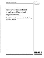
3.5.13
delay time
T 10
time interval from the instant a step change occurs in the value of the property to be
measured to the instant when the change in the indicated value passes (and remains beyond)
10 % of its steady-state amplitude difference
NOTE In cases where the rising delay time and falling delay time differ, the different delay times should be
specified.
3.5.14
90 % response time
T 90
time interval from the instant a step change occurs in the value of the property to be
measured to the instant when the change in the indicated value passes (and remains beyond)
90 % of its steady-state amplitude difference, that is, T 90 = T 10 + T r (or T f )
NOTE In cases where the rising and falling response times differ, the different response times should be
specified.
BS EN 61207-1:2010
61207-1 © IEC:2010
– 20 –
3.5.15
rise (fall) time
Tr, Tf
difference between the 90 % response time and delay time (see Figure 1)
T90
T10
Tf
100 %
90 %
Step change
Step change
10 %
10 %
90 %
100 %
T10
Tr
T90
IEC 1097/10
Figure 1 – Rise and fall times
3.5.16
warm-up time
time interval after switching on the power, under reference conditions, necessary for a unit or
analyzer to comply with and remain within specific limits of uncertainity
3.5.17
interference uncertainty
special category of influence quantity; it is the uncertainty caused by interfering substances
being present in the sample
3.5.18
limits of uncertainty
maximum values of uncertainty assigned by the manufacturer to a measured quantity of an
apparatus operating under specified conditions
4
4.1
Procedure for specification
Specification of values and ranges
The manufacturer shall state rated values or specified measuring ranges for all parameters
which are considered to be performance characteristics applicable to the particular
equipment. The statements on values and ranges shall be accompanied by the appropriate
statements on uncertainty. The manufacturer shall state a reference range and/or a rated
operating range for each influence quantity which is taken into account. The rated operating
range shall include the whole of the reference range.
These statements shall cover the parameters listed below, which will be described in the
following subclauses:
BS EN 61207-1:2010
61207-1 © IEC:2010
– 21 –
–
operation and storage requirements;
–
specification of ranges of measurement and output signals;
–
limits of uncertainties;
–
recommended reference values and rated ranges of influence quantities.
4.2
Operation, storage and transport conditions
4.2.1 Statements shall be made on rated operating conditions and limit conditions of
operation in such a way that the following requirements are met, unless otherwise specified.
4.2.2 The apparatus, while functioning, shall show no damage or degradation of
performance when any number of performance characteristics and/or influence quantities
assume any value within the limit conditions of operation during a specified time.
4.2.3 The apparatus shall show no permanent damage or degradation of performance while
inoperative when it has been subjected to conditions where any number of influence
quantities assume any value within their storage or transport conditions during a specified
time.
NOTE Absence of degradation of performance means that, after re-establishing reference conditions or rated
operating conditions, the apparatus again satisfies the requirements concerning its performance.
4.2.4 Construction materials in contact with the sample shall be stated and verified to be
non-contaminating.
4.2.5 For analyzers consisting of several discrete subunits, the manufacturer shall state
if individual units can be replaced by an exact equivalent of the original without re-calibration.
If this is not the case, all necessary steps for the replacement of subunits shall be stated.
4.3
Performance characteristics requiring statements of rated values
4.3.1 Minimum and maximum rated values for the property shall be measured (range or
ranges).
4.3.2 Minimum and maximum rated values for output signals shall correspond to the rated
values as given in 4.3.1.
The output signals, which can be related to the gas concentration, shall be stated in units of
voltage, current or pressure. If stated in units of voltage, the minimum allowable load, in
ohms, shall also be stated. If stated in units of current, the maximum allowable load, in ohms,
shall also be stated.
All multiple outputs for the analyzer shall be stated additionally. If a capacitive or inductive
load will influence the output signal, this shall be specified.
If the analyzer output signal is a voltage, see IEC 60382, and if it is an electrical current, see
IEC 60381-1. If it is pneumatic, see IEC 60382. If the analyzer output is digital, then the
physical interface and protocol shall be specified.
4.3.3 Limiting conditions and rated ranges of use for sample conditions shall be stated, at
the analyzer inlet for a sampling analyzer, or at the sensor unit for an in situ type analyzer,
including flow rate (if appropriate), pressure and temperature, also the rated maximum rate of
change for sample temperature.
4.3.4 Limiting conditions and rated ranges for conditions at the sample outlet (where such
exists) for pressure, temperature and flow rate shall be stated, and also any special
precautions required for the safe venting of the sample.
BS EN 61207-1:2010
– 22 –
61207-1 © IEC:2010
4.3.5 The reference value (or range) and rated range of use for all influence quantities shall
be stated. These should be selected from only one of the usage groups I, II or III in IEC 60359
(see Annex A) or may be from usage groups in IEC 60654-1. Any exceptions to the values
given there shall be explicitly and clearly stated by the manufacturer with an indication that
they are exceptions.
NOTE The analyzer may correspond to one group of rated ranges of use for environmental conditions, and to
another group for mains supply conditions, but this should be clearly stated by the manufacturer.
4.4
Uncertainty limits to be stated for each specified range
4.4.1
General
These shall be in accordance with the limits of intrinsic uncertainty and variations (type A)
in IEC 60359.
4.4.2
Limits of intrinsic uncertainty
Limits of intrinsic uncertainty are specified with respect to reference conditions, and limits of
variations are specified with respect to rated operating conditions.
4.4.3
Variations
4.4.3.1
Linearity uncertainty
For the analyzer linearity uncertainty may also be stated separately.
Where a non-linear output is produced the manufacturers should accurately specify the
relationship between output value and the measured parameter.
NOTE
Deviation from linearity is strictly considered as an uncertainty only if a linear output is claimed.
4.4.3.2
Interference uncertainties
Where known, these may also be stated separately in terms of the equivalent level of the
property to be measured for at least two concentration levels of the interfering component.
The manufacturer should indicate which components are known to have interference effects in
the application under consideration, and whether the interference is in a positive or negative
direction. The specifications of interfering components, their concentration levels, and test
methods shall be made by agreement between the manufacturer and the user except where
other publications in this series state specific requirements.
4.4.3.3
Repeatability
This value is to be stated on the basis that no adjustments shall be made by external means
during the test.
4.4.3.4
Drift
The drift performance characteristics shall consist of a value for output fluctuation over
at least one time interval as chosen from the list in 5.6.6, with the associated value of drift for
that time interval. These parameters are to be stated for at least one input value within the
span and on the basis that no adjustments shall be made by external means during the stated
time intervals. The warm-up time is always excluded from the time interval. The time
interval(s) and input value(s) shall be chosen from the list in 5.6.6, and shall be subject to
agreement between the user and the manufacturer.