Bsi bs en 61347 2 7 2012
Bạn đang xem bản rút gọn của tài liệu. Xem và tải ngay bản đầy đủ của tài liệu tại đây (1.35 MB, 40 trang )
BS EN 61347-2-7:2012
BSI Standards Publication
Lamp controlgear
Part 2-7: Particular requirements for
battery supplied electronic controlgear
for emergency lighting (self-contained)
NO COPYING WITHOUT BSI PERMISSION EXCEPT AS PERMITTED BY COPYRIGHT LAW
raising standards worldwide™
BRITISH STANDARD
BS EN 61347-2-7:2012
National foreword
This British Standard is the UK implementation of EN 61347-2-7:2012. It is
identical to IEC 61347-2-7:2011. It supersedes BS EN 61347-2-7:2006 which
is withdrawn.
The UK participation in its preparation was entrusted by Technical Committee
CPL/34, Lamps and Related Equipment, to Subcommittee CPL/34/3, Auxiliaries
for lamps.
A list of organizations represented on this committee can be obtained on
request to its secretary.
This publication does not purport to include all the necessary provisions of a
contract. Users are responsible for its correct application.
© The British Standards Institution 2012
Published by BSI Standards Limited 2012
ISBN 978 0 580 64151 0
ICS 29.140.99
Compliance with a British Standard cannot confer immunity from
legal obligations.
This British Standard was published under the authority of the Standards
Policy and Strategy Committee on 31 March 2012.
Amendments issued since publication
Amd. No.
Date
Text affected
BS EN 61347-2-7:2012
EUROPEAN STANDARD
EN 61347-2-7
NORME EUROPÉENNE
March 2012
EUROPÄISCHE NORM
ICS 29.140.99
Supersedes EN 61347-2-7:2006
English version
Lamp controlgear Part 2-7: Particular requirements for battery supplied electronic
controlgear for emergency lighting (self-contained)
(IEC 61347-2-7:2011)
Appareillages de lampes Partie 2-7: Règles particulières relatives
aux appareillages électroniques alimentés
par batterie pour l'éclairage de secours
(autonome)
(CEI 61347-2-7:2011)
Geräte für Lampen Teil 2-7: Besondere Anforderungen an
batterieversorgte elektronische
Betriebsgeräte für die Notbeleuchtung (mit
Einzelbatterie)
(IEC 61347-2-7:2011)
This European Standard was approved by CENELEC on 2012-01-11. CENELEC members are bound to comply
with the CEN/CENELEC Internal Regulations which stipulate the conditions for giving this European Standard
the status of a national standard without any alteration.
Up-to-date lists and bibliographical references concerning such national standards may be obtained on
application to the CEN-CENELEC Management Centre or to any CENELEC member.
This European Standard exists in three official versions (English, French, German). A version in any other
language made by translation under the responsibility of a CENELEC member into its own language and notified
to the CEN-CENELEC Management Centre has the same status as the official versions.
CENELEC members are the national electrotechnical committees of Austria, Belgium, Bulgaria, Croatia, Cyprus,
the Czech Republic, Denmark, Estonia, Finland, France, Germany, Greece, Hungary, Iceland, Ireland, Italy,
Latvia, Lithuania, Luxembourg, Malta, the Netherlands, Norway, Poland, Portugal, Romania, Slovakia, Slovenia,
Spain, Sweden, Switzerland, Turkey and the United Kingdom.
CENELEC
European Committee for Electrotechnical Standardization
Comité Européen de Normalisation Electrotechnique
Europäisches Komitee für Elektrotechnische Normung
Management Centre: Avenue Marnix 17, B - 1000 Brussels
© 2012 CENELEC -
All rights of exploitation in any form and by any means reserved worldwide for CENELEC members.
Ref. No. EN 61347-2-7:2012 E
BS EN 61347-2-7:2012
EN 61347-2-7:2012
-2-
Foreword
The text of document 34C/995/FDIS, future edition 3 of IEC 61347-2-7, prepared by SC 34C, "Auxiliaries
for lamps", of IEC/TC 34, "Lamps and related equipment" was submitted to the IEC-CENELEC parallel
vote and approved by CENELEC as EN 61347-2-7:2012.
The following dates are fixed:
•
•
latest date by which the document has
to be implemented at national level by
publication of an identical national
standard or by endorsement
latest date by which the national
standards conflicting with the
document have to be withdrawn
(dop)
2012-10-11
(dow)
2015-01-11
This document supersedes EN 61347-2-7:2006.
EN 61347-2-7:2012 includes the following significant technical changes with respect to EN 61347-27:2006:
• modification of EN 61347-2-7 to become a standard exclusively for d.c. battery supplied electronic
controlgear for emergency lighting (self-contained). EN 61347-2-3:2011, Annex J, is intended to cover
centrally supplied emergency controlgear;
• update of Clause 22 – Recharging devices;
• modification of Clause 20 battery voltage characterisation to support EBLF measurement. This to
simplify and increase reproducibility of testing;
• rationalisation of requirements between EN 61347-2-7 and EN 60598-2-22, requirements of
EN 60598-2-22 being transferred to EN 61347-2-7.
1
This standard shall be used in conjunction with EN 61347-1:2008 + A1:2011 + A2:200X .
This part 2 supplements or modifies the corresponding clauses in EN 61347-1.
NOTE In this standard, the following print types are used:
– requirements: in roman type.
– test specifications: in italic type.
– notes: in small roman type.
Attention is drawn to the possibility that some of the elements of this document may be the subject of
patent rights. CENELEC [and/or CEN] shall not be held responsible for identifying any or all such patent
rights.
Endorsement notice
The text of the International Standard IEC 61347-2-7:2011 was approved by CENELEC as a European
Standard without any modification.
1
To be published.
-3-
BS EN 61347-2-7:2012
EN 61347-2-7:2012
Annex ZA
(normative)
Normative references to international publications
with their corresponding European publications
The following documents, in whole or in part, are normatively referenced in this document and are
indispensable for its application. For dated references, only the edition cited applies. For undated
references, the latest edition of the referenced document (including any amendments) applies.
NOTE When an international publication has been modified by common modifications, indicated by (mod), the relevant EN/HD
applies.
Publication
Year
Title
EN/HD
Year
IEC 60081
-
Double-capped fluorescent lamps Performance specifications
EN 60081
-
IEC 60598-2-22
-
Luminaires Part 2-22: Particular requirements Luminaires for emergency lighting
EN 60598-2-22
-
IEC 60901
-
Single-capped fluorescent lamps Performance specifications
EN 60901
-
IEC 60921
-
Ballasts for tubular fluorescent lamps Performance requirements
EN 60921
-
IEC 60929
-
AC and/or DC-supplied electronic control gear EN 60929
for tubular fluorescent lamps - Performance
requirements
-
IEC 61347-1
-
Lamp controlgear Part 1: General and safety requirements
-
IEC 61347-2-3
-
EN 61347-2-3
Lamp controlgear Part 2-3: Particular requirements for a.c.
and/or d.c. supplied electronic control gear for
fluorescent lamps
-
IEC 61558-1
+ corr. March
+ corr. March
+ A1
2005
2010
2008
2009
Safety of power transformers, power supplies, EN 61558-1
+ corr. August
reactors and similar products + A1
Part 1: General requirements and tests
2005
2006
2009
IEC 61558-2-1
2007
Safety of power transformers, power supplies, EN 61558-2-1
reactors and similar products Part 2-1: Particular requirements and tests for
separating transformers and power supplies
incorporating separating transformers for
general applications
2007
IEC 61558-2-6
2009
Safety of transformers, reactors, power supply EN 61558-2-6
units and similar products for supply voltages
up to 1 100 V Part 2-6: Particular requirements and tests for
safety isolating transformers and power
supply units incorporating safety isolating
transformers
2009
IEC 61558-2-16
2009
Safety of transformers, reactors, power supply EN 61558-2-16
units and similar products for voltages up to
1 100 V Part 2-16: Particular requirements and tests
for switch mode power supply units and
transformers for switch mode power supply
units
2009
EN 61347-1
BS EN 61347-2-7:2012
EN 61347-2-7:2012
-4-
Publication
Year
Title
EN/HD
Year
IEC 62034
-
Automatic test system for battery powered
emergency escape lighting
EN 62034
-
–2–
BS EN 61347-2-7:2012
61347-2-7 © IEC:2011
CONTENTS
INTRODUCTION ..................................................................................................................... 6
1
Scope ............................................................................................................................... 7
2
Normative references ....................................................................................................... 7
3
Terms and definitions ....................................................................................................... 8
4
General requirements ....................................................................................................... 9
5
General notes on tests ................................................................................................... 10
6
Classification .................................................................................................................. 10
7
Marking .......................................................................................................................... 10
8
Protection against accidental contact with live parts ....................................................... 12
9
Terminals ....................................................................................................................... 12
10 Provisions for protective earthing ................................................................................... 12
11 Moisture resistance and insulation .................................................................................. 12
12 Electric strength ............................................................................................................. 12
13 Thermal endurance test for windings of ballasts ............................................................. 12
14 Fault conditions .............................................................................................................. 12
15 Starting conditions .......................................................................................................... 12
16 Lamp current .................................................................................................................. 13
17 Supply current ................................................................................................................ 13
18 Maximum current in any lead (with cathode preheating) ................................................. 13
19 Lamp operating current waveforms ................................................................................. 13
20 Functional safety (EBLF) ................................................................................................ 14
21 Changeover operation .................................................................................................... 15
22 Recharging device .......................................................................................................... 16
23 Protection against excessive discharge .......................................................................... 18
24 Indicator ......................................................................................................................... 19
25 Remote control, rest mode, inhibition mode .................................................................... 19
26 Temperature cycling test and endurance test ................................................................. 20
27 Polarity reversal ............................................................................................................. 20
28 Fault conditions .............................................................................................................. 21
29 Construction ................................................................................................................... 21
30 Creepage distances and clearances ............................................................................... 21
31 Screws, current-carrying parts and connections .............................................................. 21
32 Resistance to heat, fire and tracking ............................................................................... 21
33 Resistance to corrosion .................................................................................................. 21
34 Abnormal lamp conditions .............................................................................................. 21
35 Protection of associated components ............................................................................. 26
Annex A (normative) Test to establish whether a conductive part is a live part, which
may cause an electric shock ................................................................................................. 28
Annex B (normative) Particular requirements for thermally protected lamp controlgear ........ 28
Annex C (normative) Particular requirements for electronic lamp controlgear with
means of protection against overheating ............................................................................... 28
BS EN 61347-2-7:2012
61347-2-7 © IEC:2011
–3–
Annex D (normative) Requirements for carrying out the heating test of thermally
protected lamp controlgear ................................................................................................... 28
Annex E (normative) Use of constant S other than 4 500 in t w tests ..................................... 28
Annex F (normative) Draught-proof enclosure ...................................................................... 28
Annex G (normative) Explanation of the derivation of the values of pulse voltages .............. 29
Annex H (normative) Tests .................................................................................................. 29
Annex I (normative) Batteries for emergency lighting luminaires .......................................... 29
Annex J (informative) Rest mode and inhibition mode facilities ............................................ 29
Annex K (normative) Ballasts incorporating an automatic testing function for
emergency lighting operation ................................................................................................ 30
Annex L (informative) Compatibility between normal mains operation electronic
controlgear and battery-powered emergency operation controlgear ..................................... 33
Figure 1 – Suitable circuit for the measurement of lamp current and luminous flux ............... 15
Figure 2 – Rectifying effect test ............................................................................................ 23
Figure 3 – Circuit to test whether a controlgear can withstand a leaking burner .................... 24
Figure 4 – Circuit to test whether a ballast can withstand rectification ................................... 26
Figure L.1 – Timing diagram: changeover operation .............................................................. 34
Figure L.2 – Supply voltage for the function test ................................................................... 35
Table 1 – Voltage per cell to which the battery is discharged ................................................ 16
Table 2 – Relation between r.m.s. working voltage and maximum peak voltage .................... 26
Table K.1 – Relevant requirements of IEC 62034 .................................................................. 30
–6–
BS EN 61347-2-7:2012
61347-2-7 © IEC:2011
INTRODUCTION
The formatting into separately published parts provides for ease of future amendments and
revisions. Additional requirements will be added as and when a need for them is recognized.
This standard, and the parts which make up IEC 61347-2, in referring to any of the clauses of
IEC 61347-1, specify the extent to which such a clause is applicable and the order in which
the tests are to be performed; they also include additional requirements, as necessary. All
parts which make up IEC 61347-2 are self-contained and, therefore, do not include reference
to each other.
Where the requirements of any of the clauses of IEC 61347-1 are referred to in this standard
by the phrase “The requirements of Clause n of IEC 61347-1 apply", this phrase is interpreted
as meaning that all requirements of the clause in question of Part 1 apply, except any which
are clearly inapplicable to the specific type of lamp controlgear covered by this particular part
of IEC 61347-2.
BS EN 61347-2-7:2012
61347-2-7 © IEC:2011
–7–
LAMP CONTROLGEAR –
Part 2-7: Particular requirements for battery supplied electronic
controlgear for emergency lighting (self-contained)
1
Scope
This part of IEC 61347 specifies particular safety requirements for battery supplied electronic
controlgear for maintained and non-maintained emergency lighting purposes.
It includes specific requirements for electronic controlgear and control units for self-contained
luminaires for emergency lighting as specified by IEC 60598-2-22.
It is intended for controlgear for fluorescent lamps, but it is also applicable to other lamp types
e.g. incandescent, high pressure discharge lamps and LEDs.
This standard covers the emergency mode operation of a controlgear. For controlgear with a
combination of normal and emergency lighting operation, the normal lighting operation
aspects are covered by the appropriate part 2 of IEC 61347.
DC supplied electronic controlgear for emergency lighting may or may not include batteries.
This standard also includes operational requirements for electronic controlgear, which, in the
case of d.c. supplied electronic controlgear, are regarded as performance requirements. This
is because non-operational emergency lighting equipment presents a safety hazard. It does
not apply to d.c. supplied electronic controlgear for emergency lighting, which are intended for
connection to a centralised emergency power supply system. A centralised emergency power
system could be a central battery system.
NOTE Annex J of IEC 61347-2-3 applies to a.c., a.c./d.c. or d.c. supplied electronic controlgear for connection to
centralised emergency power supply systems that are also intended for emergency lighting operations from
a.c./d.c. supplies.
2
Normative references
For the purpose of this part of IEC 61347, the normative references given in Clause 2 of
IEC 61347-1, which are mentioned in this standard, apply, together with the following
normative references.
IEC 60081, Double-capped fluorescent lamps – Performance specifications
IEC 60598-2-22, Luminaires – Part 2: Particular requirements – Luminaires for emergency
lighting
IEC 60901, Single-capped fluorescent lamps – Performance specifications
IEC 60921, Ballasts for tubular fluorescent lamps – Performance requirements
IEC 60929, AC and/or DC-supplied electronic control gear for tubular fluorescent lamps –
Performance requirements
IEC 61347-1, Lamp controlgear – Part 1: General and safety requirements
–8–
BS EN 61347-2-7:2012
61347-2-7 © IEC:2011
IEC 61347-2-3, Lamp control gear – Part 2-3: Particular requirements for a.c. and/or d.c.
supplied electronic control gear for fluorescent lamps
IEC 61558-1:2005, Safety of power transformers, power supplies, reactors and similar
products – Part 1: General requirements and tests
Amendment 1 (2009) 1
IEC 61558-2-1:2007, Safety of power transformers, power supply units and similar products–
Part 2-1: Particular requirements and tests for separating transformers and power supplies
incorporating separating transformers for general applications
IEC 61558-2-6:2009, Safety of transformers, reactors, power supply units and similar products
for supply voltages up to 1 100 V – Part 2-6: Particular requirements and tests for safety
isolating transformers and power supply units incorporating safety isolating transformers
IEC 61558-2-16:2009, Safety of transformers, reactors, power supply units and similar
products for supply voltages up to 1 100 V – Part 2-16: Particular requirements and tests for
switch mode power supply units and transformers for switch mode power supply units
IEC 62034, Automatic test systems for battery powered emergency escape lighting
3
Terms and definitions
For the purposes of this part of IEC 61347, the terms and definitions of Clause 3 of
IEC 61347-1 and Clause 22.3 in IEC 60598-2-22 apply, together with the following:
3.1
emergency lighting
lighting provided for use when the supply to the normal lighting fails
3.2
changeover operation
automatic connection of the lamp to emergency lighting supply when failure of the normal
lighting supply occurs, and connecting automatically back to the normal lighting supply when
it is restored
3.3
recharging device
device to maintain the battery charge and to recharge the battery within a specified time
3.4
protection device against extensive discharge
automatic device to disconnect the ballast from the battery when the battery voltage drops
below a certain value
3.5
rated duration of emergency operation
time, as claimed by the manufacturer, for which the rated emergency ballast lumen factor is
achieved
3.6
maximum d.c. operating voltage
maximum supply voltage declared by the controlgear manufacturer
—————————
1 There exists a consolidated edition 2.1 (2009) comprising IEC 61558-1 (2005) and its Amendment 1 (2009).
BS EN 61347-2-7:2012
61347-2-7 © IEC:2011
–9–
For battery supplied controlgear, this is the maximum battery voltage available in the fully
charged condition.
3.7
rated d.c. operating voltage
nominal supply voltage declared by the controlgear manufacturer
For battery supplied controlgear, this is the nominal battery voltage declared by the battery
manufacturer.
3.8
d.c. voltage range
voltage range between minimum and maximum rated d.c. operating voltages
3.9
rated a.c. operating voltage
nominal supply voltage declared by the controlgear manufacturer for battery charger or
maintained controlgear operation
3.10
a.c. voltage range
voltage range between minimum and maximum rated a.c. operating voltages
3.11
remote control
device to prevent discharge of the battery by the lamp operating circuit when normal
illumination has been switched off centrally, e.g. during night-time
3.12
indicator
device to indicate that:
a) the battery is being charged,
b) circuit continuity exists through the tungsten filament of emergency lighting lamps where
appropriate
3.13
emergency ballast lumen factor
EBLF
ratio of the emergency luminous flux of the lamp supplied by the emergency controlgear to the
luminous flux of the same lamp operated with the appropriate reference ballast at its rated
voltage and frequency
The emergency ballast lumen factor is the minimum of the values measured at the appropriate
time after failure of the normal supply and continuously to the end of the rated time duration.
3.14
control unit
unit or units comprising a supply change-over system, a battery charging device and where
appropriate, a means for testing
3.15
automatic test function
an automatic testing function for emergency lighting operation as covered by IEC 62034
4
General requirements
The requirements of Clause 4 of IEC 61347-1 apply.
– 10 –
BS EN 61347-2-7:2012
61347-2-7 © IEC:2011
For controlgear that are rated for operation of a range of lamp types, the tests of Clauses 15,
16, 17, 18, 19, 20, 22 and 34 shall be repeated with each rated lamp type. For other tests,
the lamp type having the highest rated power should be selected.
For controlgear incorporating an automatic test function, the relevant requirements of
IEC 62034 as defined in Annex K of this standard apply.
5
General notes on tests
The requirements of Clause 5 of IEC 61347-1 apply, together with the following additional
requirement:
Number of specimens:
The following number of specimens shall be submitted for testing:
–
1 unit for the tests of Clauses 6 to 12, 15 to 27 and 29 to 34;
–
3 units may be used for the tests of Clause 15 to reduce the time test;
–
1 unit for the test of Clause 28, fault conditions (additional units or components, where
necessary, may be required in consultation with the manufacturer);
–
where required new batteries of the type and make provided with the controlgear, or
typical of the type specified by the controlgear manufacturer, shall be submitted.
Unless otherwise specified, the battery voltage shall be measured between the controlgear
terminals.
For controlgear incorporating an automatic testing function, the controlgear supplied for test
shall be provided with all additional system components and any external software that is
required to verify correct operation of the automatic testing function.
6
Classification
The requirements of Clause 6 of IEC 61347-1 apply.
In addition controlgear shall be classified according to the incorporation of an automatic
testing function for emergency lighting operation, in accordance with IEC 62034:
–
with automatic test function,
–
without automatic test function.
7
Marking
7.1
Items to be marked
Controlgear, other than integral controlgear, shall be clearly and durably marked, in
accordance with the requirements of 7.2 of IEC 61347-1, with the following mandatory
markings:
–
items a), b), c), d), e), f), k) and l) of 7.1 of IEC 61347-1, together with open circuit voltage
(for warning only, not to be tested);
–
controlgear without an enclosure are only required to be marked with items a) and b) of
Clause 7.1 if IEC 61347-1;
–
indication of type and current rating of the fuse, if applicable;
–
electronic controlgear complying with this standard shall be marked with the following
symbol:
BS EN 61347-2-7:2012
61347-2-7 © IEC:2011
– 11 –
EL
–
controlgear classified as being provided with an automatic test function shall be marked
with the symbol
EL-T
–
a declaration of the maximum working voltage (r.m.s.) according to Clause 35 between
•
output terminals;
•
any output terminal and earth, if applicable.
Marking for each of these two values shall be in steps of 10 V when the working voltage is
equal to, or less than, 500 V, and in steps of 50 V when the working voltage is higher than
500 V. The marking of maximum working voltage is referenced in two situations, the
maximum between output terminals and the maximum between any output terminal and
earth. It is acceptable for only the higher of these two voltages to be marked.
Marking shall be U-OUT=...V..
7.2
Information to be provided
In addition to the above mandatory markings, the following information, if applicable, shall be
given either on the ballast, or be made available in the manufacturer's catalogue or similar:
NOTE 1 For integral controlgear, the requirements of this subclause may be met by the provision of equivalent
information required by IEC 60598-2-22.
–
items h), i), j), and n) of 7.1 of IEC 61347-1, together with
–
mention of whether the ballast is suitable for use only on battery supply not having a
trickle or intermittent re-charging circuits;
–
rated duration of emergency operation for each lamp capable of being operated by the
ballast;
–
information whether the controlgear is intended for use in luminaries for high-risk task
area lighting;
–
mention of whether the controlgear is proof against supply voltage polarity reversal;
–
emergency ballast lumen factor for each lamp capable of being operated by the ballast;
–
limits of the ambient temperature range within which the ballast will start and operate the
lamp as intended over the declared voltage range. If the battery or other parts of the
controlgear have different limits, these values are to be declared;
–
the manufacturer shall declare the type of insulation used between the supply and the
battery circuit (e.g. no insulation, basic insulation or double/reinforced insulation);
–
information on whether the recharging device will recharge the battery normally after the
test of 22.3 (example: by incorporation of self-resetting replaceable fuse) or fail (example:
by incorporation of single operation protection device);
–
supply current from battery at rated d.c. operating voltage for each lamp capable of being
operated by the ballast;
–
information required for correct battery selection. This to include:
•
technology of the battery (e.g. NiCd,NiMH, etc.);
•
type designation of the battery according to the relevant standard (e.g. temperature
classification, etc.);
•
capacity and voltage of the battery;
•
information about the charge rating of the controlgear (maximum and minimum charge
current and voltage limits);
12
BS EN 61347-2-7:2012
61347-2-7 â IEC:2011
ã
information about the discharge rating request by the controlgear (maximum and
minimum discharge current and voltage limits);
•
temperature rating to provide the controlgear performances;
NOTE 2
All electrical data are based on 25 °C reference conditions.
NOTE 3
Reference to a battery type and manufacturer is also acceptable.
–
information regarding the installation, commissioning and use of controlgear having an
automatic testing function.
8
Protection against accidental contact with live parts
The requirements of Clause 10 of IEC 61347-1 apply.
9
Terminals
The requirements of Clause 8 of IEC 61347-1 apply.
10 Provisions for protective earthing
The requirements of Clause 9 of IEC 61347-1 apply.
11 Moisture resistance and insulation
The requirements of Clause 11 of IEC 61347-1 apply.
12 Electric strength
The requirements of Clause 12 of IEC 61347-1 apply.
13 Thermal endurance test for windings of ballasts
The requirements of Clause 13 of IEC 61347-1 are not applicable.
14 Fault conditions
Not applicable.
15 Starting conditions
The ballast/control unit shall be designed so that the appropriate lamp(s) achieve sufficient
switchings.
Compliance is checked by the following test:
Three new lamps shall achieve 200 switchings when operated at the rated operating voltage
in a cycle: 30 s “on”, 120 “off”. If one lamp does not achieve 200 switchings, a further 3 lamps
shall be tested, each of which shall achieve 200 switchings.
The 200 switchings shall occur from normal mode with lamp-OFF, and to emergency mode
with lamp-ON.
BS EN 61347-2-7:2012
61347-2-7 © IEC:2011
– 13 –
After this test, the ballast/control unit shall start and operate the three lamps, pre-conditioned
by 200 switchings, at the rated operating voltage.
Additionally, the same three lamps shall start and operate from the appropriate mains
operation reference ballast/circuit.
16 Lamp current
The requirements in this clause only apply to fluorescent lamps. Requirements for other light
sources are under consideration.
The controlgear shall limit the arc current delivered to a reference lamp to a value not
exceeding 125 % of that delivered to the same lamp when operated with a reference
controlgear. Measurements shall be made in 25 °C ambient temperature, the test controlgear
shall be operated at its rated operating voltage, and the appropriate reference controlgear
shall be operated at its rated voltage and frequency.
Reference lamps and ballasts shall be in compliance with IEC 60081, IEC 60901, IEC 60921
and IEC 60929.
17 Supply current
At the d.c. rated operating voltage, the supply current from the battery shall not differ by more
than ± 15 % from the declared value when the ballast is operated with a reference lamp.
The supply shall be of low impedance and low inductance (applicable only to batteries remote
from the ballast).
Compliance is checked by measurement.
18 Maximum current in any lead (with cathode preheating)
The requirements in this clause only apply to fluorescent lamps. Requirements for other light
sources are under consideration.
The current flowing in any one of the cathode terminations shall not exceed the value given in
the relevant lamp data sheets of IEC 60081 and IEC 60901.
Compliance is checked by the relevant tests ad measurements described in Clause 11 of
IEC 60929.
19 Lamp operating current waveforms
The requirements in this clause only apply to fluorescent lamps. Requirements for other light
sources are under consideration.
Ballasts shall provide the correct waveform.
The waveform of the current supplied in the steady state to a reference lamp, associated with
a ballast supplied at its rated operating voltage, shall be such that the peak current does not
exceed 1,7 times the rated lamp current as specified on the relevant lamp data sheet of
IEC 60081 and IEC 60901.
Additionally, the peak current shall not exceed 3 times the measured r.m.s. lamp current.
– 14 –
BS EN 61347-2-7:2012
61347-2-7 © IEC:2011
Compliance is checked by measurement.
20 Functional safety (EBLF)
The requirements in this clause only apply to fluorescent lamps. Requirements for other light
sources are under consideration. Measurements shall be made using a new lamp which has
been aged according to the appropriate lamp standard for initial luminous flux measurements.
The appropriate lamp associated to the controlgear shall provide the necessary light output
after changeover to the emergency mode. This is verified if the declared emergency ballast
lumen factor (EBLF) is achieved during emergency operation at 25 °C.
Compliance is checked by the following test:
Electronic controlgear provided with or without batteries:
For measurement of EBLF, voltages representative of a fully charged battery and the battery
voltage present just before lamp extinguishing are used as follows:
V1
– Full charge battery voltage per cell dependant on battery type as follows:
NiCd
– 1,35 V per cell;
NiMh
– 1,35 V per cell;
Pb
– 2,10 V per cell.
V min
– End of capacity battery voltage per cell dependant on battery type as follows:
NiCd
– 1,10 V;
NiMh
– 1,10 V;
Pb
– 1,80 V.
Where the controlgear cut off voltage is above these voltages, the cut off voltage becomes
V min .
Measurement of EBLF shall be made at 25 °C, using a lamp of the appropriate type and
having not been lit for 24 h. The first measurements are made at V 1 at 5 s and 60 s after the
application of the d.c. voltage, and then in steady conditions at V min .
The lowest value of the values measured at 60 s and V 1 or in steady conditions at V min shall
be retained and shall reach at least the declared EBLF.
The value measured at 5 s and V 1 shall reach at least 50 % of declared EBLF.
NOTE 1 Replace 60 s by 0,5 s for ballasts declared for use in luminaires for high-risk task area lighting.
NOTE 2 As declared, EBLF must be reached after 0,5 s, measurements at 5 s are not considered.
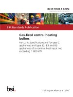
NOTE 3 Any test circuit corresponding to that of Figure 1 can be used to make the measurement of EBLF. The
luminous flux of a lamp is usually measured with an integrating photometer. For ratio measurements of luminous
fluxes, a suitable illuminance meter is sufficient as there is a close relationship between luminous flux and
illumination at a fixed point.
NOTE 4 Other methods may apply for determining EBLF, in particular methods which permanently record the
luminous flux of the lamp associated to the ballast under test.
BS EN 61347-2-7:2012
61347-2-7 â IEC:2011
15
A
(I)
r
(r)
r
(r)
mV
1
3
2
V
4
5
àA
6
A
7
W
V
V
8
IEC 2656/11
Key
1
Supply
2
Ballast under test
3
Thermocouple
4
Reference lamp
5
Photocell
6
Current transformer
7
Supply
8
Reference ballast
Figure 1 – Suitable circuit for the measurement
of lamp current and luminous flux
21 Changeover operation
Changeover from normal to emergency mode shall occur at not less than 0,6 times rated
supply voltage. It shall not occur at greater than 0,85 times rated supply voltage.
The normal mains supply to the ballast shall be reduced within 0,5 s to 0,6 times rated voltage
after which the emergency lamps shall operate.
The ballast shall be switched off and on 500 times, each cycle consisting of 2 s off and 2 s on
(at 0,85 times the rated supply voltage), throughout these cycles and on completion the
ballast shall operate the emergency lamp when switched into emergency mode operation.
NOTE 1 It may be necessary to ensure that batteries are not fully discharged before completion of this test.
Additional charging periods may be required.
For ballasts with rest mode facility, changeover from rest mode to normal mode shall occur
automatically at not greater than 0,9 times the rated supply voltage. In this case, the switching
test is carried out as above but with the off cycle extended to 3 s minimum, with the rest mode
command sent to the ballast after 2 s following the off periods in the 500 switching cycles.
The off period time shall be as short as possible to ensure the operation of the rest mode
facility.
BS EN 61347-2-7:2012
61347-2-7 © IEC:2011
– 16 –
NOTE 2 In Japan, changeover from normal to emergency mode at not less than 0,4 times rated supply voltage is
accepted.
22 Recharging device
The recharging device, if provided, shall provide the rated charge performance as declared by
the controlgear manufacturer to charge the battery within 24 h over the rated ambient
temperature range and when operating at voltages within the range of 0,9 times the rated
operating voltage (range) and 1,06 times the rated operating voltage (range).
Transformers built into controlgears for self-contained emergency luminaires for charging the
batteries shall comply with the relevant requirements of IEC 61558-2-1:2009,
IEC 61558-2-6:2009 and IEC 61558-2-16:2009, these requirements being specified in 4.2 and
5.13 of IEC 61558-1:2005+Amendment 1:2009.
The output voltage of the recharging device shall not exceed 50 V d.c. during operation with
or without the batteries connected.
Compliance is checked by the tests of 22.1 to 22.5.
22.1 Low temperature operation –The battery shall be charged for 48 h and then discharged
until the voltage indicated in Table 1 is achieved.
Table 1 – Voltage per cell to which the battery is discharged
Discharge condition/cell
V
Battery type
Duration: 1 h
Duration: 3 h
Nickel cadmium
1,0
1,0
Lead acid
1,75
1,80
Nickel metal hydride
1,0
1,0
The values apply at an ambient temperature of (20 ± 5) °C and the preferred duration
specified in A.4.2 d) and A.5.2 c) of IEC 60598-2-22.
The recharging device shall then be operated to charge the fully discharged battery at
0,9 times rated supply voltage and the minimum of the declared ambient temperature range of
the controlgear (if not declared, at room temperature), for a period of 24 h.
During the test, all parts, including batteries and lamps, shall be placed within the test
cabinet. Where the ambient temperature rating limit of the test battery is different from that
declared for the ballast then the battery should be held separately at its own minimum
declared temperature rating.
Normal lighting supply failure shall then be simulated and the battery shall operate the lamp
from the controlgear for the rated duration of the operation. At the end of the rated duration,
the measured battery voltage shall be at least V min as specified in Clause 20.
Compliance shall be checked by measurement.
BS EN 61347-2-7:2012
61347-2-7 © IEC:2011
– 17 –
22.2 High temperature operation – The test of 22.1 is repeated at 0,9 times the rated
operating voltage but at the maximum of the declared ambient temperature range.
Normal lighting supply failure shall then be simulated and the battery shall operate the lamp
from the controlgear for the rated duration of the operation. At the end of the rated duration,
the measured battery voltage shall be at least V min as specified in Clause 20.
During the test, all parts, including batteries and lamps, shall be placed within the test
cabinet. Where the ambient temperature rating limit of the test battery is different from that
declared for the ballast, then the battery should be held separately at its own maximum
declared temperature rating.
Compliance shall be checked by measurement.
22.3 Abnormal operating condition – The recharging device shall be operated at 1,1 times
rated supply voltage and the maximum of the declared ambient temperature range with the
batteries disconnected and replaced by a short circuit link. The test shall continue until stable
conditions are achieved or a protective device (e.g. fuse or thermal link) operates.
There shall be no emission of flames or molten material, or production of flammable gases
from the recharging device.
On completion of the test period, the short circuit link shall be removed, the battery shall be
reconnected and user replaceable fuse links replaced where necessary. The recharging
device shall remain safe. In the case of chargers containing self-resetting or user-replaceable
protective devices, normal battery recharge shall occur
22.4 Maximum output voltage – The output voltage of the recharging device shall not exceed
50 V d.c. when operated at 1,1 times the rated supply voltage with and without the batteries
connected.
Compliance shall be checked by measurement.
22.5 Battery charge and discharge characteristics – The test of Subclause 22.1 is repeated
at 0,9 and 1,1 times the rated operating voltage but under reference operating ambient
temperature characteristics of 25 °C ± 2 °C.
During both charge and discharge cycles, the current and voltage characteristics applied to
the battery shall be within those declared by the ballast manufacturer, as required by
Subclause 7.2 of this standard.
Compliance shall be checked by measurement.
22.6 Lamp failure – Any lamp failure (emergency or normal operating lighting lamps) shall
not interrupt the charging current to the battery and shall not cause an overload that could
impair the operation of the battery.
Compliance is checked by removal of the lamp during battery charging. Testing is conducted
under rated supply voltage conditions and at 25 °C ± 2 °C.
NOTE In Japan, JIL5501 and JIL5502 2 are used as application standards of the Building Law and Fire and
Disaster Management Act instead of Subclauses 22.1 to 22.5.
—————————
2 JIL5501, Specification of luminaires for emergency lighting (escape lighting)
JIL5502, Basic requirements for luminaires and active system for escape lighting
– 18 –
BS EN 61347-2-7:2012
61347-2-7 © IEC:2011
23 Protection against excessive discharge
Controlgear utilizing lead-acid batteries, and controlgear utilizing a battery of three or more
nickel cadmium cells in series, or a battery of one or more NiMH cells, shall be protected
against polarity reversal of individual cells. This protection shall be achieved by the
incorporation of an electrical system that limits further battery discharge to the current
specified below when the battery voltage has fallen to V low , determined below in a) to c).
NOTE
This provision is intended to avoid an irreversible capacity loss due to a deep discharge of cells.
a) For lead-acid batteries:
–
V low = X·n
where n is the number of cells.
X = 1,6 V for 1 h duration or less;
X = 1,7 V for greater than 1 h duration;
–
I ≤ 10 –5 × C20A where C20 is the battery capacity in ampere hours for a 20 h constant
current discharge.
This requirement applies to all emergency controlgear utilizing a lead-acid battery regardless
of the number of cells.
b) For nickel-cadmium batteries:
–
V low = X·n
where n is the number of cells.
X = 0,8 V for all duration values.
–
I ≤ 0,0015 × C5A where C5 is the battery capacity in ampere hours for 5 h constant
current discharge.
This requirement applies only to emergency controlgear utilizing a battery of three or more
nickel cadmium cells in series.
c) For NiMh batteries:
–
V low = X·n
where n is the number of cells;
X = 0,8 V for all duration values.
If a higher value is specified by the battery manufacturer in the technical data sheet, this
value will have to be applied for X.
–
I ≤25 × 10 –6 C5A, or
–
I ≤1 × 10 –3 C5A during the first 72 h and then 5 × 10 –6 C5A, where C5 is the battery
capacity in ampere hours for 5 h constant current discharge.
This requirement applies to all emergency controlgear utilizing a nickel metal hydride battery
regardless of the number of cells.
The protection system shall prevent any further discharge of the batteries by a lamp or
inverter, even where a battery voltage rise due to natural regeneration occurs, until the
normal supply has been restored.
Compliance is checked by following test.
Following a full charge cycle (24 h at rated voltage), the battery voltage and discharge current
are measured during an emergency mode cycle to full discharge (or battery cut-off switching).
The battery voltage shall not fall below V low and the discharge current shall not exceed that
specified above. Testing is conducted at 25 °C ± 2 °C.
BS EN 61347-2-7:2012
61347-2-7 © IEC:2011
– 19 –
24 Indicator
If the ballast has an indicator incorporated or associated, it shall comply with the requirements
of 22.6.7 of IEC 60598-2-22.
Compliance is checked by inspection.
25 Remote control, rest mode, inhibition mode
NOTE
A description of rest mode and inhibition mode function is given in Annex D of IEC 60598-2-22.
25.1 There shall be no switch between the battery and emergency lighting lamps other than
the changeover device.
Controlgear shall not contain any manual or non-self-resetting switch isolating the emergency
circuit(s) from the mains supply other than rest mode or inhibition mode testing facilities.
25.2 Controlgear with a rest mode facility shall be provided with either a control device or a
means of connection of a remote facility for changing from emergency mode to rest mode. In
the event of restoration of the normal supply, operation shall automatically revert to normal
mode.
Controlgear intended for use with remote inhibiting facilities shall be provided with a means of
connection to the remote inhibiting circuit.
Compliance is checked by inspection.
25.3 The operation of controlgear with a remote inhibiting facility in the emergency mode
shall not be influenced by a short circuit or a contact to earth in the wiring to a remote control
device.
Compliance is checked by simulation of these wiring faults in conjunction with the test of 28.2.
25.4 The operation of a remote control device for controlgear with rest mode or remote
inhibiting facilities provided with the controlgear shall be independent of the battery of the
controlgear and the normal mains supply.
Compliance is checked by inspection.
25.5 The operation of controlgear with rest mode facility in the emergency mode shall not be
influenced by a short-circuit, a contact to earth or an interruption in the wiring to a remote
control changeover device.
Compliance is checked by simulating these wiring faults in conjunction with the tests given
in 28.2.
– 20 –
BS EN 61347-2-7:2012
61347-2-7 © IEC:2011
25.6 In controlgear with a rest mode or inhibiting facility, the current drain from the batteries
with the controlgear in rest mode shall not exceed the following:
–
for lead-acid batteries 4 × 10 –5 × C20A where C20 is the battery capacity in ampere hours
for a 20 h constant current discharge;
–
for nickel-cadmium batteries 0,0015 × C5A where C5 is the battery capacity in ampere
hours for a 5 h constant current discharge;
–
for nickel-metal hydride batteries 10 –3 × C5A where C5 is the battery capacity in ampere
hours for a 5 h constant current discharge. It is furthermore limited to a maximum period of
time of 21 days. Beyond this period, the current shall not exceed 25 × 10 –6 × C5A. If the
residual current consumed on the battery when in rest mode is lower than 1 × 10 –3 × C5A,
the maximum period of time of 21 days can be increased proportionally as necessary.
Compliance is checked by measurement of the battery discharge current with the controlgear
in the rest mode following a full battery charge cycle (24 h at rated supply voltage). Testing is
conducted at 25 °C ± 2 °C.
NOTE
The quantity of electricity consumed within 21 days at a rate of 1 × 10 -3 C5A includes cell self-discharging.
26 Temperature cycling test and endurance test
The controlgear shall operate satisfactorily during service.
Compliance shall be checked by the following tests.
The ballast shall be mounted in accordance with the manufacturer’s instructions (including
heat sinks, if specified), operated in association with appropriately rated lamp(s) at the
maximum voltage of the rated voltage range and subjected to a temperature cycling test and
an endurance test, as follows.
a) The temperature cycling test shall be carried out, starting at the lower limit of the ambient
temperature range for 1 h. The temperature shall then be raised to the upper limit of the
ambient temperature range and maintained there for 1 h. Five such temperature cycles
shall be carried out.
b) The endurance test shall be carried out at the ambient temperature which produces t c for
a period of 50 h.
At the end of this time, and after cooling to room temperature, the controlgear shall restart
and operate the lamps at its rated operating voltage.
27 Polarity reversal
When the ballast is declared to be proof against supply voltage polarity reversal, it shall be
capable to operate with reverse voltage for 1 h.
Compliance is checked by operating ballast at reversed polarity for 1 h at the maximum d.c.
operating voltage and with appropriate lamp(s). At the end of this test period, the supply shall
be connected correctly and the lamp shall start and operate normally.
BS EN 61347-2-7:2012
61347-2-7 © IEC:2011
– 21 –
28 Fault conditions
28.1 The requirements of Clause 14 of IEC 61347-1 apply.
28.2 The operation of controlgear in the emergency mode shall not be influenced by a shortcircuit, a contact to earth or an interruption in the wiring of the normal supply to the
controlgear.
Compliance is checked by simulation of these supply wiring faults during emergency mode
operation. The controlgear shall function normally during the test.
29 Construction
The requirements of Clause 15 of IEC 61347-1 apply together with the following:
29.1.1 If applicable or if the devices in question are provided, 22.6.1, 22.6.7, 22.6.9, 22.6.11,
22.6.19 and 22.20 of IEC 60598-2-22 shall be complied with.
NOTE For the design of controlgear, the manufacturer should, in addition, keep in mind that Clauses 22.16 and
22.18 of IEC 60598-2-22 apply to a complete luminaire. As the tests in question cannot be made without a
complete luminaire, no requirements in that respect are included in this standard (except for 22.16.1).
29.1.2 A ballast supplied with batteries shall incorporate a battery that meets the
requirements of Annex I and is designed for at least 4 years of normal operation. This battery
shall be used only for emergency related functions within the luminaire or its satellite(s).
Compliance is checked by inspection and the tests specified in Annex I.
30 Creepage distances and clearances
The requirements of Clause 16 of IEC 61347-1 apply.
31 Screws, current-carrying parts and connections
The requirements of Clause 17 of IEC 61347-1 apply.
32 Resistance to heat, fire and tracking
The requirements of Clause 18 of IEC 61347-1 apply.
33 Resistance to corrosion
The requirements of Clause 19 of IEC 61347-1 apply.
34 Abnormal lamp conditions
34.1 Controlgear shall not impair safety when operated under abnormal lamp conditions.
34.2 Abnormal conditions for controlgear for fluorescent lamps
Compliance is checked by the following test.
– 22 –
BS EN 61347-2-7:2012
61347-2-7 © IEC:2011
Each of the following conditions shall be applied with the ballast operating according to the
manufacturer’s instructions (including a heat sink, if specified) for 1 h:
a) the lamp or one of the lamps is not inserted;
b) the lamp does not start because one of the cathodes is broken;
c) the lamp does not start although the cathode circuits are intact (de-activated lamp);
d) the lamp operates, but one of the cathodes is de-activated or broken (rectifying effect).
For the test simulating operation with a de-activated lamp, a resistor is connected in place of
each lamp cathode. The resistor value is derived from the value of the nominal running
current of the lamp prescribed in the relevant lamp data sheet of IEC 60081 and IEC 60901
and substituted in the following equation:
R=
11,0
Ω
2,1 I n
where
I n is the rated lamp current of the lamp.
For lamps not covered by IEC 60081 and IEC 60901, the values declared by the lamp
manufacturer shall be used.
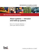
When testing electronic ballasts for the rectifying effect, the circuit shown in Figure 2a is
used.
The lamp is connected to the midpoints of the appropriate equivalent resistors. The rectifier
polarity is chosen so as to give the most unfavourable conditions. If necessary, the lamp is
started using a suitable starting device.
Ballast under test
Resistor
Lamp
Supply
Rectifier
IEC 2657/11
The rectifier characteristics shall be:
Peak inverse voltage
U RRM
≥
3 000 V
Reverse leakage current
IR
≤
10 µA
Forward current
IF
≥
three times nominal lamp running current
Reverse recovery time
(maximum frequency: 150 kHz)
t rr
≤
500 ns
(measured with I F = 0,5 A and I R = 1 A to I R = 0,25 A)
Figure 2a – Circuit for testing