Bsi bs en 61260 1 2014
Bạn đang xem bản rút gọn của tài liệu. Xem và tải ngay bản đầy đủ của tài liệu tại đây (1.8 MB, 48 trang )
BS EN 61260-1:2014
BSI Standards Publication
Electroacoustics —
Octave-band and
fractional-octave-band
filters
Part 1: Specifications
BS EN 61260-1:2014
BRITISH STANDARD
National foreword
This British Standard is the UK implementation of EN 61260-1:2014.
It is identical to IEC 61260-1:2014. Together with BS EN 61260-2 and
BS EN 61260-3 it supersedes BS EN 61260:1996, which will be withdrawn
upon publication of the rest of the series.
The UK participation in its preparation was entrusted to Technical
Committee EPL/29, Electroacoustics.
A list of organizations represented on this committee can be obtained
on request to its secretary.
This publication does not purport to include all the necessary provisions
of a contract. Users are responsible for its correct application.
© The British Standards Institution 2014.
Published by BSI Standards Limited 2014
ISBN 978 0 580 61956 4
ICS 17.140.50
Compliance with a British Standard cannot confer immunity from
legal obligations.
This British Standard was published under the authority of the Standards
Policy and Strategy Committee on 31 August 2014.
Amendments/corrigenda issued since publication
Date
Text affected
BS EN 61260-1:2014
EUROPEAN STANDARD
EN 61260-1
NORME EUROPÉENNE
EUROPÄISCHE NORM
June 2014
ICS 17.140.50
Supersedes EN 61260:1995
English Version
Electroacoustics - Octave-band and fractional-octave-band filters
- Part 1: Specifications
(IEC 61260-1:2014)
Electroacoustique - Filtres de bande d'octave et de bande
d'une fraction d'octave - Partie 1: Spécifications
(CEI 61260-1:2014)
Elektroakustik - Bandfilter für Oktaven und Bruchteile von
Oktaven - Teil 1: Anforderungen
(IEC 61260-1:2014)
This European Standard was approved by CENELEC on 2014-03-21. CENELEC members are bound to comply with the CEN/CENELEC
Internal Regulations which stipulate the conditions for giving this European Standard the status of a national standard without any alteration.
Up-to-date lists and bibliographical references concerning such national standards may be obtained on application to the CEN-CENELEC
Management Centre or to any CENELEC member.
This European Standard exists in three official versions (English, French, German). A version in any other language made by translation
under the responsibility of a CENELEC member into its own language and notified to the CEN-CENELEC Management Centre has the
same status as the official versions.
CENELEC members are the national electrotechnical committees of Austria, Belgium, Bulgaria, Croatia, Cyprus, the Czech Republic,
Denmark, Estonia, Finland, Former Yugoslav Republic of Macedonia, France, Germany, Greece, Hungary, Iceland, Ireland, Italy, Latvia,
Lithuania, Luxembourg, Malta, the Netherlands, Norway, Poland, Portugal, Romania, Slovakia, Slovenia, Spain, Sweden, Switzerland,
Turkey and the United Kingdom.
European Committee for Electrotechnical Standardization
Comité Européen de Normalisation Electrotechnique
Europäisches Komitee für Elektrotechnische Normung
CEN-CENELEC Management Centre: Avenue Marnix 17, B-1000 Brussels
© 2014 CENELEC All rights of exploitation in any form and by any means reserved worldwide for CENELEC Members.
Ref. No. EN 61260-1:2014 E
BS EN 61260-1:2014
EN 61260-1:2014
-2-
Foreword
The text of document 29/835/FDIS, future edition 1 of IEC 61260-1, prepared by IEC/TC 29
"Electroacoustics" was submitted to the IEC-CENELEC parallel vote and approved by CENELEC as
EN 61260-1:2014.
The following dates are fixed:
•
latest date by which the document has
to be implemented at national level by
publication of an identical national
standard or by endorsement
(dop)
2014-12-21
•
latest date by which the national
standards conflicting with the
document have to be withdrawn
(dow)
2017-03-21
This document supersedes EN 61260:1995.
EN 61260-1:2014 includes the following significant technical changes with respect to EN 61260:1995:
a) the single document in the first edition of EN 61260:1995 is in EN 61260 series
separated into the three parts covering: specifications, pattern evaluation tests and
periodic tests;
b) the EN 61260:1995 specified three performance categories: classes 0, 1 and 2. The
EN 61260 series specifies requirements for class 1 and 2;
c) in the EN 61260:1995, the design goals for the specification can be based on base-2 or
base 10 design. In EN 61260 series only base-10 is specified;
d) the reference environmental conditions have been changed from 20 °C / 65 % RH to
23 °C / 50 % RH;
e) EN 61260:1995 specified tolerance limits without considering the uncertainty of
measurement for verification of the specifications. EN 61260 series specifies acceptance
limits for the observed values and maximum-permitted uncertainty of measurements for
laboratories testing conformance to specifications in the standard.
Attention is drawn to the possibility that some of the elements of this document may be the subject of
patent rights. CENELEC [and/or CEN] shall not be held responsible for identifying any or all such
patent rights.
Endorsement notice
The text of the International Standard IEC 61260-1:2014 was approved by CENELEC as a European
Standard without any modification.
In the official version, for Bibliography, the following notes have to be added for the standards indicated:
CISPR 16-1-1:2010
NOTE
Harmonised as EN 55016-1-1:2010.
-3-
BS EN 61260-1:2014
EN 61260-1:2014
Annex ZA
(normative)
Normative references to international publications
with their corresponding European publications
The following documents, in whole or in part, are normatively referenced in this document and are
indispensable for its application. For dated references, only the edition cited applies. For undated
references, the latest edition of the referenced document (including any amendments) applies.
NOTE 1 When an International Publication has been modified by common modifications, indicated by (mod), the relevant
EN/HD applies.
NOTE 2 Up-to-date information on the latest versions of the European Standards listed in this annex is available here:
www.cenelec.eu
Publication
IEC 61000-4-2
Year
-
IEC 61000-4-3
2006
IEC 61000-6-1
2005
IEC 61000-6-2
2005
IEC 61000-6-3
2006
IEC 61672-1
-
ISO/IEC Guide 98-3 ISO/IEC Guide 98-4 2012
CISPR 22 (mod)
2008
Title
EN/HD
Electromagnetic compatibility (EMC) -- Part EN 61000-4-2
4-2: Testing and measurement techniques
- Electrostatic discharge immunity test
Electromagnetic compatibility (EMC) -- Part EN 61000-4-3
4-3: Testing and measurement techniques
- Radiated, radio-frequency,
electromagnetic field immunity test
Electromagnetic compatibility (EMC) -- Part EN 61000-6-1
6-1: Generic standards - Immunity for
residential, commercial and light-industrial
environments
Electromagnetic compatibility (EMC) -- Part EN 61000-6-2
6-2: Generic standards - Immunity for
industrial environments
+
Electromagnetic compatibility (EMC) -- Part EN 61000-6-3
6-3: Generic standards - Emission
standard for residential, commercial and
light-industrial environments
Electroacoustics - Sound level meters -EN 61672-1
Part 1: Specifications
Uncertainty of measurement -- Part 3:
Guide to the expression of uncertainty in
measurement (GUM:1995)
Uncertainty of measurement -- Part 4: Role of measurement uncertainty in conformity
assessment
Information technology equipment - Radio EN 55022
disturbance characteristics - Limits and
methods of measurement
+AC
Year
-
2006
2007
2005
2005
2007
2010
2011
–2–
BS EN 61260-1:2014
61260-1 © IEC:2014
CONTENTS
INTRODUCTION ................................................................................................................... 6
1
Scope ............................................................................................................................ 7
2
Normative references..................................................................................................... 7
3
Terms and definitions .................................................................................................... 8
4
Reference environmental conditions ............................................................................. 12
5
Performance requirements ........................................................................................... 12
5.1
5.2
5.3
5.4
5.5
5.6
5.7
5.8
5.9
5.10
5.11
5.12
5.13
5.14
5.15
5.16
5.17
5.18
5.19
5.20
5.21
5.22
6
General .......................................................................................................... 12
Octave frequency ratio ................................................................................... 13
Reference frequency ...................................................................................... 13
Exact mid-band frequencies ........................................................................... 13
Nominal mid-band frequencies ........................................................................ 13
Band-edge frequencies ................................................................................... 14
Time-averaged signal levels ........................................................................... 14
Filter attenuation ............................................................................................ 14
Reference attenuation .................................................................................... 15
Relative attenuation ....................................................................................... 15
Normalized effective bandwidth ...................................................................... 18
Effective bandwidth deviation ......................................................................... 19
Linear operating range ................................................................................... 19
Time-invariant operation ................................................................................. 20
Anti-alias filters .............................................................................................. 20
Summation of output signals ........................................................................... 21
Overload indicator .......................................................................................... 21
Filter decay time............................................................................................. 21
Maximum input signal ..................................................................................... 21
Output terminals and terminating impedances ................................................. 22
Power supply check ....................................................................................... 22
Sensitivity to various environments ................................................................. 22
5.22.1
General ......................................................................................... 22
5.22.2
Ambient air temperature and relative humidity ................................ 22
5.23
Electrostatic-discharge and electromagnetic-compatibility requirements .......... 22
5.23.1
General ......................................................................................... 22
5.23.2
Electrostatic discharges ................................................................. 23
5.23.3
Immunity to power-frequency and radio-frequency fields ................ 23
5.23.4
Emission limits .............................................................................. 25
Instrument marking ...................................................................................................... 25
7
Instruction manual ....................................................................................................... 26
7.1
General .......................................................................................................... 26
7.2
Operation ....................................................................................................... 26
7.3
Testing ........................................................................................................... 27
Annex A (informative) Relationship between tolerance interval, corresponding
acceptance interval and the maximum-permitted uncertainty of measurement ...................... 28
Annex B (normative) Maximum-permitted expanded uncertainties of measurement ............. 29
Annex C (informative) Examples of conformance assessment to specifications of this
standard ............................................................................................................................. 30
BS EN 61260-1:2014
61260-1 © IEC:2014
–3–
C.1
General .......................................................................................................... 30
C.2
Conformance criteria ...................................................................................... 30
C.3
Example test results ....................................................................................... 31
Annex D (informative) Base 2 filters ................................................................................... 33
Annex E (normative) Nominal mid-band frequencies ........................................................... 34
E.1
Mid-band frequencies for octave-band and one-third-octave-band filters .......... 34
E.2
Mid-band frequencies for one-half-octave-band filters ..................................... 34
E.3
Mid-band frequencies for other bandwidths ..................................................... 34
Annex F (informative) Normalized frequencies at breakpoints of acceptance limits on
minimum and maximum relative attenuation for one-third-octave-band filters ........................ 36
Annex G (informative) Filter response to exponentially swept sinusoidal signals .................. 38
G.1
Exponential frequency sweep ......................................................................... 38
G.2
Response of set of band-pass filters to a sweep .............................................. 38
Annex H (informative) Measurement of filter decay time ...................................................... 41
H.1
H.2
General .......................................................................................................... 41
Measurement of filter decay time .................................................................... 41
H.2.1
Instruments with the capability to measure reverberation time ........ 41
H.2.2
Instruments without the capability to measure reverberation
time .............................................................................................. 41
Bibliography ....................................................................................................................... 43
Figure 1 – Minimum and maximum limits on relative attenuation as a function of f/f m
for class 1 and class 2 octave-band filters ........................................................................... 17
Figure A.1 – Relationship between tolerance interval, corresponding acceptance
interval and the maximum-permitted uncertainty of measurement ......................................... 28
Figure C.1 – Examples of conformance assessment ............................................................ 32
Figure G.1 – Relation between the logarithmic frequency scale and the linear time
scale due to the exponential sweep ..................................................................................... 40
Table 1 – Acceptance limits on relative attenuation for octave-band filters ........................... 15
Table 2 – Limits for radiated disturbance of class B Information Technology Equipment
(ITE) at a distance of 10 m .................................................................................................. 25
Table 3 – Limits for conducted disturbance to the voltage of a public supply of electric
power ................................................................................................................................. 25
Table B.1 – Maximum-permitted expanded uncertainties of measurement ............................ 29
Table C.1 – Examples of conformance assessment ............................................................. 31
Table E.1 – Mid-band frequencies for octave-band and one-third-octave-band filters in
the audio range .................................................................................................................. 35
Table F.1 – Acceptance limits on relative attenuation for one-third-octave-band filters .......... 37
–6–
BS EN 61260-1:2014
61260-1 © IEC:2014
INTRODUCTION
IEC 61260:1995 and its Amendment 1:2001 are now separated into the following three parts
of IEC 61260 series:
•
Part 1: Specifications
•
Part 2: Pattern evaluation tests (under consideration)
•
Part 3: Periodic tests (under consideration)
For assessments of conformance to performance specifications, IEC 61260-1 uses different
criteria than were used for the IEC 61260:1995 edition.
IEC 61260:1995 did not provide any requirements or recommendations to account for the
uncertainty of measurement in assessments of conformance to specifications. This absence
of requirements or recommendations to account for uncertainty of measurement created
ambiguity in determinations of conformance to specifications for situations where a measured
deviation from a design goal was close to a limit of the allowed deviation. If conformance was
determined based on whether a measured deviation did or did not exceed the limits, the enduser of the octave-band and fractional-octave-band filters incurred the risk that the true
deviation from a design goal exceeded the limits.
To remove this ambiguity, IEC Technical Committee 29, at its meeting in 1996, adopted a
policy to account for measurement uncertainty in assessments of conformance in International
Standards that it prepares.
This first edition of IEC 61260-1 uses an amended criterion for assessing conformance to a
specification. Conformance is demonstrated when (a) measured deviations from design goals
do not exceed the applicable acceptance limits and (b) the uncertainty of measurement does
not exceed the corresponding maximum-permitted uncertainty. Acceptance limits are
analogous to the tolerance limits allowances for design and manufacturing implied in the
IEC 61260:1995.
Actual and maximum-permitted uncertainties of measurement are determined for a coverage
probability of 95 %. Unless more-specific information is available, the evaluation of the
contribution of a specific filter or filter set to a total measurement uncertainty can be based on
the acceptance limits and maximum-permitted uncertainties specified in this standard.
BS EN 61260-1:2014
61260-1 © IEC:2014
–7–
ELECTROACOUSTICS –
OCTAVE-BAND AND FRACTIONAL-OCTAVE-BAND FILTERS –
Part 1: Specifications
1
Scope
1.1
This part of the IEC 61260 series specifies performance requirements for analogue,
sampled-data, and digital implementations of band-pass filters. The extent of the pass-band
region of a filter's relative attenuation characteristic is a constant percentage of the exact midband frequency for all filters of a given bandwidth. An instrument conforming to the
requirements of this standard may contain any number of contiguous band-pass filters
covering any desired frequency range.
1.2
Performance requirements are provided for two filter classes: class 1 and class 2. In
general, specifications for class 1 and class 2 filters have the same design goals and differ
mainly in the acceptance limits and the range of operational temperature. Acceptance limits
for class 2 are greater than, or equal to, those for class 1. Maximum-permitted expanded
uncertainties of measurement are also specified.
1.3
Performance requirements are given for designs where the octave frequency ratio and
the mid-band frequencies are powers of ten.
1.4
Band-pass filters conforming to the performance requirements of this standard may be
part of various measurement systems or may be an integral component of a specific
instrument such as a spectrum analyser.
1.5
This standard specifies the ranges of environmental conditions for operation of the
filters. The required range depends on whether the instrument containing the filters is
designed to be operated in a controlled environment or more generally in the field.
1.6
Band-pass filters conforming to the requirements of this standard are capable of
providing frequency-band-filtered spectral information for a wide variety of signals, for
example, time-varying, intermittent or steady; broadband or discrete frequency; and long or
short durations.
2
Normative references
The following documents, in whole or in part, are normatively referenced in this document and
are indispensable for its application. For dated references, only the edition cited applies. For
undated references, the latest edition of the referenced document (including any
amendments) applies.
IEC 61000-4-2, Electromagnetic compatibility (EMC) – Part 4-2: Testing and measurement
techniques – Electrostatic discharge immunity test
IEC 61000-4-3:2006, Electromagnetic compatibility (EMC) – Part 4-3: Testing and
measurement techniques – Radiated, radio-frequency, electromagnetic field immunity test
IEC 61000-6-1:2005, Electromagnetic compatibility (EMC) – Part 6-1: Generic standards –
Immunity for residential, commercial and light-industrial environments
–8–
BS EN 61260-1:2014
61260-1 © IEC:2014
IEC 61000-6-2:2005, Electromagnetic compatibility (EMC) – Part 6-2: Generic standards –
Immunity for industrial environments
IEC 61000-6-3:2006, Electromagnetic compatibility (EMC) – Part 6-3: Generic standards –
Emission standard for residential, commercial and light-industrial environments
Amendment 1:2010
IEC 61672-1, Electroacoustics – Sound level meters – Part 1: Specifications
CISPR 22:2008, Information technology equipment – Radio disturbance characteristics –
Limits and methods of measurement
ISO/IEC Guide 98-3, Uncertainty of measurement – Part 3: Guide to the expression of
uncertainty in measurement (GUM: 1995)
ISO/IEC Guide 98-4:2012, Uncertainty of measurement – Part 4: Role of measurement
uncertainty in conformity assessment
3
Terms and definitions
For the purposes of this document, the terms and definitions given in IEC 61000-4-2,
IEC 61000-4-3, IEC 61000-6-1, IEC 61000-6-2, and IEC 61000-6-3, as well as the following
apply.
3.1
band-pass filter
filter with a single transmission band (or pass-band with small relative attenuation) extending
from a lower band-edge frequency greater than zero to a finite upper band-edge frequency
3.2
octave frequency ratio
frequency ratio nominally equal to an octave or a frequency ratio of 2:1
Note 1 to entry:
5.2.1 gives the expression of the octave frequency ratio for this standard.
3.3
bandwidth designator
reciprocal of a positive integer, including 1, to designate the fraction of an octave band
Note 1 to entry: The bandwidth designator is used to designate the nominal bandwidth of the filters in a set of
filters, for example, for 1/b = 1/12, the filters are designated as one-twelfth-octave-band filters.
3.4
reference frequency
single frequency selected to normalize the attenuation response for all band-pass filters in a
filter set
Note 1 to entry:
The reference frequency is expressed in hertz (Hz).
3.5
exact mid-band frequency
frequency that has a specified relationship to the reference frequency such that the ratio of
the exact mid-band frequencies of any two contiguous band-pass filters is the same for all
filters in a filter set of a specified bandwidth
Note 1 to entry:
Exact mid-band frequency is expressed in hertz (Hz).
BS EN 61260-1:2014
61260-1 © IEC:2014
–9–
3.6
nominal mid-band frequency
rounded mid-band frequency for the designation of band-pass filters
Note 1 to entry:
Nominal mid-band frequency is expressed in hertz (Hz).
3.7
normalized frequency
for a band-pass filter, ratio of a frequency to the corresponding exact mid-band frequency
3.8
band-edge frequencies
frequencies at the lower and upper edges of the pass-band of a band-pass filter such that the
exact mid-band frequency is the geometric mean of the lower and upper band-edge
frequencies
Note 1 to entry:
Band-edge frequencies are expressed in hertz (Hz).
3.9
normalized bandwidth of a filter
relative bandwidth for a given filter, the ratio of the upper band-edge frequency minus the
corresponding lower band-edge frequency to the exact mid-band frequency
3.10
octave-band filter
band-pass filter for which the ratio of upper band-edge frequency to lower band-edge
frequency is the octave frequency ratio
3.11
fractional-octave-band filter
band-pass filter for which the ratio of upper band-edge frequency to lower band-edge
frequency is the octave frequency ratio raised to an exponent equal to the applicable
bandwidth designator
Note 1 to entry:
An octave-band filter is also a fractional-octave-band filter (1/b = 1/1).
3.12
signal level
time-average signal level
at any frequency, ten times the logarithm to the base ten of the ratio of a specified time-meansquare signal to the square of a specified reference value
Note 1 to entry
Time-averaged signal level is expressed in decibels (dB).
3.13
filter attenuation
at any frequency, for a band-pass filter, the input signal level minus the corresponding output
signal level
Note 1 to entry:
Filter attenuation is expressed in decibels (dB).
3.14
reference attenuation
for all band-pass filters in an instrument, nominal filter attenuation in the pass-band for
determining relative attenuation
Note 1 to entry:
Reference attenuation is expressed in decibels (dB).
3.15
relative attenuation
filter attenuation minus the reference attenuation
BS EN 61260-1:2014
61260-1 © IEC:2014
– 10 –
Note 1 to entry:
Relative attenuation is expressed in decibels (dB).
3.16
normalized response
at any normalized frequency, the anti-logarithm to the base ten of minus one-tenth of the
corresponding relative attenuation
3.17
normalized effective bandwidth
integral over normalized frequency of the normalized response of a band-pass filter to
constant-amplitude sinusoidal input signals, the normalized response being weighted with the
inverse of the normalized frequency
3.18
normalized reference effective bandwidth
normalized effective bandwidth for a band-pass filter having zero relative attenuation in the
passband and infinite relative attenuation at other frequencies
3.19
effective bandwidth deviation
ten times the logarithm to the base ten of the ratio of the normalized effective bandwidth of a
filter to the normalized reference effective bandwidth
Note 1 to entry:
Effective bandwidth deviation is expressed in decibels (dB).
3.20
reference level range
one of the available level ranges specified for
characteristics of the band-pass filters in a filter set
testing the electrical
performance
3.21
reference input signal level
specified reference level of the input signal on the reference level range
Note 1 to entry:
The reference input signal level is expressed in decibels (dB).
3.22
level linearity deviation
on any level range at the exact mid-band frequency, if not otherwise specified, an indicated
output signal level minus the anticipated output signal level
Note 1 to entry:
Level linearity deviation is expressed in decibels (dB).
3.23
linear operating range
for a stated filter and a stated level range, the extent of steady sinusoidal input signal levels
over which level linearity deviations do not exceed the applicable limits of this standard
Note 1 to entry:
Linear operating range is expressed in decibels (dB).
3.24
level range control
device for adjusting the sensitivity of a band-pass filter in response to changes in the level
of the input signal in order to maintain the overall operation of the filter within the linear
operating range
3.25
measurement range
for any exact mid-band frequency, the range from the lower boundary of the input signal
level for the linear operating range on the most-sensitive level range to the upper boundary
of the input signal level for the linear operating range on the least-sensitive level range
BS EN 61260-1:2014
61260-1 © IEC:2014
Note 1 to entry:
– 11 –
A measurement range is expressed in decibels (dB).
3.26
analogue filter
filter that operates continuously on an input signal to produce a filtered output
3.27
sampled-data filter
computational process that operates on samples of an input signal to produce a filtered
output
3.28
digital filter
subset of sampled-data filters that operates on digitized samples of input data
3.29
time-invariant operation
operational mode or capability of a system of band-pass filters such that the response to a
signal is independent of the time when the signal was applied
3.30
filter decay time
at a stated frequency, elapsed time required for the output signal level to decrease by 60 dB
after sudden cessation of the signal from the input to the filter
Note 1 to entry:
Filter decay time is expressed in seconds (s).
3.31
reference orientation
orientation of a band-pass filter with respect to the principal direction of an emitter or receiver
of radio-frequency fields
3.32
group X band-pass filter
self-contained instrument that includes band-pass filtering facilities conforming to the
requirements of this standard and which specifies internal battery power for the normal mode
of operation and requiring no external connection to other apparatus to operate the instrument
3.33
group Y band-pass filter
self-contained instrument that includes band-pass filtering facilities conforming to the
requirements of this standard and which specifies connection to a public supply of electrical
power for the normal mode of operation and also requiring no external connection to other
apparatus to operate the instrument
3.34
group Z band-pass filter
instrument that includes band-pass filtering facilities conforming to the requirements of this
standard and requiring two or more items of equipment to be connected together by some
means for the normal mode of operation, with operation either from batteries or from a public
supply of electrical power
Note 1 to entry: If the items communicate by means of radio or optical methods, but are not connected by any
conductive device, the items are not connected in this context.
3.35
coverage probability
probability that the set of true quantity values of a measurand is contained within a specified
coverage interval
– 12 –
BS EN 61260-1:2014
61260-1 © IEC:2014
[SOURCE: ISO/IEC Guide 98-4:2012, 3.2.8]
3.36
acceptance limit
specified upper or lower bound of permissible measured quantity values
[SOURCE: ISO/IEC Guide 98-4:2012, 3.3.8]
4
Reference environmental conditions
Reference environmental conditions are as follows:
•
temperature
23 °C
•
static pressure
101,325 kPa
•
relative humidity
50 %
5
Performance requirements
5.1
General
5.1.1
Electrical response characteristics specified in this standard for fractional-octaveband filters apply under the reference environmental conditions of Clause 4, if not otherwise
stated.
5.1.2
Any filter design realization may be utilized provided the resulting filters conform to
all applicable requirements of this standard.
5.1.3
Band-pass filters may be powered by batteries or from external power supply
systems.
5.1.4
The configuration of the filter shall be as specified in the Instruction Manual for one
of the normal modes of operation, including required accessories.
5.1.5
For filters enclosed in a sound level meter with detachable preamplifier, the signal
input to the filter may be, as specified by the supplier, the input of the preamplifier through a
suitable input device replacing the microphone, or the terminal where the signal from the
preamplifier normally is connected.
5.1.6
aging.
Acceptance limits in this standard include allowances for design, manufacturing and
5.1.7
In subsequent subclauses, acceptance limits are provided for allowable values of
measured deviations from design goals. Annex A describes the relationship between
tolerance interval, corresponding acceptance interval and the maximum-permitted uncertainty
of measurement.
5.1.8
For pattern-evaluation tests and periodic tests, the laboratory shall determine that
their actual expanded uncertainties, as the 95 % coverage intervals in accordance with
ISO/IEC Guide 98-3 and ISO/IEC Guide 98-4, do not exceed the maximum-permitted
expanded uncertainties specified in Annex B.
5.1.9
Conformance to the specifications is demonstrated when (a) the measured deviations
from the design goals do not exceed the applicable acceptance limits and (b) the
corresponding actual expanded uncertainties of measurements does not exceed the
corresponding maximum-permitted uncertainty of measurement given in Annex B.
BS EN 61260-1:2014
61260-1 © IEC:2014
– 13 –
5.1.10 Annex C gives examples of evaluation of conformance to specifications of this
standard.
5.2
Octave frequency ratio
5.2.1
For this standard, the octave frequency ratio, G, shall be given by the following
expression
G = 103/10
(1)
5.2.2
The octave frequency ratio calculated from Formula (1) to six significant digits is
1,995 26. Filters designed according to this ratio are designated base-10 filters.
NOTE 1
Filters specified in this standard are by convention called octave-band and fractional-octave band filters.
NOTE 2 For technical reasons, some filters have been designed based on G = 2, exactly. Such filter designs are
called base-2 filters. The probability that a base-2 filter conforms to the requirements of this standard decreases as
the difference between the mid-band frequency and the reference frequency increases; see Annex D.
5.3
Reference frequency
For the purposes of this standard, the reference frequency, f r , is 1 000 Hz, exactly.
5.4
Exact mid-band frequencies
5.4.1
When the denominator of the bandwidth designator is an odd number, the exact midband frequencies, f m , of any filter in a set of filters shall be determined from the following
expression
f m = f r G x/b
(2)
where f r is the reference frequency and 1/b is the bandwidth designator, for example 1/1 or
1/3 for octave-band or one-third-octave-band filters, respectively.
5.4.2
When the denominator of the bandwidth designator is an even number, exact midband frequencies of any filter in a set of filters shall be determined from the following
expression
f m = f r G (2x+1)/(2b)
(3)
where x in Formulas (2) and (3) is any integer, positive, negative or zero.
NOTE 1 The outputs of narrow-bandwidth fractional-octave-band filters that have exact mid-band frequencies
determined from Formula (2) or Formula (3) can be combined to approximate the band level indicated by a filter of
wider bandwidth with a corresponding exact mid-band frequency and corresponding band-edge frequencies.
NOTE 2 When the denominator of the bandwidth designator is an odd number, one of the filters in a complete
filter set can have a mid-band frequency of 1 000 Hz. When the denominator of the bandwidth designator is an
even number, the band-edge frequencies of an adjacent pair of filters in a complete filter set can be at 1 000 Hz
and none of the filters will have a mid-band frequency of 1 000 Hz.
5.5
Nominal mid-band frequencies
Octave-band and fractional-octave-band filters shall be identified, or labelled, by their nominal
mid-band frequencies. Annex E provides exact and nominal mid-band frequencies for octaveband and one-third-octave-band filters for the usual range of audio frequencies. Annex E also
specifies a procedure for determining the nominal mid-band frequencies for fractional-octaveband filters with other bandwidth designators.
BS EN 61260-1:2014
61260-1 © IEC:2014
– 14 –
5.6
Band-edge frequencies
5.6.1
Lower and upper band-edge frequencies for a pass-band filter shall be determined
from the following expressions:
f 1 = f m G -1/(2b)
(4)
f 2 = f m G +1/(2b)
(5)
and
where
f 1 is the lower band-edge frequency;
f 2 is the upper band-edge frequency;
G is the octave frequency ratio given by Formula (1), and
f m is an exact mid-band frequency determined from Formula (2) or Formula (3).
NOTE
by
An exact mid-band frequency is the geometric mean of the corresponding band-edge frequencies as given
fm =
f1 f 2 .
A band-edge frequency ratio is given by f 2 /f 1 = G 1/b , for example 10 3/10 for octave5.6.2
band filters and 10 1/10 for one-third-octave-band filters.
5.6.3
5.7
The normalized bandwidth of a filter is given by (f 2 – f 1 )/f m = G +1/(2b) – G -1/(2b) .
Time-averaged signal levels
5.7.1
A time-averaged signal level, L, shall be determined according to the following
expression:
T
∫
( 1 / T ) V 2 ( t )dt
L = 10lg
0
V02
dB
(6)
where
V(t)is the instantaneous signal as a function of time t,
T
is the elapsed time for integration and averaging, and
V 0 is an appropriate reference value such as 1 µV if the signal is a voltage.
5.7.2
The reference value shall be the same for the level of input signals and output
signals.
5.8
Filter attenuation
5.8.1
For any normalized frequency, Ω = f/f m , filter attenuation, A( Ω ), shall be determined
from the following expression:
A( Ω ) = L in ( Ω ) – L out ( Ω )
where
L in ( Ω ) is the time-averaged level of the input signal and
(7)
BS EN 61260-1:2014
61260-1 © IEC:2014
– 15 –
L out ( Ω )is the corresponding time-averaged level of the output signal.
5.8.2
For measurement of filter attenuation, the resolution of the indications of the levels of
the input and output signals shall be 0,1 dB or smaller.
5.9
Reference attenuation
5.9.1
The instruction manual shall specify the reference attenuation in the pass-band. The
reference attenuation shall be nominally the same for all filters of all available filter
bandwidths in a set of filters.
5.9.2
Verification of the specified reference attenuation may require that the filters be
adjusted according to a procedure described in the instruction manual.
5.10
Relative attenuation
5.10.1 Relative attenuation, ΔA( Ω )at normalized frequency Ω = f/f m , shall be determined
from the following expression:
ΔA( Ω ) = A( Ω ) – A ref
(8)
where
A ref is the reference attenuation.
5.10.2 For class 1 or class 2 octave-band filters, in the pass-band from Ω 1 to Ω 2 , the
relative attenuation of any filter shall be within the acceptance limits in Table 1 for the
minimum and maximum relative attenuations at the specified octave-band normalized
frequencies. In the stop-bands for Ω < Ω 1 and Ω > Ω 2 , the relative attenuation shall be not
less than the minimum acceptance limits in Table 1.
Table 1 – Acceptance limits on relative attenuation for octave-band filters
Normalized frequency
Ω = f/f m
G -4
Minimum and maximum acceptance limits on relative attenuation
in dB
Class 1
Class 2
Ωl
≤
+70; +∞
+60; +∞
Ωl
G -3
+60; +∞
+54; +∞
Ωl
G -2
+40,5; +∞
+39,5; +∞
Ωl
G -1
+16,6; +∞
+15,6; +∞
Ω 1-ε *
G -1/2 – ε
+1,2; +∞
+0,8; +∞
G -1/2
Ω 1+ε
*
+ε
-0,4; +5,3
-0,6; +5,8
Ωl
G -3/8
-0,4; +1,4
-0,6; +1,7
Ωl
G -1/4
-0,4; +0,7
-0,6; +0,9
Ωl
G -1/8
-0,4; +0,5
-0,6; +0,7
Ωl , Ωh
G0 = 1
-0,4; +0,4
-0,6; +0,6
Ωh
G +1/8
-0,4; +0,5
-0,6; +0,7
Ωh
G +1/4
-0,4; +0,7
-0,6; +0,9
Ωh
G +3/8
-0,4; +1,4
-0,6; +1,7
Ω 2-ε *
G +1/2 – ε
-0,4; +5,3
-0,6; +5,8
Ω 2+ε *
G +1/2 + ε
+1,2; +∞
+0,8; +∞
Ωh
G +1
+16,6; +∞
+15,6; +∞
BS EN 61260-1:2014
61260-1 © IEC:2014
– 16 –
Normalized frequency
Ω = f/f m
Minimum and maximum acceptance limits on relative attenuation
in dB
Class 1
Class 2
Ωh
G +2
+40,5; +∞
+39,5; +∞
Ωh
G +3
+60; +∞
+54; +∞
Ωh
≥ G +4
+70; +∞
+60; +∞
*
ε is any small number approaching zero in the regions around the lower and upper normalized band-edge
frequencies.
5.10.3 For a fractional-octave-band filter with bandwidth designator 1/b, the high-frequency
fractional-octave-band normalized frequency Ω h(1/b) , corresponding to a finite octave-band
relative attenuation acceptance limit for the performance class, shall be calculated for
Ω h(1/b) ≥ 1 from:
Ω h(1/b)
= 1+
G 1/(2b ) − 1
G 1/2 − 1
(Ω h(1/1) − 1)
(9)
5.10.4 For Ω < 1, the corresponding low-frequency fractional-octave-band normalized
frequency Ω l(1/b) shall be calculated from:
Ω l(1/b) = 1/ Ω h(1/b)
(10)
for the same acceptance limit on relative attenuation.
5.10.5 Annex F provides an example calculation of the normalized frequencies at the
breakpoints of Table 1 for the acceptance limits on minimum and maximum relative
attenuation for one-third-octave-band filters.
5.10.6 Between any pair of adjacent normalized breakpoint frequencies Ω a and Ω b from
Table 1 for octave-band filters, or between comparable normalized fractional-octave-band
breakpoint frequencies calculated according to Formulas (9) or (10) for fractional-octave-band
filters, the acceptance limit for relative attenuation ∆A x at normalized frequency Ω x shall be
determined by linear interpolation according to the following expression:
∆Ax ∆Aa + ( ∆Ab − ∆Aa )
=
lg( Ω x /Ωa )
lg( Ωb /Ωa )
where
∆A a
∆A b
is a relative attenuation acceptance limit at normalized frequency Ω a , and
is a relative attenuation acceptance limit at normalized frequency Ω b .
(11)
BS EN 61260-1:2014
61260-1 © IEC:2014
– 17 –
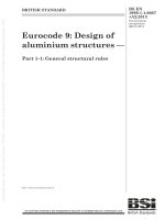
5.10.7 Figure 1 illustrates the acceptance limits on minimum and maximum relative
attenuation for octave-band filters. The figure also shows the discontinuous changes in
minimum and maximum relative attenuation at the band-edge frequencies and the linear
variation of relative attenuation limits between the breakpoint normalized frequencies
of Table 1.
–2
0
3
1
2
∆A, dB
2
4
4
6
8
10
–1
G
–0,5
0
G
0,5
G
f/fm
1
G
G
–10
0
10
∆A, dB
20
30
40
3
2
50
60
1
4
70
80
–6
G
–5
G
–4
G
–3
G
–2
G
–1
G
0
G
f/fm
1
G
2
G
3
G
4
G
5
G
6
G
IEC 0636/14
Key
x-axis: Normalized frequency f /f m – logarithmic scale.
y-axis: Relative attenuation ΔA in decibels.
1
Minimum limits on attenuation for class 1 filters
2
Maximum limits on attenuation for class 1 filters
3
Minimum limits on attenuation for class 2 filters
4
Maximum limits on attenuation for class 2 filters
Figure 1 – Minimum and maximum limits on relative attenuation
as a function of f/f m for class 1 and class 2 octave-band filters
BS EN 61260-1:2014
61260-1 © IEC:2014
– 18 –
5.11
Normalized effective bandwidth
5.11.1 The normalized response of a band-pass filter to a sinusoidal input signal shall be
given by
10
–0,1∆A(Ω)
(12)
where A( ) is the relative attenuation in decibels at normalized frequency , Formula (8).
5.11.2 In accordance with the definition 3.17, for constant-amplitude sinusoidal input
signals, normalized effective bandwidth of a band-pass filter, B e , shall be determined from
0
(1/Ω )10 - 0,1
Δ
Be
A( Ω )
dΩ
(13)
where
(1/ ) is the frequency weighting term.
In practice, the infinite range of normalized frequency in Formula (13) is replaced by a finite
range extending from a starting frequency to an ending frequency. Formula (13) is then
modified as:
Ωend
Ωstart
(1/Ω )10 - 0,1
Δ
Be
A( Ω )
dΩ
(14)
where start and end are chosen to ensure that all significant contributions to the integral are
included. Appropriate starting and ending frequencies depend on filter bandwidth and the
design of the filters.
NOTE 1 If the input signal is a series of discrete sinusoidal signals that yields a series of filter-response
measurements, the continuous integral is replaced by a summation and the integral is evaluated numerically.
NOTE 2 If the input signal is a constant-amplitude sinusoidal signal for which the frequency varies exponentially
with time, the integral expression in Formula (13) is replaced by an integral over time. Annex G provides
information related to the use of exponentially swept sinusoidal input signals.
The relation between sweep frequency, relative attenuation and the time is illustrated in
Figure G.1.
5.11.3 In accordance with the definition 3.18 and Formula (13), the normalized reference
effective bandwidth shall be given by
Br
Ω2
Ω1
(1/Ω )dΩ
ln( Ω2 / Ω1 ) ln( f 2 / f1 )
(1/b )ln(G )
(15)
where the ratio of band-edge frequencies 1 =f 1 /f m and 2 =f 2 /f m is from Formulas (4) and (5)
and ln represents natural or Napierian logarithms.
NOTE The normalized reference effective bandwidth for octave-band filters is 0,690 776 to six digits. For onethird-octave-band filters, the normalized reference effective bandwidth is 0,230 259 to six digits.
BS EN 61260-1:2014
61260-1 © IEC:2014
– 19 –
5.11.4 The normalized reference effective bandwidth is the same for all filters of a given
bandwidth in a filter set.
5.12
5.12.1
from
Effective bandwidth deviation
For a band-pass filter, the effective bandwidth deviation, ∆B, shall be determined
∆B = 10 lg (B e /B r ) dB
(16)
5.12.2 For each band-pass filter in an instrument, the acceptance limits for the effective
bandwidth deviation are ± 0,4 dB for class 1 instruments and ± 0,6 dB for class 2 instruments.
5.13
Linear operating range
5.13.1 For all filter bandwidths, and for each available level range, the linear operating
range at the exact mid-band frequency of a filter shall be at least 60 dB for class 1 filters and
at least 50 dB for class 2 filters. For each level range, the instruction manual shall state the
upper and lower boundaries of the linear operating ranges.
5.13.2 At the reference input signal level on the reference level range, the level linearity
deviation is zero.
5.13.3 For input signal levels from the upper boundary of the linear operating range to
40 dB less than the upper boundary, the acceptance limits for the level linearity deviation are
± 0,5 dB for class 1 filters or ± 0,6 dB for class 2 filters. These acceptance limits on level
linearity deviation apply on all level ranges that are available.
5.13.4 For input signal levels from 40 dB less than the upper boundary to the lower
boundary of the linear operating range, the acceptance limits for the level linearity deviation
shall not exceed ± 0,7 dB for class 1 filters or ± 0,9 dB for class 2 filters. These acceptance
limits on level linearity deviation apply on all level ranges that are available.
NOTE Deviations that can be introduced by the level range control, if provided, are included in the acceptance
limits for level linearity deviations.
5.13.5 Level ranges, if more than one is provided, shall overlap such that the linear
operating ranges overlap by at least 40 dB for class 1 filters and by at least 30 dB for class 2
filters.
5.13.6 For instruments with more than one level range, a reduced linear operating range is
allowed on the most-sensitive range, provided the most-sensitive range is not the reference
level range and also provided that the reduction in the linear operating range is stated in the
instruction manual.
5.13.7 For filters in a set of filters, each filter may have a different linear operating range
provided they have a common reference level range and reference input signal level.
NOTE Typically, filters have a common upper boundary for the linear operating range but different lower
boundaries because of the influence of electrical noise and the resolution available from the digitization process.
5.13.8 For filters where a display of the output signal is an integral component, or when the
filter output is transferred to an external display or to another measurement system, and the
range of the display is greater than the linear operating range, the instruction manual shall
state the acceptance limits on level linearity that are maintained outside the linear operating
range.
BS EN 61260-1:2014
61260-1 © IEC:2014
– 20 –
5.14
Time-invariant operation
5.14.1 The time-averaged signal level, L out , at the output of the instrument should be the
same for all filters when a constant-amplitude sinusoidal signal is applied to the input and the
frequency of the signal is varied at an exponential rate over the frequency range of all filters
of any given bandwidth.
5.14.2 For a constant-amplitude exponential-swept-frequency sinusoidal input signal, the
theoretical time-average output signal level, L c , which would be indicated at the output, shall
be determined from
Tsweep
lg( f 2 / f1)
Lc Lin − Aref + 10lg
=
Tavg lg ( f end / f start )
dB
(17)
where
L in
is the signal level of the constant-amplitude input signal;
A ref
is the reference attenuation according to 3.14 and 5.9;
T sweep
is the elapsed time required to perform an exponential frequency sweep from the
starting frequency f start , to the ending frequency f end , that is, T sweep = T end –
T start ;
f 1 and f 2
T avg
are the band-edge frequencies according to Formulas (4) and (5), and
NOTE 1
is the averaging time selected for measurement of the output signal level L out .
In Formula (17), lg(f 2 /f 1 ) equals 3/(10b).
NOTE 2 Formula (17) is an approximation that assumes that the relative attenuation is equal to the reference
attenuation in the pass-band and is infinite outside the pass-band. The sweep is assumed to be started at a
frequency sufficiently less than the lowest of the lower band-edge frequencies of the filters in a set of filters and
stopped at a frequency sufficiently above the highest of the upper band-edge frequencies in the set. The
integration time is assumed to be sufficiently long to also include time-delayed components of the output signal.
NOTE 3
Formula (17) corresponds to Formula (G.8) in Annex G and gives identical numeric results.
5.14.3 For each filter in a filter set, when the frequency is changed at a rate corresponding
to one decade in 2 s to 5 s, the acceptance limits for the deviation of a measured timeaveraged output signal level, L out , from the corresponding constant theoretical time-averaged
output signal level, L c as determined according to Formula (17), are ± 0,4 dB for class 1
instruments and ± 0,6 dB for class 2 instruments.
NOTE When the frequency increases by one decade in 2 s to 5 s, the rate, r, as given by Formula (G.2) will be in
the range 0,460 5 s -1 to 1,151 s -1 ,calculated to four significant digits.
5.14.4 The instruction manual shall state the bandwidth designators and corresponding
ranges of nominal mid-band frequencies for which the requirements of 5.14.3 apply for timeinvariant operation.
NOTE For sampled-data filters operating in real time, time-invariant operation requires that, on average, the
computations associated with each sampling interval are completed in a time period less than or equal to the
sampling interval such that all input data are processed within the sampling interval and all samples of an input
signal contribute with equal weight to the resulting filtered output signal level.
5.15
Anti-alias filters
The manufacturer shall include anti-alias filters, analogue and digital as appropriate, in a
sampled-data or digital-filter system. Anti-alias filters shall minimize interference between an
input signal and the sampling process that would cause the relative attenuation response to
exceed the minimum or the maximum acceptance limits on relative attenuation from Table 1.
BS EN 61260-1:2014
61260-1 © IEC:2014
5.16
– 21 –
Summation of output signals
For a sinusoidal input signal at any frequency between two consecutive octave or fractionaloctave mid-band frequencies, the acceptance limits for the difference between (a) the level of
the input signal minus the reference attenuation and (b) the level of the sum of the timemean-square output signals from adjacent filters of specified filter bandwidth are + 0,8 dB and
–1,8 dB for class 1 instruments and +1,8 dB and – 3,8 dB for class 2 instruments.
5.17
Overload indicator
5.17.1 A band-pass filter shall be provided with an overload indicator. The instruction
manual shall describe the operation and interpretation of overload indications.
5.17.2 An overload indication shall be displayed for sinusoidal input signals above the upper
boundary of the linear operating range before the acceptance limits for level linearity deviation
and relative attenuation are exceeded. This requirement applies to all level ranges and for
any frequency in the range from the lower band-edge frequency for the filter with the lowest
mid-band frequency to the upper band-edge frequency of the filter with the highest mid-band
frequency in a set of filters.
5.17.3 The overload indication shall be presented as long as the overload condition exists
and for at least 1 s.
5.17.4 For band-pass filters with a device that displays time-averaged output signal levels,
time-integrated band levels, maximum levels, or displays of stored results, the overload
indication shall indicate if an overload condition occurred during any part of the measurement
duration. The indication shall remain displayed as long as the measurement result is
displayed.
5.18
Filter decay time
5.18.1 Reverberation time in enclosed spaces is often measured with octave-band or
fractional-octave-band filters. For instruments that measure reverberation time, the instruction
manual shall state the maximum filter decay time for each filter.
5.18.2 Where the decay rate of a filter is not constant, the decay in the range between 5 dB
and 35 dB less than the initial level shall be extrapolated and used for determination of filter
decay time from the time at the onset of the decay to 60 dB less than the initial level.
5.18.3 For each available filter bandwidth, the decay time of a filter shall be determined
from the mean of the decay times for frequencies within the pass-band of a filter.
NOTE Knowledge of filter decay times is sufficient to determine the shortest reverberation times that can be
measured reliably, but is not sufficient for determining the shortest of the early or initial decay of a sound in an
enclosure.
5.18.4 For any filter, the indicated filter decay time, shall not exceed the maximum filter
decay time as given in the instruction manual.
NOTE
Annex H provides information related to the measurement of filter decay time.
5.19
Maximum input signal
The instruction manual shall state the maximum root-mean-square voltage of the sinusoidal
input signal on each level range for which every filter in the instrument conforms to the
requirements of this standard.
– 22 –
5.20
BS EN 61260-1:2014
61260-1 © IEC:2014
Output terminals and terminating impedances
5.20.1 If applicable, the instruction manual shall state the input and output terminating
impedances necessary to ensure proper operation of the instrument.
5.20.2 If analogue output terminals are provided, a short-circuit of these terminals to signal
ground shall not later lead to non-conformance to the performance requirements of this
standard.
5.21
Power supply check
5.21.1 For instruments containing band-pass filters that require a battery power supply, the
manufacturer shall provide a suitable means to check that the power supply is adequate, at
the time of checking, to operate the instrument according to all requirements of this standard.
5.21.2 When the battery voltage is changed from the minimum voltage where adequate
battery voltage is displayed to the specified maximum battery voltage, the level of the output
signal shall not change more than 0,2 dB.
5.22
5.22.1
Sensitivity to various environments
General
The requirements in 5.22 apply to band-pass filters that are stand-alone instruments as well
as band-pass filters that are integral components of other instruments.
5.22.2
Ambient air temperature and relative humidity
5.22.2.1 The instruction manual shall state the range of relative humidity and corresponding
air temperature over which the instrument can operate. The influence of variations in air
temperature on the measured relative attenuation is specified over the range of air
temperatures from –10 °C to +50 °C for class 1 band-pass filters and for temperatures from
0 °C to +40 °C for class 2 filters.
5.22.2.2 The influence of variations in atmospheric humidity on the measured relative
attenuation is specified over the range of relative humidity from 25 % to 90 % with the
limitation that the combination of temperature and humidity shall not yield a dewpoint greater
than +39 °C or less than –15 °C.
5.22.2.3 For any filter available in the set of filters, at the exact mid-band frequency, the
acceptance limits for deviation of the relative attenuation from the relative attenuation under
reference environmental conditions are ± 0,5 dB for class 1 filters and ± 0,7 dB for class 2
filters. This specification applies over the applicable ranges of air temperatures and relative
humidity.
5.22.2.4 If the filters are an integral part of another instrument the acceptance limits of
5.22.2.3 apply to the temperature and humidity range stated for that instrument.
5.22.2.5 For band-pass-filters that are designated in the instruction manual as intended only
for operation in an environmentally controlled enclosure, the acceptance limits of 5.22.2.3
apply to the restricted temperature range from +5 °C to +35 °C.
5.23
5.23.1
Electrostatic-discharge and electromagnetic-compatibility requirements
General
5.23.1.1 The 5.23 specifies requirements for band-pass filters with respect to their immunity
to electrostatic discharges and to power-frequency and radio-frequency electromagnetic
fields, and to the maximum-permitted radio-frequency electromagnetic emissions.
BS EN 61260-1:2014
61260-1 © IEC:2014
– 23 –
5.23.1.2 If the filters are an integral part of another instrument, for example, a sound level
meter as specified in IEC 61672-1, the filter shall conform to the acceptance limits and
performance requirements as specified in 5.23 for levels of test signals as specified for that
instrument.
5.23.1.3 The technical requirements in 5.23 apply for group X, group Y and group Z filter
configurations.
5.23.1.4 The electromagnetic and electrostatic immunity requirements are equally applicable
for band-pass filters used in residential, commercial, and light-industrial environments, or at
industrial sites.
5.23.2
Electrostatic discharges
5.23.2.1 Band-pass filters in groups X, Y or Z shall withstand electrostatic discharges of
specified magnitudes. The requirements are those specified in 1.5 of Table 1 in
IEC 61000-6-1:2005 and are summarized as follows:
Contact discharges up to 4 kV and air discharges up to 8 kV with both positive and negative
polarities. The polarity of the electrostatic voltage is with respect to earth ground.
5.23.2.2 IEC 61000-6-1 specifies performance criterion B during and after electrostatic
discharge tests, given as:
"The apparatus shall continue to operate as intended after the test. No degradation of
performance or loss of function is allowed below a performance level specified by the
manufacturer, when the apparatus is used as intended. The performance level may be
replaced by a permissible loss of performance. During the test, degradation of performance is
however allowed. No change of actual operating state or stored data is allowed. If the
minimum performance level or the permissible performance loss is not specified by the
manufacturer then either of these may be derived from the product description and
documentation and what the user may reasonably expect from the apparatus if used as
intended."
5.23.2.3 The term “apparatus” means any band-pass filter or set of band-pass filters
conforming to the requirements of this standard.
5.23.2.4 Tests for electrostatic discharge should be conducted using methods described in
IEC 61000-4-2. After the test, it shall be confirmed that the filter is still functioning and
operational. Previously stored data (if any) shall remain unchanged.
5.23.3
Immunity to power-frequency and radio-frequency fields
5.23.3.1 Band-pass filters in groups X, Y and Z shall exhibit at least a minimum degree of
immunity over a range of power- and radio-frequencies and field strengths. The requirements
in this standard are based on 1.1 and 1.2 of Table 1 in IEC 61000-6-2:2005 with amendments.
These amendments extend the range of radio-frequency fields to cover from 27 MHz to
1 000 MHz and from 1 400 MHz to 2 700 MHz, and increase the field strength for the power
frequency field to 80 A/m.
5.23.3.2
follows:
The specifications for the testing of immunity requirements are summarized as
•
frequency range from 27 MHz to 1 000 MHz: Root-mean-square electric field strength up
to and including 10 V/m (unmodulated) with 80 % sinusoidal amplitude modulation at
1 kHz or at the mid-band frequency of the filter in the set of filters with the mid-band
frequency closest to 1 kHz;
•
frequency range from 1 400 MHz to 2 000 MHz: Root-mean-square electric field strength
up to and including 3 V/m (unmodulated) with 80 % sinusoidal amplitude modulation at