Bsi bs en 62282 3 1 2007
Bạn đang xem bản rút gọn của tài liệu. Xem và tải ngay bản đầy đủ của tài liệu tại đây (1.59 MB, 86 trang )
BS EN
62282-3-1:2007
BRITISH STANDARD
Fuel cell
technologies —
Part 3-1: Stationary fuel cell power
systems — Safety
The European Standard EN 62282-3-1:2007 has the status of a
British Standard
ICS 27.070
?? ? ? ????? ??????? ??? ?? ???????? ? ?? ? ?? ?? ?? ?????? ? ?? ? ? ?????? ? ???
?
?
?
?
?
?
?
?
?
?
BS EN 62282-3-1:2007
National foreword
This British Standard is the UK implementation of EN 62282-3-1:2007. It is
identical to IEC 62282-3-1:2007.
The UK participation in its preparation was entrusted to Technical Committee
GEL/105, Fuel cell technologies.
A list of organizations represented on this committee can be obtained on
request to its secretary.
This publication does not purport to include all the necessary provisions of a
contract. Users are responsible for its correct application.
Compliance with a British Standard cannot confer immunity from
legal obligations.
This British Standard was
published under the authority
of the Standards Policy and
Strategy Committee
on 31 July 2007
© BSI 2007
ISBN 978 0 580 53370 9
Amendments issued since publication
Amd. No.
Date
Comments
EUROPEAN STANDARD
NORME EUROPÉENNE
EUROPÄISCHE NORM
EN 62282-3-1
June 2007
ICS 27.070
English version
Fuel cell technologies Part 3-1 : Stationary fuel cell power systems Safety
(IEC 62282-3-1 :2007)
Technologies des piles à combustible Partie 3-1 : Systèmes à piles
à combustible stationnaires Sécurité
(CEI 62282-3-1 :2007)
Brennstoffzellentechnologien Teil 3-1 : Stationäre BrennstoffzellenEnergiesysteme Sicherheit
(IEC 62282-3-1 :2007)
This European Standard was approved by CENELEC on 2007-05-01 . CENELEC members are bound to comply
with the CEN/CENELEC Internal Regulations which stipulate the conditions for giving this European Standard
the status of a national standard without any alteration.
Up-to-date lists and bibliographical references concerning such national standards may be obtained on
application to the Central Secretariat or to any CENELEC member.
This European Standard exists in three official versions (English, French, German). A version in any other
language made by translation under the responsibility of a CENELEC member into its own language and notified
to the Central Secretariat has the same status as the official versions.
CENELEC members are the national electrotechnical committees of Austria, Belgium, Bulgaria, Cyprus, the
Czech Republic, Denmark, Estonia, Finland, France, Germany, Greece, Hungary, Iceland, Ireland, Italy, Latvia,
Lithuania, Luxembourg, Malta, the Netherlands, Norway, Poland, Portugal, Romania, Slovakia, Slovenia, Spain,
Sweden, Switzerland and the United Kingdom.
CENELEC
European Committee for Electrotechnical Standardization
Comité Européen de Normalisation Electrotechnique
Europäisches Komitee für Elektrotechnische Normung
Central Secretariat: rue de Stassart 35, B - 1 050 Brussels
© 2007 CENELEC -
All rights of exploitation in any form and by any means reserved worldwide for CENELEC members.
Ref. No. EN 62282-3-1 :2007 E
EN 62282-3-1:2007
–2–
Foreword
The text of document 1 05/1 38/FDIS, future edition 1 of IEC 62282-3-1 , prepared by IEC TC 1 05, Fuel cell
technologies, was submitted to the IEC-CENELEC parallel vote and was approved by CENELEC as
EN 62282-3-1 on 2007-05-01 .
The following dates were fixed:
– latest date by which the EN has to be implemented
at national level by publication of an identical
national standard or by endorsement
(dop)
2008-02-01
– latest date by which the national standards conflicting
with the EN have to be withdrawn
(dow)
201 0-05-01
Annex ZA has been added by CENELEC.
__________
Endorsement notice
The text of the International Standard IEC 62282-3-1 :2007 was approved by CENELEC as a European
Standard without any modification.
__________
–3–
EN 62282-3-1:2007
CONTENTS
1
2
3
4
5
6
7
Scope ............................................................................................................................5
Normative references .....................................................................................................7
Terms and definitions ................................................................................................... 1 0
Safety requirements and protective measures ............................................................... 1 7
4.1 General safety strategy........................................................................................ 1 7
4.2 Physical environment and operating conditions .................................................... 1 8
4.3 Selection of materials .......................................................................................... 20
4.4 General requirements .......................................................................................... 21
4.5 Pressure equipment and piping ............................................................................ 22
4.6 Protection against fire or explosion hazards ......................................................... 24
4.7 Electrical safety ................................................................................................... 29
4.8 Electromagnetic compatibility (EMC) .................................................................... 33
4.9 Control systems and protective components ......................................................... 33
4.1 0 Pneumatic and hydraulic powered equipment ....................................................... 37
4.1 1 Valves ................................................................................................................. 37
4.1 2 Rotating equipment.............................................................................................. 38
4.1 3 Cabinets.............................................................................................................. 39
4.1 4 Thermal insulating materials ................................................................................ 40
4.1 5 Utilities ................................................................................................................ 40
4.1 6 Installation and maintenance ............................................................................... 41
Type tests .................................................................................................................... 41
5.1 General requirements .......................................................................................... 41
5.2 Test fuels ............................................................................................................ 43
5.3 Basic test arrangements ...................................................................................... 43
5.4 Leakage tests ...................................................................................................... 44
5.5 Strength tests ...................................................................................................... 46
5.6 Normal operation type test ................................................................................... 48
5.7 Electrical overload test ........................................................................................ 49
5.8 Dielectric requirements and simulated abnormal conditions .................................. 49
5.9 Shutdown parameters .......................................................................................... 49
5.1 0 Burner operating characteristics tests .................................................................. 49
5.1 1 Automatic control of burners and catalytic oxidation reactors ................................ 50
5.1 2 Exhaust gas temperature test .............................................................................. 53
5.1 3 Surface and component temperatures .................................................................. 54
5.1 4 Wind tests ........................................................................................................... 54
5.1 5 Rain test.............................................................................................................. 57
5.1 6 CO emissions ...................................................................................................... 57
5.1 7 Leakage tests (repeat) ......................................................................................... 58
Routine tests ................................................................................................................ 58
Marking, labelling and packaging .................................................................................. 59
7.1 General requirements .......................................................................................... 59
7.2 Fuel cell power system marking ........................................................................... 59
7.3 Marking of components ........................................................................................ 59
7.4 Technical documentation ..................................................................................... 60
EN 62282-3-1:2007
–4–
Annex A (informative) Significant hazards, hazardous situations and events dealt with
in this standard ................................................................................................................... 67
Annex B (informative) Carburization and material compatibility for hydrogen service ........... 69
Annex C (normative) Test wall ........................................................................................... 75
Annex D (normative) Vent test wall..................................................................................... 76
Annex E (normative) Piezo ring and details of typical construction ...................................... 77
Annex ZA (normative) Normative references to international publications with their
corresponding European publications .................................................................................. 78
Figure 1 – Stationary fuel cell power systems ........................................................................6
Figure 2 – Safety precautions for odorized gas-fuelled systems ........................................... 62
Figure 3 – Safety precautions for odorant-free gas fuelled systems ...................................... 63
Figure 4 – Safety precautions for liquid fuelled systems ....................................................... 63
Figure C.1 – Test wall with static pressure ports and vent terminal locations ........................ 75
Figure D.1 – Vent test wall .................................................................................................. 76
Figure E.1 – Piezo ring and details of typical construction .................................................... 77
Table 1 – Allowable surface temperatures ........................................................................... 21
Table 2 – Wind calibration ................................................................................................... 55
Table A.1 – Hazardous situations and events ...................................................................... 67
–5–
EN 62282-3-1:2007
FU EL CELL TECHNOLOGIES –
Part 3-1 : Stationary fuel cell power systems –
Safety
1
Scope
This part of IEC 62282 is a product safety standard suitable for conformity assessment as
stated in IEC Guide 1 04:1 997, ISO/IEC Guide 51 :1 999 and ISO/IEC Guide 7:1 994.
This standard applies to stationary packaged, self-contained fuel cell power systems or fuel
cell power systems comprised of factory matched packages of integrated systems which
generate electricity through electrochemical reactions.
This standard applies to:
– systems intended for electrical connection to mains direct, or with a transfer switch, or to a
stand-alone power distribution system;
– systems intended to provide a.c. or d.c. power;
– systems with or without the ability to recover useful heat;
– systems intended for operation on the following input fuels:
a) natural gas and other methane rich gases derived from renewable (biomass) or fossil fuel
sources, for example, landfill gas, digester gas, coal mine gas;
b) fuels derived from oil refining, for example, diesel, gasoline, kerosene, liquefied petroleum
gases such as propane and butane;
c) alcohols, esters, ethers, aldehydes, ketones, Fischer-Tropsch liquids and other suitable
hydrogen-rich organic compounds derived from renewable (biomass) or fossil fuel sources,
for example, methanol, ethanol, di-methyl ether, biodiesel;
d) hydrogen, gaseous mixtures containing hydrogen gas, for example, synthesis gas, town
gas.
This standard does not cover
– portable fuel cell power systems;
– propulsion fuel cell power systems.
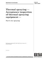
A typical stationary fuel cell power system is shown in Figure 1 .
EN 62282-3-1:2007
Power inputs
electrical thermal
Fuel
Oxidant
Ventilation
Inert gas
Water
EMS
Vibration,
wind, rain
temperature
etc.
–6–
Cabinet
or boundary
Fuel
processing
system
Oxidant
processing
system
Ventilation
system
Thermal
mangement
system
Recovered
heat
Waste heat
Fuel
cell
module
Power
conditioning
system
Water
treatment
system
Internal power
needs
Automatic
control
system
Onboard
energy
storage
Useable power
electrical
Discharge
water
Exhaust gases,
ventilation
EMI
Noise
vibration
IEC
4 33/07
Figure 1 – Stationary fu el cell power systems
The overall design of the power system anticipated by this standard shall form an assembly of
integrated systems, as necessary, intended to perform designated functions, as follows.
–
–
–
–
–
–
–
–
–
Fuel processing system: Catalytic or chemical processing equipment plus associated heat
exchangers and controls required to prepare the fuel for utilization within a fuel cell.
Oxidant processing system: The system that meters, conditions, processes and may
pressurize the incoming supply for use within the fuel cell power system.
Thermal management system: Provides cooling and heat rejection to maintain thermal
equilibrium within the fuel cell power system, and may provide for the recovery of excess
heat and assist in heating the power train during startup.
Water treatment system: Provides the treatment and purification of recovered or added
water for use within the fuel cell power systems.
Power conditioning system: Equipment which is used to adapt the electrical energy
produced to the requirements as specified by the manufacturer.
Automatic control system: The assembly of sensors, actuators, valves, switches and logic
components that maintains the fuel cell power system parameters within the
manufacturer’s specified limits without manual intervention.
Ventilation system: Provides, by mechanical means, air to a fuel cell power system’s
cabinet.
Fuel cell module: Assembly of one or more fuel cell stacks, electrical connections for the
power delivered by the stacks, and means for monitoring and/or control.
Fuel cell stack: Assembly of cells, separators, cooling plates, manifolds and a supporting
structure that electrochemically coverts, typically, hydrogen rich gas and air reactants to
d.c. power, heat, water and other byproducts.
–7–
EN 62282-3-1:2007
– Onboard energy storage: Internal energy source intended to aid or complement the fuel
cell module in providing power to internal or external loads.
This standard is applicable to stationary fuel cell power systems intended for indoor and
outdoor commercial, industrial and residential use in non-hazardous (unclassified) areas.
This standard contemplates all significant hazards, hazardous situations and events, with the
exception of those associated with environmental compatibility (installation conditions),
relevant to fuel cell power systems, when they are used as intended and under the conditions
foreseen by the manufacturer.
This standard deals with conditions that can yield hazards on the one hand to persons and on
the other to damage outside the fuel cell system only. Protection against damage to the fuel
cell system internals is not addressed in this standard, provided it does not lead to hazards
outside the fuel cell system.
The requirements of this standard are not intended to constrain innovation. When considering
fuels, materials, designs or constructions not specifically dealt with in this standard, these
alternatives shall be evaluated as to their ability to yield levels of safety and performance
equivalent to those prescribed by this standard.
2
Normative references
The following referenced documents are indispensable for the application of this document.
For dated references, only the edition cited applies. For undated references, the latest edition
of the referenced document (including any amendments) applies.
IEC 60079-0, Electrical apparatus for explosive gas atmospheres – Part 0: General
requirements
IEC 60079-2, Electrical apparatus for explosive gas atmospheres – Part 2: Pressurized
enclosures “p”
IEC 60079-1 0, Electrical apparatus for explosive gas atmospheres – Part 10: Classification of
hazardous areas
IEC 60079-1 6, Electrical apparatus for explosive gas atmospheres – Part 16: Artificial
ventilation for the protection of analyzer(s) houses
IEC 60079-20, Electrical apparatus for explosive gas atmospheres – Part 20: Data for
flammable gases and vapours, relating to the use of electrical apparatus
IEC 60204-1 , Safety of machinery – Electrical equipment of machines – Part 1: General
requirements
IEC 60300-3-9, Dependability management – Part 3: Application guide – Section 9: Risk
analysis of technological systems
IEC 60335-1 , Household and similar electrical appliances – Safety – Part 1: General
requirements
IEC 60335-2-51 , Household and similar electrical appliances – Safety – Part 2-51: Particular
requirements for stationary circulation pumps for heating and service water installations
IEC 60384-1 4, Fixed capacitors for use in electronic equipment – Part 14: Sectional
specification: Fixed capacitors for electromagnetic interference suppression and connection to
the supply mains
IEC 6041 7, Graphical symbols for use on equipment
EN 62282-3-1:2007
IEC 60529,
–8–
De gre es of p rote ction provide d by en closure s (IP Code )
IEC 60730-1 ,
A utoma tic e lectrica l con trols for h ouseh old a n d simila r use – Pa rt 1 : Gen e ra l
re quire me n ts
IEC 60730-2-5,
A utoma tic
e le ctrica l
con trols
for
h ouse h old
and
simila r
use
–
Pa rt
2-5:
use
–
Pa rt
2-6:
Pa rticula r re quire men ts for a utoma tic e lectrica l burn er con trol syste ms
IEC 60730-2-6,
Pa rticula r
A utoma tic
re quire me n ts
e le ctrica l
for
con trols
a utoma tic
for
h ouse h old
e le ctrica l
and
p re ssure
simila r
se n sin g
con trols
in cludin g
me ch a n ica l re quire me n ts
IEC 60730-2-9,
A utoma tic
e le ctrica l
con trols
for
h ouse h old
and
simila r
use
–
Pa rt
2-9:
Pa rticula r re quire me n ts for te mpera ture se n sin g con trols
IEC 60730-2-1 7,
Pa rticula r
A utoma tic
re quire men ts
e le ctrica l con trols
for
e lectrica lly
for h ouse h old a n d simila r use
ope ra te d
ga s
va lve s,
–
in cludin g
Pa rt 2-1 7:
me ch a n ica l
re quire me n ts
IEC 60730-2-1 9,
A utoma tic
e le ctrica l con trols
for h ouse h old a n d simila r use
–
Pa rt 2-1 9:
Pa rticula r re quire me n ts for e le ctrica lly opera ted oil va lves, in cludin g mech a n ica l require me n ts
IEC 6081 2,
A n a lysis tech n iques for syste m re lia b ility – Proce dure for fa ilure mode a n d e ffe cts
a n a lysis (FMEA )
IEC 60950-1 :2005,
IEC 61 000-3-2,
In forma tion te ch n ology e quipme n t – Sa fe ty – Pa rt 1 : Gen era l re quire me n ts
Ele ctroma gn e tic compa tibility (EMC) – Pa rt 3-2: L imits – L imits for h a rmon ic
curre n ts e mission s (equip me n t in put curre n t
IEC 61 000-3-3,
≤1 6
A p e r ph a se )
Ele ctroma gn e tic compa tibility (EMC) – Pa rt 3-3: L imits – L imita tion of volta ge
ch a n ge s, volta ge fluctua tion s a n d flicke r in public low-volta ge supp ly syste ms for e quip me n t
with ra ted curre n t
IEC 61 000-3-4,
≤1 6
A p er ph a se a n d n ot sub je ct to con ditiona l con n ection
Ele ctroma gn e tic
comp a tibility
(EMC)
–
Pa rt
3-4:
L imits
–
L imita tion
of
e mission of h a rmon ic curre n ts in low-volta ge powe r supp ly syste ms for e quipme n t with ra te d
curre n t gre a te r th a n 1 6 A
IEC 61 000-3-5,
ch a n ge s,
Ele ctroma gn e tic compa tibility (EMC) – Pa rt 3-5: L imits – L imita tion of volta ge
volta ge fluctua tion s a n d flicke r in low-volta ge supply syste ms for e quip me n t with
ra ted curre n t gre a te r th a n 1 6 A
IEC 61 000-6-1 ,
Ele ctroma gn e tic
compa tibility
(EMC)
–
Pa rt
6-1 :
Ge n e ric
sta n da rds
–
Immun ity for reside n tia l, comme rcia l a n d ligh t-in dustria l en viron men ts
IEC 61 000-6-2,
Ele ctroma gn e tic
compa tibility
(EMC)
–
Pa rt
6-2:
Ge n e ric
sta n da rds
–
(EMC)
–
Pa rt
6-3:
Ge n e ric
sta n da rds
–
sta n da rds
–
Immun ity for in dustria l en viron men ts
IEC 61 000-6-3,
Ele ctroma gn e tic
compa tibility
Emission sta n da rd for reside n tia l, comme rcia l a n d ligh t-in dustria l e n viron me n ts
IEC 61 000-6-4,
Ele ctroma gn e tic
compa tibility
(EMC)
–
Pa rt
6-4:
Ge n e ric
Emission sta n da rd for in dustria l e n viron men ts
IEC 61 025,
Fa ult tre e a n a lysis (FTA )
IEC 61 508 (all parts),
sa fe ty-re la te d syste ms
Fun ction a l
sa fe ty
of
e lectrica l/ele ctron ic/progra mma ble
e lectron ic
EN 62282-3-1:2007
–9–
IEC 61 51 1 -1 ,
Fun ction a l sa fe ty – Sa fe ty in strumen ted syste ms for th e proce ss in dustry sector
– Pa rt 1 : Fra me work, de fin ition s, syste m, h a rdwa re a n d softwa re re quireme n ts
IEC 61 51 1 -3,
Fun ction a l sa fe ty – Sa fe ty in strume n ted syste ms for th e proce ss in dustry sector
– Pa rt 3: Guida n ce for th e de te rmin a tion of th e require d sa fe ty in te grity leve ls
IEC 61 779-4,
Pa rt
4:
Electrica l a ppa ra tus for th e de te ction a n d me a sure men t of fla mma ble ga ses –
Performa n ce
re quire men ts
for
group
II
a pp a ra tus
in dica tin g
up
to
1 00%
lower
e xplosive lim it
IEC 61 779-6,
Pa rt
6:
Electrica l a ppa ra tus for th e de te ction a n d me a sure men t of fla mma ble ga ses –
Guide
for th e
se lection ,
in sta lla tion ,
use
and
ma in te n a n ce
of a ppa ra tus
for th e
de te ction a n d me a sure me n t of fla mma ble ga se s
IEC 61 882,
Ha za rd a n d ope ra bility studies (HA ZOP studie s) – A pp lica tion guide
IEC 62086-1 ,
Ele ctrica l a p pa ra tus for e xp losive ga s a tmosph e res – Ele ctrica l re sista n ce tra ce
h ea tin g – Pa rt 1 : Ge n e ra l a n d te stin g re quire me n ts
IEC 62282-2,
Fue l ce ll tech n ologie s – Pa rt 2: Fuel ce ll module s
IEC 62282-3-2,
Fue l
cell
te ch n ologie s
–
Pa rt
3-2:
Sta tion a ry
fue l
ce ll
powe r
syste ms
–
Performa n ce te st me th ods
IEC Guide 1 04:1 997,
Th e
pre pa ra tion
of sa fe ty publica tion s
a n d th e
use
of ba sic
sa fe ty
p ub lica tion s a n d group sa fe ty publica tion s
ISO 3864-2:2004,
Gra ph ica l symbols
–
Sa fe ty colours
a n d sa fe ty sign s
–
Pa rt 2:
De sign
p rin ciples for p roduct sa fe ty la be ls
ISO 441 3,
Hydra ulic fluid p ower – Gen era l rule s re la tin g to syste ms
ISO 441 4,
Pn euma tic fluid powe r – Ge n era l rule s re la tin g to syste ms
ISO 5388,
Sta tion a ry a ir compre ssors – Sa fe ty rule s a n d code of pra ctice
ISO 7000,
Gra ph ica l symb ols for use on e quip men t – In de x a n d syn opsis
ISO 1 0439,
Pe trole um, ch e mica l a n d ga s service in dustrie s – Ce n trifuga l compre ssors
ISO 1 0440-1 ,
Pe troleum
and
n a tura l
ga s
in dustries
–
Rota ry-type
positive-displa ce me n t
–
Rota ry-type
positive-displa ce me n t
compre ssors – Pa rt 1 : Proce ss compre ssors (oil-fre e )
ISO 1 0440-2,
Pe troleum
and
n a tura l
ga s
in dustries
compre ssors – Pa rt 2: Pa cka ge d a ir com pre ssors (oil-fre e )
ISO 1 0442,
Pe trole um,
ch e mica l a n d ga s se rvice in dustries – Pa cka ge d,
in te gra lly ge a re d
ce n trifuga l a ir com pre ssors
ISO 1 3631 ,
Pe troleum a n d n a tura l ga s in dustries – Pa cka ge d reciproca tin g ga s compressors
ISO 1 3707,
Pe troleum a n d n a tura l ga s in dustrie s – Reciproca tin g compressors
ISO 1 3709,
Ce n trifuga l p umps for pe troleum, pe troch e mica l a n d n a tura l ga s in dustrie s
ISO 1 3850,
Sa fety of ma ch in e ry – Eme rgen cy stop – Prin ciples for de sign
ISO 1 41 21 ,
Sa fe ty of ma ch in e ry – Prin cip le s of risk a ssessmen t
ISO 1 4847,
Rota ry positive displa ce me n t pumps – Te ch n ica l re quire me n ts
ISO 1 5649,
Pe troleum a n d n a tura l ga s in dustries – Pip in g
EN 62282-3-1:2007
ISO/TR 1 591 6,
– 10 –
Ba sic co n side ra tio n s fo r th e sa fe ty o f h ydro ge n syste ms
ISO/TS 1 6528,
Bo ile rs
and
p re ssure
ve sse ls
–
Re gistra tio n
of
co de s
and
sta n da rds
to
p ro m o te in te rn a tio n a l re co gn ition
ISO/IEC Guide 7:1 994,
G uide lin e s
fo r dra ftin g
o f sta n da rds
suita b le
fo r use
fo r co n form ity
a sse ssm e n t
ISO/IEC Guide 51 :1 999,
3
Sa fe ty a sp e cts – Guide lin e s fo r th e ir in clusio n in sta n da rds
Terms and definitions
For the purposes of this document, the following terms and definitions apply.
3.1
accessible
area to which, under normal operating conditions, one of the following applies:
a) access can be gained without the use of a tool;
b) the means of access is deliberately provided to the operator;
c) the operator is instructed to enter regardless of whether or not a tool is needed to gain
access
NOTE The terms "access" and "accessible", unless qualified, relate to operator access area as defined above.
3.2
circuit, extra low voltage (ELV)
secondary circuit with voltages between any two conductors of the circuit, and between any
one such conductor and earth not exceeding 42,4 V peak, or 60 V d.c., under normal
operating conditions, which is separated from hazardous voltage by basic insulation, and
which neither meets all of the requirements for an SELV circuit nor meets all of the
requirements for a limited current circuit
[IEC 60950]
3.3
circuit, limited current
circuit which is so designed and protected that, under both normal operating conditions and
single-fault conditions, the current which can be drawn is not hazardous
[IEC 60950]
3.4
circuit, primary
circuit which is directly connected to the a.c. mains supply. It includes, for example, the
means for connection to the a.c. mains supply, the primary windings of transformers, motors
and other loading devices
[IEC 60950]
3.5
circuit, safety-control
circuit or portion thereof involving one or more safety controls in which failure due to
grounding, opening or shorting of any part of the circuit can cause unsafe operation of the
controlled equipment
– 11 –
EN 62282-3-1:2007
3.6
circuit, safety extra low voltage (SELV)
secondary circuit which is so designed and protected that under normal operating conditions
and single-fault conditions, its voltages do not exceed a safe value
[IEC 60950]
3.7
circuit, secondary
circuit which has no direct connection to a primary circuit and derives its power from a
transformer, converter or equivalent isolation device, or from a battery
[IEC 60950]
3.8
circuit, telecommunications network voltage (TNV)
circuit which is in the equipment and to which the accessible area of contact is limited and
that is so designed and protected that, under normal operating conditions and single-fault
conditions, the voltages do not exceed specified limit values
[IEC 60950, 1 .2.8.8 for specific limits]
3.9
class I equipment
equipment where protection against electric shock is achieved by
a) using basic insulation;
b) providing a means of connection to the protective earthing conductor in the building wiring
to those conductive parts that are otherwise capable of assuming hazardous voltages if
the basic insulation fails
NOTE Class I equipment may have parts with double insulation or reinforced insulation.
3.1 0
design pressure
pressure used in the design of a component together with the coincident design material
temperature, for the purpose of determining the minimum permissible thickness or physical
characteristics
3.1 1
effluent
products of combustion plus the excess air being discharged from gas utilization equipment
(also see flue gases)
3.1 2
electrical equipment
see 3.1 4
3.1 3
ELV circuit
see 3.2
3.1 4
equipment, electrical
general term including material, fittings, devices appliances, fixtures, apparatus and the like
used as part of, or in connection with, and electrical installation
3.1 5
flame failure lock-out time
see 3.31
EN 62282-3-1:2007
– 12 –
3. 1 6
fu el cel l
electrochemical device that converts the chemical energy of a fuel, such as hydrogen or
hydrogen rich gases, alcohols, hydrocarbons and oxidants to DC power, heat and other
reaction products
3. 1 7
g as ven t
passageway, composed of listed factory-built components assembled in accordance with the
terms of listing, for conveying flue gases from gas utilization equipment or their vent
connectors to the outside atmosphere (see also 3.56)
3. 1 8
h eat exchan ger
vessel in which heat is transferred from one medium to another
3. 1 9
i gn iter
device which utilizes electrical energy to ignite gas at a pilot burner or main burner
3. 20
i g n i tion , au tom atic
ignition of gas at the burner when the gas controlling device is turned on, including re-ignition
if the flames on the burner have been extinguished by means other than by the closing of the
gas-controlling device
3. 21
i g n i tion devi ce
a) device for igniting gas at a burner. It may be a pilot or an igniter
b) d i rect ig n i tion
igniter utilized to ignite gas at a main burner
3. 22
i g n i tion system , au tomati c
system designed to ignite and reignite a main burner. Such systems
a) prove the presence of either the ignition source or main burner flame, or both;
b) automatically ignite gas at the main burner or at the pilot burner so that the pilot can ignite
the main burner;
c) automatically act to shut off the gas supply to the main burner or to the pilot burner and
main burner, when the supervised flame or ignition source is not proved
3. 23
i gn ition system ti m i n gs
a) flam e-establ i sh in g period
b)
c)
period of time between initiation of gas flow and proof of the supervised flame or between
the proof of supervised flame and initiation of gas flow. This may be applicable to proof of
the ignition source or main burner flame, or both;
i g n i tion activati on period
period of time between energizing the main gas valve and deactivation of the ignition
means prior to the lockout time;
l ockou t ti me
period of time between the initiation of gas flow and the action to shut off the gas flow in
the event of failure to establish proof of the supervised ignition source or the supervised
main burner flame. Reinitiating the lighting sequence requires a manual operation;
– 13 –
d)
m axim u m tim e
e)
pu rge ti m e
f)
recycl e ti me
EN 62282-3-1:2007
maximum allowable time for the specified function of any device;
period of time intended to allow for the dissipation of any unburned gas or residual
products of combustion
1 ) pre-pu rge tim e
purge time which occurs at the beginning of a burner operating cycle prior to initiating
ignition;
2) post-pu rge ti me
purge time which occurs at the end of a burner operating cycle;
period of time between shutoff of the gas supply following loss of the supervised ignition
source or the supervised main burner flame and reactivation of the ignition source
3. 24
i n su l ation
a) basic
b)
c)
d)
insulation to provide basic protection against electric shock
dou ble
insulation comprising both basic insulation and supplementary insulation
fu nctional
insulation that is necessary only for the correct functioning of the equipment
rein forced
single insulation system which provides a degree of protection against electric shock
equivalent to double insulation under the conditions specified in this standard
NOTE 1 Functional insulation by definition does not protect against electric shock. It may, however, reduce the
likelihood of ignition and fire.
NOTE 2 The term "insulation system" does not imply that the insulation should be in one homogenous piece. It
may comprise several layers which cannot be tested as supplementary insulation or basic installation.
3. 25
i n terl ock
control to prove the physical state of a required condition and to furnish that proof to the
safety shutoff device circuit
3. 26
j oi n ts
points of connection between heat transfer surfaces, between positive and negative pressure
zones within components of the fuel cell power system, and between fuel cell power system
components
3. 27
l abel led
equipment or materials to which has been attached a label, symbol or other identifying mark
of an organization acceptable to the authority having jurisdiction and concerned with product
evaluation that maintains periodic inspection of production of labelled equipment or materials
and by whose labelling the manufacturer indicates compliance with appropriate standards or
performance in a specified manner
3. 28
l i m i ted cu rrent ci rcu i t
see 3.3
EN 62282-3-1:2007
– 14 –
3. 29
l i sted
equipment or materials included in a list published by a nationally recognized testing
laboratory, inspection agency, or other organizations concerned with product evaluation that
maintains periodic inspection of production of listed equipment or materials, whose listing
states either that the equipment or material meets nationally recognized standards or has
been tested and found suitable for use in a specified manner
3. 30
l oad, n ormal
maximum load that is connected to the mains for systems that utilize an external mains power
source to idle, start, or maintain operation of the power system
3. 31
l ock-ou t tim e, fl am e fai l u re
period of time between the signal indicating absence of flame and lock-out
3. 32
m ai n bu rn er
device or group of devices essentially forming an integral unit for the final conveyance of gas
or a mixture of gas and air to the combustion zone, and on which combustion takes place to
accomplish the function for which the equipment is designed
3. 33
m an ifol d
conduit which supplies gas to or collects it from the fuel cell or the fuel cell stack
3. 34
m ateri al s
a) combu sti ble
when pertaining to materials adjacent to, or in contact with, heat-producing appliances,
vent connectors, gas vents, steam and hot water pipes, and warm air ducts, those
materials made of or surfaced with wood, compressed paper, plant fibres, or other
materials that are capable of being ignited and burned. Such materials shall be considered
combustible even though flame-proofed, fire-retardant treated, or plastered
b) n on -com bu sti ble
for the purposes of this standard, materials which are not capable of being ignited and
burned, such as materials consisting of, or a combination of, steel, iron, brick, tile,
concrete, slate, asbestos, glass and plaster
3. 35
m axi m u m al l owabl e workin g pressu re
see 3.63
3. 36
m axi m u m operatin g pressu re
see 3.39
3. 37
n orm al load
see 3.30
3. 38
n orm al operati n g condi ti ons
operation of the fuel cell power system under normal conditions, in particular:
– 15 –
EN 62282-3-1:2007
– nominal (rated) power output with respect to voltage and current;
– nominal thermal energy output with respect to temperature and cooling media flow (if
applicable);
– nominal temperature range of the all subsystems of the fuel cell power system;
– nominal fuel composition;
– nominal flows of anode and cathode media;
– nominal pressure ranges in all fluids within the power system;
– change of power output (electrical and thermal) within the nominal ranges defined in the
manufacturer’s specification;
unless otherwise stated, the entire fuel cell system is operated within 2 % of the rated input
voltage and frequency and within 5 % of the rated fuel consumption when operated at rated
output conditions, as specified by the manufacturer. Tolerances for the other values should be
specified by the manufacturer
NOTE Deviations from these nominal operating conditions are defined as abnormal operating conditions.
3.39
operating pressure, maximum (MOP)
highest gauge pressure of a component or system that is expected during normal operation
including starts, stops and transients
3.40
passive state
state for the fuel cell power system internal components normally entered when the fuel cell
power system is purged with steam, air or nitrogen, or according to the manufacturer's
instructions when the fuel cell power system is turned off, or prior to when the fuel cell power
system is turned on (initialization)
3.41
pilot
small gas flame used to ignite the gas at the main burner
a) continuous
pilot that burns without turndown throughout the entire time the burner is in service,
whether the main burner is firing or not;
b) expanding
continuous pilot that is automatically expanded so as to reliably ignite the main burner.
This pilot may be turned down at the end of the main burner flame-establishing period;
c) intermittent
pilot which is automatically lighted each time there is a signal for initialization. It burns
during the entire period that the main burner is firing;
d) interrupted
pilot which is automatically lighted each time there is a signal for initialization. The pilot
fuel is cut off automatically at the end of the main burner flame-establishing period;
e) proved
a pilot flame supervised by a primary safety control
3.42
piping system
all piping, valves and fittings used to connect gas utilization equipment to the point of delivery
EN 62282-3-1:2007
– 16 –
3.43
pluggable equipment type A
e q u i p m e n t wh i ch i s i n te n d e d fo r co n n e cti o n to th e b u i l d i n g i n s ta l l a ti o n wi ri n g vi a a n o n i n d u s tri a l p l u g a n d so cke t-o u tl e t o r a n o n -i n d u s tri a l a pp l i a n ce cou p l e r, o r b o th
3.44
port
a n y o p e n i n g i n a b u rn e r h e a d th ro u g h wh i ch g a s o r g a s- a i r m i xtu re i s d i sch a rg e d fo r i g n i ti on
3.45
power system
p a cka g e d ,
s e l f-co n ta i n e d ,
a u tom a ti ca l l y
op e ra te d
assembl y
of
i n te g ra te d
s ys te m s
fo r
g e n e ra ti n g u se fu l e l e ctri ca l e n e rg y a n d re co ve ra b l e th e rm a l e n e rg y
3.46
primary circuit
see 3. 4
3.47
purge
fre e i n g a g a s co n d u i t o f a i r, g a s o r a m i xtu re o f a i r a n d g a s
3.48
reformer
ve s s e l wi th i n wh i ch fu e l g a s a n d o th e r g a s e o u s re cycl e s tre a m (s ) ( i f p re s e n t) a re re a cte d wi th
wa te r va p ou r a n d h e a t, u s u a l l y i n th e p re s e n ce o f a ca ta l ys t, to p ro d u ce h yd ro g e n ri ch g a s fo r
u s e wi th i n th e fu e l ce l l p o we r s ys te m
3.49
regulator, draft
d e vi ce wh i ch fu n cti o n s to m a i n ta i n a d e s i re d d ra ft i n th e e q u i p m e n t b y a u to m a ti ca l l y re d u ci n g
th e d ra ft to th e d e s i re d va l u e
3.50
secondary circuit
see 3. 7
3.51
SELV circuit
see 3. 6
3.52
specific gravity
ra ti o o f th e we i g h t or m a ss o f a g i ve n vol u m e of a s u b s ta n ce to th a t o f a n e q u a l vo l u m e o f
a n o th e r s u b s ta n ce ( a i r fo r g a s e s , wa te r fo r l i q u i d s a n d so l i d s ) u se d a s a s ta n d a rd , b o th
m e a s u re d u n d e r th e s a m e co n d i ti on s
3.53
stop
fi xe d po i n t on a con tro l , s u ch a s a te m p e ra tu re l i m i t con tro l , wh i ch p re ve n ts th e a d j u s tm e n t o f
th e con tro l b e yo n d th e s to p po i n t
3.54
thermal equilibrium conditions
s ta b l e te m p e ra tu re co n d i ti o n s i n d i ca te d b y te m p e ra tu re ch a n g e s o f n o m o re th a n 3 K (5 o F ) or
1 % o f th e a b s o l u te op e ra ti n g te m p e ra tu re , wh i ch e ve r i s h i g h e r b e twe e n two re a d i n g s 1 5 m i n
a pa rt
3.55
TNV circuit
see 3. 8
– 17 –
EN 62282-3-1:2007
3.56
vent
passageway or conduit for conveying products of combustion from gas utilization equipment,
or their vent connectors, to the outside atmosphere
3.57
vent connector
that portion of the venting system which connects the flue outlet of gas utilization equipment
to the gas vent or single-wall metal pipe
3.58
vent gases
products of combustion from gas utilization equipment plus excess air, plus dilution air in the
venting system above the draft regulator or similar device
3.59
vent terminal (vent cap)
fitting at the end of the vent pipe that directs the flue products into the outside atmosphere
3.60
ventilation
natural or mechanical process of supplying conditioned or unconditioned air to, or removing
such air from, any space
3.61
venting system
gas vent or single-wall metal pipe, and vent connector if used, assembled to form a
continuous open passageway from the flue collar of gas utilization equipment to the outside
atmosphere for the purpose of removing vent gases
3.62
voltage, hazardous
voltage exceeding 42,4 V peak or 60 V d.c. existing in a circuit which does not meet the
requirements for either a limited current circuit or a TNV circuit
[IEC 60950]
3.63
working pressure, maximum allowable (MAWP)
highest gauge pressure of the working fluid (gas or liquid) to which the process equipment or
system is rated with consideration for initiating fault management above normal operation
NOTE A margin is usually provided between the MOP and set-points of pressure relief devices which are set at,
or below, the MAWP.
4 Safety requirements and protective measures
4.1 General safety strategy
The manufacturer shall ensure that
– all foreseeable hazards, hazardous situations and events associated with the fuel cell
power systems throughout their anticipated lifetime have been identified;
– the risk for each of these hazards has been estimated from the combination of probability
of occurrence of the hazard and of its foreseeable severity according to ISO 1 41 21 ,
IEC 61 882, IEC 60300-3-9, or IEC 61 51 1 -3 as applicable, or equivalent;
EN 62282-3-1:2007
– 18 –
– the two factors which determine each one of the estimated risks (probability and severity)
have been eliminated or reduced as far as possible during the design including reasonably
foreseeable misuse (inherently safe design and construction);
– the necessary protection measures in relation to risks that are not or cannot be eliminated
have been taken (provision of warning and safety devices);
– users are informed of any additional safety measures that they may be required to
implement.
Based on the quantity of fuel and other stored energy (for example, flammable materials,
pressurized media, electrical energy, mechanical energy, etc.) in the fuel cell systems, there
is a need to eliminate potential hazards. The general safety strategy for the fuel cell systems
shall be established according to the following sequence:
– eliminate hazards to outside the fuel cell system, when such energy is released nearly
instantaneously; or
– passively control (for example, burst disks, release valves, thermal cut-off devices) such
forms of energy to ensure a release without endangering the ambient; or
– actively control such forms of energy (for example, by electronic control equipment
included in the fuel cell system, which enforces adequate countermeasures based on the
evaluation of sensor signals). In this case, the remaining risk due to failures in such
control equipment shall be investigated in detail. Guidance for safety critical components
can be found in IEC 61 508; or
– provide appropriate safety markings, concerning the remaining risks of hazards.
Using the techniques described above, special care shall be taken to address the hazards
listed in Annex A.
4.1 .2
The manufacturer shall demonstrate that the necessary protection measures in
relation to risks that are not eliminated have been taken by performing a safety and reliability
analysis which is intended to identify failures that have significant consequences affecting the
safety of the system.
The reliability analysis shall be performed in accordance with IEC 6081 2, IEC 61 025, or
equivalent.
4.1 .3 Behaviour at normal and abnormal operating conditions
The fuel cell system shall be manufactured in such a way that it withstands all normal
operating conditions as defined by the manufacturer’s specification without any damage. In
case of foreseeable abnormal operating conditions, the fuel cell system shall be manufactured
and designed taking into consideration 4.1 .
4.2 Physical environment and operating conditions
4.2.1 General
The fuel cell power system and protective systems shall be so designed and constructed as to
be capable of performing their intended function in the physical environment and operating
conditions specified in 4.2.2 to 4.2.8.
– 19 –
4.2.2
Electrical power input
4.2.3
Physical environment
EN 62282-3-1:2007
The fuel cell power system shall be designed to operate correctly with the conditions of
electrical power input specified in IEC 60204-1 or as otherwise specified by the manufacturer.
The manufacturer shall specify the physical environment conditions for which the fuel cell
power system is suitable. Consideration should be given to
– indoor/outdoor use;
– the altitude above sea-level up to which the fuel cell power system shall be capable of
operating correctly;
– the range of air temperatures and humidity within which the fuel cell power system shall
be capable of operating correctly;
– the seismic zone where it may be sited.
4.2.4
Fuel input
4.2.5
Water input
4.2.6
Vibration, shock and bu mp
4.2.7
H andling, transportation, and storage
The fuel cell power system should be designed to operate correctly with the composition limits
and supply characteristics of the fuels for which its design is intended (for example, pipeline
natural gas). In the user’s manual, the manufacturer shall specify the composition limits and
supply characteristics of the fuels to be used in the fuel cell power system.
The quality and supply characteristics of the water to be used in the fuel cell power systems
shall be specified by the manufacturer.
The undesirable effects of vibration, shock and bump (including those generated by the
machine and its associated equipment and those created by the physical environment) shall
be avoided by the selection of suitable equipment, by mounting it away from the fuel cell
power system, or by the use of anti-vibration mountings. This does not include the effects of
seismic shock, which shall be addressed separately if the manufacturer deems it appropriate
for its product (see 4.2.3).
The fuel cell power system shall be designed to withstand, or suitable precautions shall be
taken to protect against, the effects of transportation and storage temperatures within a range
of –25 ° C to +55 ° C and for short periods not exceeding 24 h at up to +70 ° C. Alternative
temperature ranges may be specified by the manufacturer.
The fuel cell power system or each component part thereof shall
– be capable of being handled and transported safely, when necessary, be provided with
suitable means for handling by cranes or similar equipment;
– be packaged or designed so that it can be stored safely and without damage (for example,
adequate stability, special supports, etc.).
The manufacturer shall specify special means for handling, transportation and storage if
required.
EN 62282-3-1:2007
4.2.8
– 20 –
System purging
Means shall be provided in fuel cell systems to purge where for safety reasons a passive
state is required after shutdown or prior to startup, as specified by the manufacturer. A
suitable purge system utilizing a medium specified by the manufacturer such as, but not
limited to, nitrogen, air or steam in a non-hazardous situation within the intended use may be
used.
4.3
Selection of materials
All materials shall be suitable for the intended purpose.
4.3.1
When materials used to construct the fuel cell power system are known to pose
hazards under certain circumstances, the manufacturer shall implement the measures and
provide the information necessary to sufficiently minimize the risk of endangering persons’
safety or health.
4.3.2
Asbestos or asbestos-containing material(s) shall not be used in the construction
of a fuel cell power system.
4.3.3
Metallic and non-metallic materials used to construct internal or external parts of
the fuel cell power system, in particular those exposed directly or indirectly to moisture or that
contain process gas or liquid streams as well as all parts and materials used to seal or
interconnect the same, for example, welding consumables, shall be suitable for all physical,
chemical and thermal conditions which are reasonably foreseeable within the scheduled
lifetime of the equipment and for all test conditions; in particular,
– they shall retain their mechanical stability with respect to strength (fatigue properties,
endurance limit, creep strength) when exposed to the full range of service conditions and
lifetime as specified by the manufacturer;
– they shall be sufficiently resistant to the chemical and physical action of the fluids that
they contain and to environmental degradation; the chemical and physical properties
necessary for operational safety shall not be significantly affected within the scheduled
lifetime of the equipment unless replacement is foreseen; specifically, when selecting
materials and manufacturing methods, due account shall be taken of the material’s
corrosion and wear resistance, electrical conductivity, impact strength, aging resistance,
the effects of temperature variations, the effects arising when materials are put together
(for example, galvanic corrosion), the effects of ultraviolet radiation, and to the
degradation effects of hydrogen on the mechanical performance of a material. Guidance to
account for the degradation effects of hydrogen on the mechanical performance of a
material can be found in ISO/TR 1 591 6 and Annex B.
4.3.4
Where conditions of erosion, abrasion, corrosion or other chemical attack may
arise, adequate measures shall be taken to
– minimize that effect by appropriate design, for example, additional thickness, or by
appropriate protection, for example, use of liners, cladding materials or surface coatings,
taking due account of the intended and reasonably foreseeable use;
– permit replacement of parts which are most affected;
– draw attention, in the instructions referred to in 7.4.5, to the type and frequency of
inspection and maintenance measures necessary for continued safe use; where
appropriate, it shall be indicated which parts are subject to wear and the criteria for
replacement.
EN 62282-3-1:2007
– 21 –
4.4 General requirements
4.4.1
In so far as their purpose allows, accessible parts of the fuel cell power system
shall have no sharp edges, no sharp angles, and no rough surfaces likely to cause injury.
The fuel cell power system or parts of it where persons are liable to move about or
stand shall be designed and constructed to prevent persons slipping, tripping or falling on or
off these parts.
4.4.2
4.4.3
The fuel cell power system, components and fittings thereof shall be so designed
and constructed that they are stable enough, under the foreseen operating conditions (if
necessary taking climatic conditions into account) for use without risk of overturning, falling or
unexpected movement. Otherwise, appropriate means of anchorage shall be incorporated and
indicated in the instructions.
The moving parts of the fuel cell power system shall be designed, built and laid out
to avoid hazards or, where hazards persist, fixed with guards or protective devices in such a
way as to prevent all risk of contact which could lead to accidents.
4.4.4
The various parts of the fuel cell power system and their linkages shall be so
constructed that, when used normally, no instability, distortion, breakage or wear likely to
impair their safety can occur.
4.4.5
The fuel cell power system shall be so designed, constructed and/or equipped that
risks due to gases, liquids, dust, or vapors released during the operation or maintenance of a
fuel cell power system, or used in its construction can be avoided.
4.4.6
4.4.7
All parts shall be securely mounted or attached and rigidly supported. The use of
shock-mounts is permitted when suitable for the application.
All safety shutdown system components whose failure may result in a hazardous
event, as identified by the reliability/safety analysis noted in 4.9.1 , shall be recognized,
certified or separately tested for their intended usage.
4.4.8
4.4.9
Risk of injury caused by contact with, or proximity to, external surfaces of the
appliance enclosure, handles, grips, or knobs at high temperatures.
a) The manufacturer shall take steps to eliminate any risk of injury caused by contact with, or
proximity to, external surfaces of the fuel cell power system enclosure, handle, grips, or
knobs at high temperatures.
If external surfaces of the fuel cell power system’s enclosure, handles, grips, knobs, or
similar parts may be contacted by users without personal protective equipment while the
fuel cell system is in operation, the manufacturer shall either limit the temperature of these
surfaces according to Table 1 or the manufacturer shall fix guards or protective devices in
such a way as to prevent risk of contact that could lead to accidents.
Table 1 – Allowable surface temperatures
Part
Tem peratu re ri se
C
60
°
External enclosures, except handles held in
normal use
Surfaces of handles, knobs, grips and similar
parts which are held for short periods only in
normal use
- of metal
- of porcelain
- of moulded material (plastic), rubber or wood
35
45
60
EN 62282-3-1:2007
– 22 –
Maximum surface temperature rises above ambient of external surfaces that may be
contacted during operation by people without personal protective equipment. The above
values are referenced in Table 3 of IEC 60335-1 .
b) The temperatures on walls, o floor and ceiling adjacent to a stationary fuel cell power
system shall not exceed 50 C above ambient temperature under the test conditions of
5.1 3b).
4.4.1 0
The fuel cell power system shall be so designed and constructed that the emission
of airborne noise is reduced to a level suited for the intended use or location in compliance
with applicable regional or national airborne noise codes and standards.
The fuel cell power system exhaust to atmosphere, under normal steady-state
operating conditions, shall not contain concentrations of carbon monoxide in excess of
300 ppm in an air-free sample of the effluents, which is a sample that has its effluent CO
concentration mathematically corrected as though there was zero per cent excess air.
4.4.1 1
4.4.1 2
Where explosive, flammable, or toxic fluids are contained in the piping, appropriate
precautions shall be taken in the design and marking of sampling and take-off points.
4.4.1 3
The maximum temperatures of components and materials, as installed in the fuel
cell power system, shall not exceed their temperature ratings.
4.4.1 4
The manufacturer shall give consideration to the suitability of the fuel cell power
system to operate where contaminants (for example, dust, salt, smoke, and corrosive gases)
are present in the physical environment.
The fuel cell power system enclosure shall be designed to safely contain any
anticipated hazardous liquid leaks (see 4.5.2f) for liquid fuel). The containment means shall
have a capacity of 1 1 0 % of the maximum volume of fluid anticipated to leak.
4.4.1 5
4.5 Pressure equipment and piping
4.5.1
Pressure equipment
Pressurized vessels, such as reactors, heat exchangers, gas-fired tube heaters and boilers,
electric boilers, coolers, accumulators and similar containers, and associated pressure relief
mechanisms, such as relief valves and similar devices, shall be constructed and marked in
accordance with applicable regional or national pressure equipment codes and standards.
ISO 1 6528 provides information concerning pressure equipment standards.
Vessels that, in accordance with the applicable regional or national pressure equipment codes
and standards, do not qualify as “pressure vessels”, such as tanks and similar containers,
shall be constructed of suitable materials in accordance with 4.3 and shall meet the applicable
requirements of 4.4. Such vessels, and their related joints and fittings, shall be designed and
constructed with adequate strength for functionality and leakage resistance to prevent
unintended releases.
4.5.2
Piping systems
Piping and its associated joints and fittings shall conform to the applicable sections of
ISO 1 5649.
– 23 –
EN 62282-3-1:2007
Piping systems designed for internal gauge pressure at or above zero but less than 1 05 kPa,
handling fluids that are non-flammable, non-toxic and not damaging to human tissue and
having a design temperature from − 29 °C through 1 86 °C are not included in the scope of
ISO 1 5649. Piping systems under these conditions shall be constructed of suitable materials
in accordance with 4.3 and shall meet the applicable requirements of 4.4. Such pipes, and
their related joints and fittings, shall be designed and constructed with adequate strength for
functionality and leakage resistance to prevent unintended releases.
The design and construction of both rigid and flexible pipes and fittings shall consider the
following aspects.
a) Materials shall meet the requirements specified in 4.3.
b) The internal surfaces of piping shall be thoroughly cleaned to remove loose particles, and
the ends of piping shall be carefully reamed to remove obstructions and burrs.
c) If fluid condensate or sediment accumulation inside gaseous fluid piping could cause
damage from water hammer, vacuum collapse, corrosion and uncontrolled chemical
reactions during startup, shutdown and/or use, the manufacturer shall provide means for
drainage and removal of deposits from low areas and for access during cleaning,
inspection and maintenance. In particular, the manufacturer shall take measures to ensure
against sediment or condensate accumulation in fuel gas controls. Sediment traps or
filters shall be installed or adequate guidelines shall be provided in the product’s technical
documentation.
d) The manufacturer shall take measures to ensure against sediment accumulation in liquid
fuel controls. Sediment traps or filters shall be installed or adequate guidelines shall be
provided in the technical documentation of the product.
e) Non-metallic piping used to convey combustible gases shall be protected against the
possibility of overheating. Measures as required by the safety and reliability analysis
specified in 4.1 .2 shall be provided to prevent the temperature of components conveying
combustible gases from surpassing their design temperatures.
f) Liquid fuel cell power systems shall include provisions for capturing, recycling, or safe
disposal of released liquid fuel. Drip pans, spill guards, or double-walled pipe shall be
designed to prevent uncontrolled releases.
4. 5.3
Flue gas venting systems
The fuel cell power system shall be provided with a vent system to convey products of
combustion from fuel utilization equipment to the outside atmosphere. This requirement may
be exempted by installation standards for small (less than 1 0 kW net electrical output) fuel
cell power systems. The manufacturer shall design and construct the vent pipe, or provide in
the product’s technical documentation instructions to design and construct the vent pipe, in
compliance with the following requirements.
a) Materials shall meet the requirements specified in 4.3. In particular, the venting system
shall be constructed of material resistant to corrosion by condensate. Non-metallic
material shall be judged on its temperature limitation, strength and resistance to the action
of condensate.
b) The venting system parts of a fuel cell power system shall be durable. Venting system
parts, including parts within the fuel cell power system, shall not break, disassemble or
become damaged to the extent that they permit unsafe fuel cell power system operation.