Bsi bs en 62056 6 2 2016
Bạn đang xem bản rút gọn của tài liệu. Xem và tải ngay bản đầy đủ của tài liệu tại đây (12.16 MB, 316 trang )
BS EN 62056-6-2:2016
BSI Standards Publication
Electricity metering data exchange The DLMS/COSEM suite
Part 6-2: COSEM interface classes
BRITISH STANDARD
BS EN 62056-6-2:2016
National foreword
This British Standard is the UK implementation of EN 62056-6-2:2016. It is
identical to IEC 62056-6-2:2016. It supersedes BS EN 62056-6-2:2013 which
is withdrawn.
The UK participation in its preparation was entrusted to Technical
Committee PEL/13, Electricity Meters.
A list of organizations represented on this committee can be obtained on
request to its secretary.
This publication does not purport to include all the necessary provisions of
a contract. Users are responsible for its correct application.
© The British Standards Institution 2017.
Published by BSI Standards Limited 2017
ISBN 978 0 580 86671 5
ICS 17.220.01; 35.110; 91.140.50
Compliance with a British Standard cannot confer immunity from
legal obligations.
This British Standard was published under the authority of the
Standards Policy and Strategy Committee on 31 January 2017.
Amendments/corrigenda issued since publication
Date
Text affected
BS EN 62056-6-2:2016
EUROPEAN STANDARD
EN 62056-6-2
NORME EUROPÉENNE
EUROPÄISCHE NORM
December 2016
ICS 17.220; 35.110; 91.140.50
Supersedes EN 62056-6-2:2013
English Version
Electricity metering data exchange - The DLMS/COSEM suite Part 6-2: COSEM interface classes
(IEC 62056-6-2:2016)
Échange des données de comptage de l'électricité La suite DLMS/COSEM - Partie 6-2: Classes d'interfaces
COSEM
(IEC 62056-6-2:2016)
Datenkommunikation der elektrischen Energiemessung DLMS/COSEM - Teil 6-2: COSEM Interface-Klassen
(IEC 62056-6-2:2016)
This European Standard was approved by CENELEC on 2016-03-29. CENELEC members are bound to comply with the CEN/CENELEC
Internal Regulations which stipulate the conditions for giving this European Standard the status of a national standard without any alteration.
Up-to-date lists and bibliographical references concerning such national standards may be obtained on application to the CEN-CENELEC
Management Centre or to any CENELEC member.
This European Standard exists in three official versions (English, French, German). A version in any other language made by translation
under the responsibility of a CENELEC member into its own language and notified to the CEN-CENELEC Management Centre has the
same status as the official versions.
CENELEC members are the national electrotechnical committees of Austria, Belgium, Bulgaria, Croatia, Cyprus, the Czech Republic,
Denmark, Estonia, Finland, Former Yugoslav Republic of Macedonia, France, Germany, Greece, Hungary, Iceland, Ireland, Italy, Latvia,
Lithuania, Luxembourg, Malta, the Netherlands, Norway, Poland, Portugal, Romania, Slovakia, Slovenia, Spain, Sweden, Switzerland,
Turkey and the United Kingdom.
European Committee for Electrotechnical Standardization
Comité Européen de Normalisation Electrotechnique
Europäisches Komitee für Elektrotechnische Normung
CEN-CENELEC Management Centre: Avenue Marnix 17, B-1000 Brussels
© 2016 CENELEC All rights of exploitation in any form and by any means reserved worldwide for CENELEC Members.
Ref. No. EN 62056-6-2:2016 E
BS EN 62056-6-2:2016
EN 62056-6-2:2016
European foreword
The text of document 13/1651A/FDIS, future edition 2 of IEC 62056-6-2, prepared by
IEC/TC 13 "Electrical energy measurement and control" was submitted to the IEC-CENELEC parallel
vote and approved by CENELEC as EN 62056-6-2:2016.
The following dates are fixed:
•
latest date by which the document has to be
implemented at national level by
publication of an identical national
standard or by endorsement
(dop)
2017-06-09
•
latest date by which the national
standards conflicting with the
document have to be withdrawn
(dow)
2019-12-09
This document supersedes EN 62056-6-2:2013.
Attention is drawn to the possibility that some of the elements of this document may be the subject of
patent rights. CENELEC [and/or CEN] shall not be held responsible for identifying any or all such
patent rights.
This document has been prepared under a mandate given to CENELEC by the European Commission
and the European Free Trade Association.
Endorsement notice
The text of the International Standard IEC 62056-6-2:2016 was approved by CENELEC as a
European Standard without any modification.
In the official version, for Bibliography, the following notes have to be added for the standards indicated:
2
IEC 62056-4-7:2015
NOTE
Harmonized as EN 62056-4-7:2015 (not modified).
IEC 62056-7-6:2013
NOTE
Harmonized as EN 62056-7-6:2013 (not modified).
IEC 62056-8-3:2013
NOTE
Harmonized as EN 62056-8-3:2013 (not modified).
IEC 62056-9-7:2013
NOTE
Harmonized as EN 62056-9-7:2013 (not modified).
BS EN 62056-6-2:2016
EN 62056-6-2:2016
Annex ZA
(normative)
Normative references to international publications
with their corresponding European publications
The following documents, in whole or in part, are normatively referenced in this document and are
indispensable for its application. For dated references, only the edition cited applies. For undated
references, the latest edition of the referenced document (including any amendments) applies.
NOTE 1 When an International Publication has been modified by common modifications, indicated by (mod), the relevant
EN/HD applies.
NOTE 2 Up-to-date information on the latest versions of the European Standards listed in this annex is available here:
www.cenelec.eu
Publication
Year
Title
EN/HD
Year
-
-
Communication systems for meters and
remote reading of meters Part 2: Physical and link layer
EN 13757-2
2004
-
-
Communication systems for meters and
remote reading of meters Part 3: Dedicated application layer
EN 13757-3
2004
-
-
Communication systems for meters and
remote reading of meters Part 3: Dedicated application layer
EN 13757-3
2013
-
-
Communication systems for meters Part 5: Wireless M-Bus relaying
EN 13757-5
2015
IEC 61334-4-32
1996
Distribution automation using distribution
line carrier systems Part 4: Data communication protocols Section 32: Data link layer - Logical link
control (LLC)
EN 61334-4-32
1996
IEC 61334-4-41
1996
Distribution automation using distribution
line carrier systems Part 4: Data communication protocols Section 41: Application protocols Distribution line message specification
EN 61334-4-41
1996
IEC 61334-4-511
2000
Distribution automation using distribution EN 61334-4-511
line carrier systems Part 4-511: Data communication protocols
- Systems management - CIASE protocol
2000
IEC 61334-4-512
2001
Distribution automation using distribution EN 61334-4-512
line carrier systems Part 4-512: Data communication protocols
- System management using
profile 61334-5-1 - Management
Information Base (MIB)
2002
IEC 61334-5-1
2001
Distribution automation using distribution EN 61334-5-1
line carrier systems Part 5-1: Lower layer profiles - The spread
frequency shift keying (S-FSK) profile
2001
1)
1)
Superseded by EN 13757-3:2013.
3
BS EN 62056-6-2:2016
EN 62056-6-2:2016
Publication
Year
Title
EN/HD
Year
IEC 61334-6
2000
Distribution automation using distribution
line carrier systems Part 6: A-XDR encoding rule
EN 61334-6
2000
IEC 62056-21
2002
Electricity metering - Data exchange for
meter reading, tariff and load control Part 21: Direct local data exchange
EN 62056-21
2002
IEC 62056-31
1999
Electricity metering - Data exchange for
meter reading, tariff and load control Part 31: Use of local area networks on
twisted pair with carrier signalling
EN 62056-31
2000
IEC 62056-3-1
2013
Electricity metering data exchange - The
DLMS/COSEM suite Part 3-1: Use of local area networks on
twisted pair with carrier signalling
EN 62056-3-1
2014
IEC 62056-46
+ A1
2002
2006
Electricity metering - Data exchange for
meter reading, tariff and load control Part 46: Data link layer using HDLC
protocol
EN 62056-46
+ A1
2002
2007
IEC 62056-5-3
2016
Electricity metering data exchange - The EN 62056-5-3
DLMS/COSEM suite Part 5-3: DLMS/COSEM application layer
2016
IEC 62056-6-1
2015
Electricity metering data exchange - The
DLMS/COSEM suite Part 6-1: Object Identification System
(OBIS)
EN 62056-6-1
2016
ISO/IEC 8802-2
1998
Information technology Telecommunications and information
exchange between systems - Local and
metropolitan area networks - Specific
requirements Part-2: Logical link control
-
-
ISO/IEC/IEEE
60559
2011
Information technology - Microprocessor
Systems - Floating-Point arithmetic
-
-
IEEE 802.15.4
2006
IEEE Standard for Information technology- Telecommunications and information
exchange between systems- Local and
metropolitan area networks- Specific
requirements
Part 15.4: Wireless Medium Access
Control (MAC) and Physical Layer (PHY)
Specifications for Low-Rate Wireless
Personal Area Networks (WPANs)
-
ITU-T G.9901
2014
SERIES G: TRANSMISSION SYSTEMS AND MEDIA, DIGITAL SYSTEMS AND
NETWORKS - Access Networks - In
premises networks - Narrow-band
orthogonal frequency division multiplexing
power line communication transceivers Power spectral density specification
-
2)
4
Superseded by EN 62056-3-1:2014 (IEC 62056-3-1:2013).
2)
BS EN 62056-6-2:2016
EN 62056-6-2:2016
Publication
Year
Title
EN/HD
Year
ITU-T
G.9903:2012/A1
2013
-
ITU-T G.9903
2014
SERIES G: TRANSMISSION SYSTEMS AND MEDIA, DIGITAL SYSTEMS AND
NETWORKS - Access networks - In
premises networks – Narrow-band
orthogonal frequency division multiplexing
power line communication transceivers for
G3-PLC networks
SERIES G: TRANSMISSION SYSTEMS AND MEDIA, DIGITAL SYSTEMS AND
NETWORKS - Access networks - In
premises networks - Narrow-band
orthogonal frequency division multiplexing
power line communication transceivers for
G3-PLC networks
ITU-T G.9904
2012
SERIES G: TRANSMISSION SYSTEMS AND MEDIA, DIGITAL SYSTEMS AND
NETWORKS - Access networks - In
premises networks - Narrow-band
orthogonal frequency division multiplexing
power line communication transceivers for
PRIME networks
-
ETSI GSM 05.08
-
Digital cellular telecommunications system (Phase 2+); Radio subsystem link control
-
ANSI C12.19/
IEEE 1377
1997
1997
Utility Industry End Device Data Tables
-
-
IETF STD 51
1994
The Point-to-Point Protocol (PPP)
-
-
IETF RFC 791
1981
INTERNET PROTOCOL DARPA
INTERNET PROGRAM PROTOCOL
SPECIFICATION
-
-
IETF RFC 1332
1992
The PPP Internet Protocol Control Protocol (IPCP)
-
IETF RFC 1570
1994
PPP LCP Extensions
-
-
IETF RFC 1661
1994
Point-to-Point Protocol (PPP)
-
-
IETF RFC 1662
1994
PPP in HDLC-like Framing
-
-
RFC 1994
1996
PPP Challenge Handshake Authentication Protocol (CHAP)
-
RFC 2433
1998
PPP CHAP Extension
-
-
IETF RFC 2474
1998
Definition of the Differentiated Services
Field (DS Field) in the IPv4 and IPv6
Headers
-
-
IETF RFC 2507
1999
IP Header Compression
-
-
RFC 2759
2000
Microsoft PPP CHAP Extensions
-
-
IETF RFC 3241
2002
Robust Header Compression (ROHC) over PPP
-
RFC 3513
2003
Internet Protocol Version 6 (IPv6)
Addressing Architecture
-
-
RFC 3544
IETF RFC 4861
2003
2007
IP Header Compression over PPP
Neighbor Discovery for IP version 6 (IPv6) -
-
-
Point-to-Point (PPP) Protocol Field Assignments. Online database. Available from:
/>
5
BS EN 62056-6-2:2016
EN 62056-6-2:2016
6
–2–
BS EN 62056-6-2:2016
IEC 62056-6-2:2016 © IEC 2016
CONTENTS
FOREWORD ......................................................................................................................... 9
INTRODUCTION ................................................................................................................. 12
1
Scope .......................................................................................................................... 14
2
Normative references................................................................................................... 14
3
Terms, definitions and abbreviations ............................................................................ 16
3.1
3.2
3.3
Terms and definitions related to the Image transfer process (see 5.3.6) ............... 16
Terms and definitions related to the S-FSK PLC setup classes (see 5.8) .............. 17
Terms and definitions related to the PRIME NB OFDM PLC setup ICs
(see 5.10) ........................................................................................................... 18
3.4
Terms and definitions related to ZigBee® (see 5.12) ............................................ 20
3.5
Abbreviations ...................................................................................................... 22
4
Basic principles ........................................................................................................... 26
4.1
General ............................................................................................................... 26
4.2
Referencing methods .......................................................................................... 27
4.3
Reserved base_names for special COSEM objects .............................................. 27
4.4
Class description notation ................................................................................... 27
4.5
Common data types ............................................................................................ 30
4.6
Data formats ....................................................................................................... 31
4.6.1
Date and time formats .................................................................................. 31
4.6.2
Floating point number formats ...................................................................... 33
4.7
The COSEM server model ................................................................................... 35
4.8
The COSEM logical device .................................................................................. 36
4.8.1
General ....................................................................................................... 36
4.8.2
COSEM logical device name (LDN) .............................................................. 36
4.8.3
The “association view” of the logical device .................................................. 36
4.8.4
Mandatory contents of a COSEM logical device ............................................ 37
4.8.5
Management logical device .......................................................................... 37
4.9
Information security ............................................................................................. 37
5
The COSEM interface classes ...................................................................................... 38
5.1
Overview............................................................................................................. 38
5.2
Interface classes for parameters and measurement data ...................................... 42
5.2.1
Data (class_id = 1, version = 0) .................................................................... 42
5.2.2
Register (class_id = 3, version = 0) .............................................................. 42
5.2.3
Extended register (class_id = 4, version = 0) ................................................ 46
5.2.4
Demand register (class_id = 5, version = 0) .................................................. 47
5.2.5
Register activation (class_id = 6, version = 0) ............................................... 50
5.2.6
Profile generic (class_id = 7, version = 1) ..................................................... 52
5.2.7
Utility tables (class_id = 26, version = 0)....................................................... 57
5.2.8
Register table (class_id = 61, version = 0) .................................................... 58
5.2.9
Status mapping (class_id = 63, version = 0) .................................................. 60
5.3
Interface classes for access control and management .......................................... 61
5.3.1
Overview ..................................................................................................... 61
5.3.2
Client user identification ............................................................................... 61
5.3.3
Association SN (class_id = 12, version = 3) .................................................. 62
5.3.4
Association LN (class_id = 15, version = 2) .................................................. 66
5.3.5
SAP assignment (class_id = 17, version = 0) ................................................ 72
BS EN 62056-6-2:2016
IEC 62056-6-2:2016 © IEC 2016
–3–
5.3.6
Image transfer ............................................................................................. 72
5.3.7
Security setup (class_id = 64, version = 0) .................................................... 79
5.3.8
Push interface classes and objects ............................................................... 81
5.4
Interface classes for time- and event bound control .............................................. 87
5.4.1
Clock (class_id = 8, version = 0) ................................................................... 87
5.4.2
Script table (class_id = 9, version = 0) .......................................................... 90
5.4.3
Schedule (class_id = 10, version = 0) ........................................................... 91
5.4.4
Special days table (class_id = 11, version = 0) ............................................. 94
5.4.5
Activity calendar (class_id = 20, version = 0) ................................................ 95
5.4.6
Register monitor (class_id = 21, version = 0) ................................................ 98
5.4.7
Single action schedule (class_id = 22, version = 0) ..................................... 100
5.4.8
Disconnect control (class_id = 70, version = 0) ........................................... 101
5.4.9
Limiter (class_id = 71, version = 0) ............................................................. 103
5.4.10
Parameter monitor (class_id = 65, version = 0) ........................................... 106
5.4.11
Sensor manager interface class.................................................................. 107
5.5
Interface classes for setting up data exchange via local ports and modems ........ 111
5.5.1
IEC local port setup (class_id = 19, version = 1) ......................................... 111
5.5.2
IEC HDLC setup (class_id = 23, version = 1) .............................................. 112
5.5.3
IEC twisted pair (1) setup (class_id = 24, version = 1) ................................. 114
5.5.4
Modem configuration (class_id = 27, version = 1) ....................................... 117
5.5.5
Auto answer (class_id = 28, version = 2) .................................................... 118
5.5.6
Auto connect (class_id = 29, version = 2) ................................................... 121
5.5.7
GPRS modem setup (class_id = 45, version = 0) ........................................ 123
5.5.8
GSM diagnostic (class_id = 47, version = 0) ............................................... 124
5.6
Interface classes for setting up data exchange via M-Bus ................................... 126
5.6.1
M-Bus slave port setup (class_id = 25, version = 0) .................................... 126
5.6.2
M-Bus client (class_id = 72, version = 1) .................................................... 127
5.6.3
Wireless Mode Q channel (class_id = 73, version = 1) ................................ 132
5.6.4
M-Bus master port setup (class_id = 74, version = 0) .................................. 133
5.7
Interface classes for setting up data exchange over the Internet ......................... 133
5.7.1
TCP-UDP setup (class_id = 41, version = 0) ............................................... 133
5.7.2
IPv4 setup (class_id = 42, version = 0) ....................................................... 134
5.7.3
IPv6 setup (class_id = 48, version = 0) ....................................................... 137
5.7.4
MAC address setup (class_id = 43, version = 0) ......................................... 140
5.7.5
PPP setup (class_id = 44, version = 0) ....................................................... 141
5.7.6
SMTP setup (class_id = 46, version = 0) ..................................................... 145
5.8
Interface classes for setting up data exchange using S-FSK PLC ....................... 146
5.8.1
General ..................................................................................................... 146
5.8.2
Overview ................................................................................................... 146
5.8.3
S-FSK Phy&MAC set-up (class_id = 50, version = 1) .................................. 149
5.8.4
S-FSK Active initiator (class_id = 51, version = 0) ....................................... 153
5.8.5
S-FSK MAC synchronization timeouts (class_id = 52, version = 0) .............. 155
5.8.6
S-FSK MAC counters (class_id = 53, version = 0) ....................................... 157
5.8.7
IEC 61334-4-32 LLC setup (class_id = 55, version = 1) ............................... 160
5.8.8
-FSK Reporting system list (class_id = 56, version = 0) ............................... 161
5.9
Interface classes for setting up the LLC layer for ISO/IEC 8802-2 ....................... 162
5.9.1
General ..................................................................................................... 162
5.9.2
ISO/IEC 8802-2 LLC Type 1 setup (class_id = 57, version = 0) ................... 162
5.9.3
ISO/IEC 8802-2 LLC Type 2 setup (class_id = 58, version = 0) ................... 163
–4–
BS EN 62056-6-2:2016
IEC 62056-6-2:2016 © IEC 2016
5.9.4
ISO/IEC 8802-2 LLC Type 3 setup (class_id = 59, version = 0) ................... 164
5.10 Interface classes for setting up and managing DLMS/COSEM narrowband
OFDM PLC profile for PRIME networks .............................................................. 166
5.10.1
Overview ................................................................................................... 166
5.10.2
Mapping of PRIME NB OFDM PLC PIB attributes to COSEM IC
attributes ................................................................................................... 167
5.10.3
61334-4-32 LLC SSCS setup (class_id = 80, version = 0) ........................... 169
5.10.4
PRIME NB OFDM PLC Physical layer parameters ....................................... 170
5.10.5
PRIME NB OFDM PLC Physical layer counters (class_id = 81, version =
0) .............................................................................................................. 170
5.10.6
PRIME NB OFDM PLC MAC setup (class_id = 82, version = 0) ................... 171
5.10.7
PRIME NB OFDM PLC MAC functional parameters (class_id = 83
version = 0) ............................................................................................... 172
5.10.8
PRIME NB OFDM PLC MAC counters (class_id = 84, version = 0) .............. 174
5.10.9
PRIME NB OFDM PLC MAC network administration data (class_id = 85,
version = 0) ............................................................................................... 175
5.10.10 PRIME NB OFDM PLC MAC address setup (class_id = 43, version = 0) ...... 177
5.10.11 PRIME NB OFDM PLC Application identification (class_id = 86, version
= 0) ........................................................................................................... 177
5.11 Interface classes for setting up and managing the DLMS/COSEM
narrowband OFDM PLC profile for G3-PLC networks ......................................... 178
5.11.1
Overview ................................................................................................... 178
5.11.2
Mapping of G3-PLC PIB attributes to COSEM IC attributes ......................... 179
5.11.3
G3-PLC MAC layer counters (class_id = 90, version = 1) ............................ 180
5.11.4
G3-PLC MAC setup (class_id = 91, version = 1) ......................................... 181
5.11.5
G3-PLC 6LoWPAN adaptation layer setup (class_id = 92, version = 1) ........ 187
5.12 ZigBee® setup classes ...................................................................................... 192
5.12.1
Overview ................................................................................................... 192
5.12.2
ZigBee® SAS startup (class_id = 101, version = 0) ..................................... 194
5.12.3
ZigBee® SAS join (class_id = 102, version = 0) .......................................... 196
5.12.4
ZigBee® SAS APS fragmentation (class_id = 103, version = 0) ................... 197
5.12.5
ZigBee® network control (class_id = 104, version = 0) ................................ 198
5.12.6
ZigBee® tunnel setup (class_id = 105, version = 0) ..................................... 204
5.13 Maintenance of the interface classes ................................................................. 205
5.13.1
New versions of interface classes ............................................................... 205
5.13.2
New interface classes ................................................................................ 205
5.13.3
Removal of interface classes ...................................................................... 205
6
Relation to OBIS ........................................................................................................ 206
6.1
General ............................................................................................................. 206
6.2
Abstract COSEM objects ................................................................................... 206
6.2.1
Use of value group C ................................................................................. 206
6.2.2
Data of historical billing periods .................................................................. 207
6.2.3
Billing period values / reset counter entries ................................................. 209
6.2.4
Other abstract general purpose OBIS codes ............................................... 209
6.2.5
Clock objects (class_id = 8) ........................................................................ 210
6.2.6
Modem configuration and related objects .................................................... 210
6.2.7
Script table objects (class_id = 9) ............................................................... 210
6.2.8
Special days table objects (class_id = 11) .................................................. 211
6.2.9
Schedule objects (class_id = 10) ................................................................ 211
6.2.10
Activity calendar objects (class_id = 20) ..................................................... 211
BS EN 62056-6-2:2016
IEC 62056-6-2:2016 © IEC 2016
6.2.11
6.2.12
6.2.13
6.2.14
6.2.15
6.2.16
6.2.17
6.2.18
6.2.19
6.2.20
6.2.21
6.2.22
6.2.23
6.2.24
–5–
Register activation objects (class_id = 6) .................................................... 212
Single action schedule objects (class_id = 22) ............................................ 212
Register monitor objects (class_id = 21) ..................................................... 212
Parameter monitor objects (class_id = 65) .................................................. 212
Limiter objects (class_id = 71) .................................................................... 212
IEC local port setup objects (class_id = 19) ................................................ 213
Standard readout profile objects (class_id = 7) ........................................... 213
IEC HDLC setup objects (class_id = 23) ..................................................... 213
IEC twisted pair (1) setup objects (class_id =24) ......................................... 213
Objects related to data exchange over M-Bus ............................................. 214
Objects to set up data exchange over the Internet ...................................... 215
Objects for setting up data exchange using S-FSK PLC .............................. 216
Objects for setting up the ISO/IEC 8802-2 LLC layer ................................... 216
Objects for data exchange using narrowband OFDM PLC for PRIME
networks .................................................................................................... 217
6.2.25
Objects for data exchange using narrow-band OFDM PLC for G3-PLC
networks .................................................................................................... 218
6.2.26
ZigBee® setup objects ............................................................................... 218
6.2.27
Association objects (class_id = 12, 15) ....................................................... 218
6.2.28
SAP assignment object (class_id = 17) ....................................................... 218
6.2.29
COSEM logical device name object ............................................................ 219
6.2.30
Information security related objects ............................................................ 219
6.2.31
Image transfer objects (class_id = 18) ........................................................ 219
6.2.32
Utility table objects (class_id = 26) ............................................................. 219
6.2.33
Device ID objects ....................................................................................... 220
6.2.34
Metering point ID objects ............................................................................ 220
6.2.35
Parameter changes and calibration objects ................................................. 221
6.2.36
I/O control signal objects ............................................................................ 221
6.2.37
Disconnect control objects (class_id = 70) .................................................. 221
6.2.38
Status of internal control signals objects ..................................................... 221
6.2.39
Internal operating status objects ................................................................. 222
6.2.40
Battery entries objects ............................................................................... 222
6.2.41
Power failure monitoring objects ................................................................. 222
6.2.42
Operating time objects ............................................................................... 223
6.2.43
Environment related parameters objects ..................................................... 223
6.2.44
Status register objects ............................................................................... 223
6.2.45
Event code objects ..................................................................................... 224
6.2.46
Communication port log parameter objects ................................................. 224
6.2.47
Consumer message objects ....................................................................... 224
6.2.48
Currently active tariff objects ...................................................................... 224
6.2.49
Event counter objects ................................................................................. 224
6.2.50
Meter tamper event related objects ............................................................. 225
6.2.51
Error register objects .................................................................................. 225
6.2.52
Alarm register, Alarm filter and Alarm descriptor objects ............................. 226
6.2.53
General list objects .................................................................................... 226
6.2.54
Event log objects ....................................................................................... 227
6.2.55
Inactive objects .......................................................................................... 227
6.3
Electricity related COSEM objects ..................................................................... 227
6.3.1
Value group D definitions ........................................................................... 227
–6–
BS EN 62056-6-2:2016
IEC 62056-6-2:2016 © IEC 2016
6.3.2
Electricity ID numbers ................................................................................ 227
6.3.3
Billing period values / reset counter entries ................................................. 228
6.3.4
Other electricity related general purpose objects ......................................... 228
6.3.5
Measurement algorithm .............................................................................. 229
6.3.6
Metering point ID (electricity related) .......................................................... 231
6.3.7
Electricity related status objects ................................................................. 231
6.3.8
List objects – Electricity (class_id = 7) ........................................................ 231
6.3.9
Threshold values ........................................................................................ 232
6.3.10
Register monitor objects (class_id = 21) ..................................................... 232
6.4
Coding of OBIS identifications ........................................................................... 233
7
Previous versions of interface classes ........................................................................ 234
7.1
7.2
7.3
7.4
7.5
7.6
7.7
7.8
7.9
7.10
7.11
7.12
7.13
7.14
7.15
7.16
7.17
7.18
7.19
7.20
General ............................................................................................................. 234
Profile generic (class_id = 7, version = 0) .......................................................... 234
Association SN (class_id = 12, version = 0) ....................................................... 237
Association SN (class_id = 12, version = 1) ....................................................... 239
Association SN (class_id = 12, version = 2) ....................................................... 242
Association LN (class_id = 15, version = 0) ........................................................ 245
Association LN (class_id = 15, version = 1) ........................................................ 250
IEC local port setup (class_id = 19, version = 0) ................................................ 255
IEC HDLC setup, (class_id = 23, version = 0) .................................................... 256
IEC twisted pair (1) setup (class_id = 24, version = 0) ........................................ 258
PSTN modem configuration (class_id = 27, version = 0) ..................................... 259
Auto answer (class_id = 28, version = 0) ........................................................... 261
PSTN auto dial (class_id = 29, version = 0) ....................................................... 262
Auto connect (class_id = 29, version = 1)........................................................... 263
S-FSK Phy&MAC setup (class_id = 50, version = 0) ........................................... 265
S-FSK IEC 61334-4-32 LLC setup (class_id = 55, version = 0) ........................... 268
M-Bus client (class_id = 72, version = 0) ............................................................ 269
G3 NB OFDM PLC MAC layer counters (class_id = 90, version = 0) ................... 274
G3 NB OFDM PLC MAC setup (class_id = 91, version = 0) ................................ 275
G3 NB OFDM PLC 6LoWPAN adaptation layer setup (class_id = 92, version
= 0) ................................................................................................................... 279
Annex A (informative) Additional information on Auto answer and Auto connect ICs .......... 285
Annex B (informative) Additional information to M-Bus client (class_id = 72, version 1) ..... 287
Annex C (informative) Additional information on IPv6 setup class (class_id = 48,
version = 0) ...................................................................................................................... 289
C.1
General ............................................................................................................. 289
C.2
IPv6 addressing ................................................................................................ 289
C.3
IPv6 header format ............................................................................................ 291
C.4
IPv6 header extensions ..................................................................................... 292
C.4.1
Overview ................................................................................................... 292
C.4.2
Hop-by-Hop options ................................................................................... 293
C.4.3
Destination options .................................................................................... 293
C.4.4
Routing options .......................................................................................... 293
C.4.5
Fragment options ....................................................................................... 293
C.4.6
Security options ......................................................................................... 294
Annex D (informative) Overview of the narrow-band OFDM PLC technology for
PRIME networks ............................................................................................................... 295
BS EN 62056-6-2:2016
IEC 62056-6-2:2016 © IEC 2016
–7–
Annex E (informative) Overview of the narrow-band OFDM PLC technology for G3PLC networks ................................................................................................................... 296
Annex F (informative) Significant technical changes with respect to IEC 62056-62:2013 .............................................................................................................................. 297
Bibliography ..................................................................................................................... 299
Index ................................................................................................................................ 301
Figure 1 – Meaning of the definitions concerning the Image ................................................. 17
Figure 2 – An interface class and its instances .................................................................... 26
Figure 3 – The COSEM server model .................................................................................. 35
Figure 4 – Combined metering device ................................................................................. 36
Figure 5 – Overview of the interface classes – Part 1 ........................................................... 38
Figure 6 – Overview of the interface classes – Part 2 ........................................................... 39
Figure 7 – The time attributes when measuring sliding demand ............................................ 47
Figure 8 – The attributes in the case of block demand ......................................................... 47
Figure 9 – The attributes in the case of sliding demand (number of periods = 3) ................... 48
Figure 10 – Image transfer process flow chart ..................................................................... 78
Figure 11 – COSEM model of push operation ...................................................................... 82
Figure 12 – Push windows and delays ................................................................................. 83
Figure 13 – The generalized time concept ........................................................................... 88
Figure 14 – State diagram of the Disconnect control IC ...................................................... 101
Figure 15 – Definition of upper and lower thresholds ......................................................... 110
Figure 16 – Object model of DLMS/COSEM servers .......................................................... 147
Figure 17 – Object model of DLMS/COSEM servers .......................................................... 166
Figure 18 – Example of a ZigBee® network ....................................................................... 193
Figure 19 – Data of historical billing periods – example with module 12, VZ = 5 ................. 208
Figure A.1 – Network connectivity example for a GSM/GPRS network ................................ 285
Figure B.1 – Encryption key status diagram ....................................................................... 287
Figure C.1 – IPv6 address formats .................................................................................... 290
Figure C.2 – IPv6 header format ....................................................................................... 291
Figure C.3 – Traffic class parameter format ....................................................................... 291
Table 1 – Reserved base_names for SN referencing ........................................................... 27
Table 2 – Common data types ............................................................................................. 30
Table 3 – List of interface classes by class_id ..................................................................... 40
Table 4 – Enumerated values for physical units ................................................................... 44
Table 5 – Examples for scaler_unit ...................................................................................... 46
Table 6 – Encoding of selective access parameters with data_index ................................... 87
Table 7 – Schedule ............................................................................................................. 91
Table 8 – Special days table ............................................................................................... 92
Table 9 – Disconnect control IC – states and state transitions ............................................ 102
Table 10 – Explicit presentation of threshold value arrays .................................................. 111
Table 11 – Explicit presentation of action_sets .................................................................. 111
Table 12 – ADS address elements .................................................................................... 116
–8–
BS EN 62056-6-2:2016
IEC 62056-6-2:2016 © IEC 2016
Table 13 – Fatal error register ........................................................................................... 116
Table 14 – Mapping IEC 61334-4-512:2001 MIB variables to COSEM IC attributes /
methods ........................................................................................................................... 148
Table 15 – MAC addresses in the S-FSK profile ................................................................ 153
Table 16 – Mapping of PRIME NB OFDM PLC PIB attributes to COSEM IC attributes ........ 167
Table 17 – Mapping of G3-PLC IB attributes to COSEM IC attributes ................................. 179
Table 18 – Use of ZigBee® setup COSEM interface classes .............................................. 194
Table 19 – Use of value group C for abstract objects in the COSEM context ...................... 207
Table 20 – Representation of various values by appropriate ICs ........................................ 227
Table 21 – Measuring algorithms – enumerated values ...................................................... 230
Table 22 – Threshold objects, electricity ............................................................................ 232
Table 23 – Register monitor objects, electricity .................................................................. 233
Table B.1 – Encryption key is preset in the slave and cannot be changed .......................... 288
Table B.2 – Encryption key is preset in the slave and new key is set after installation ......... 288
Table B.3 – Encryption key is not preset in the slave, but can be set, case a) .................... 288
Table B.4 – Encryption key is not preset in the slave, but can be set, case b) .................... 288
Table C.1 – IPv6 header vs. IPv6 IC .................................................................................. 292
Table C.2 – Optional IPv6 header extensions vs. IPv6 IC ................................................... 292
BS EN 62056-6-2:2016
IEC 62056-6-2:2016 © IEC 2016
–9–
INTERNATIONAL ELECTROTECHNICAL COMMISSION
____________
ELECTRICITY METERING DATA EXCHANGE –
THE DLMS/COSEM SUITE –
Part 6-2: COSEM interface classes
FOREWORD
1) The International Electrotechnical Commission (IEC) is a worldwide organization for standardization comprising
all national electrotechnical committees (IEC National Committees). The object of IEC is to promote
international co-operation on all questions concerning standardization in the electrical and electronic fields. To
this end and in addition to other activities, IEC publishes International Standards, Technical Specifications,
Technical Reports, Publicly Available Specifications (PAS) and Guides (hereafter referred to as “IEC
Publication(s)”). Their preparation is entrusted to technical committees; any IEC National Committee interested
in the subject dealt with may participate in this preparatory work. International, governmental and nongovernmental organizations liaising with the IEC also participate in this preparation. IEC collaborates closely
with the International Organization for Standardization (ISO) in accordance with conditions determined by
agreement between the two organizations.
2) The formal decisions or agreements of IEC on technical matters express, as nearly as possible, an international
consensus of opinion on the relevant subjects since each technical committee has representation from all
interested IEC National Committees.
3) IEC Publications have the form of recommendations for international use and are accepted by IEC National
Committees in that sense. While all reasonable efforts are made to ensure that the technical content of IEC
Publications is accurate, IEC cannot be held responsible for the way in which they are used or for any
misinterpretation by any end user.
4) In order to promote international uniformity, IEC National Committees undertake to apply IEC Publications
transparently to the maximum extent possible in their national and regional publications. Any divergence
between any IEC Publication and the corresponding national or regional publication shall be clearly indicated in
the latter.
5) IEC itself does not provide any attestation of conformity. Independent certification bodies provide conformity
assessment services and, in some areas, access to IEC marks of conformity. IEC is not responsible for any
services carried out by independent certification bodies.
6) All users should ensure that they have the latest edition of this publication.
7) No liability shall attach to IEC or its directors, employees, servants or agents including individual experts and
members of its technical committees and IEC National Committees for any personal injury, property damage or
other damage of any nature whatsoever, whether direct or indirect, or for costs (including legal fees) and
expenses arising out of the publication, use of, or reliance upon, this IEC Publication or any other IEC
Publications.
8) Attention is drawn to the Normative references cited in this publication. Use of the referenced publications is
indispensable for the correct application of this publication.
9) Attention is drawn to the possibility that some of the elements of this IEC Publication may be the subject of
patent rights. IEC shall not be held responsible for identifying any or all such patent rights.
The International Electrotechnical Commission (IEC) draws attention to the fact that it is
claimed that compliance with this document may involve the use of a patent concerning the
Image transfer procedure.
The IEC takes no position concerning the evidence, validity and scope of this patent right.
The holder of this patent right has assured the IEC that he/she is willing to negotiate licenses
either free of charge or under reasonable and non-discriminatory terms and conditions with
applicants throughout the world. In this respect, the statement of the holder of this patent
right is registered with the IEC. Information may be obtained from Itron, Inc., Liberty Lake,
Washington, USA.
Attention is drawn to the possibility that some of the elements of this document may be the
subject of patent rights other than those identified above. The IEC shall not be held
responsible for identifying any or all such patent rights.
BS EN 62056-6-2:2016
IEC 62056-6-2:2016 © IEC 2016
– 10 –
IEC () maintains on-line databases of patents relevant to their standards.
Users are encouraged to consult the databases for the most up to date information
concerning patents.
The International Electrotechnical Commission (IEC) draws attention to the fact that it is
claimed that compliance with this International Standard may involve the use of a
maintenance service concerning the stack of protocols on which the present standard
IEC 62056-6-2 is based.
The IEC takes no position concerning the evidence, validity and scope of this maintenance
service.
The provider of the maintenance service has assured the IEC that he is willing to provide
services under reasonable and non-discriminatory terms and conditions for applicants
throughout the world. In this respect, the statement of the provider of the maintenance service
is registered with the IEC. Information may be obtained from:
DLMS 1 User Association
Zug/Switzerland
www.dlms.com
International Standard IEC 62056-6-2 has been prepared by IEC technical committee 13:
Electrical energy measurement and control.
This second edition cancels and replaces the first edition of IEC 62056-6-2, published in
2013. It constitutes a technical revision.
The significant technical changes with respect to IEC 62056-6-2:2013 are listed in Annex F
(informative).
The text of this standard is based on the following documents:
FDIS
Report on voting
13/1651A/FDIS
13/1659/RVD
Full information on the voting for the approval of this standard can be found in the report on
voting indicated in the above table.
This publication has been drafted in accordance with the ISO/IEC Directives, Part 2.
A list of all the parts in the IEC 62056 series, published under the general title Electricity
metering data exchange – The DLMS/COSEM suite, can be found on the IEC website.
___________
1
Device Language Message Specification.
BS EN 62056-6-2:2016
IEC 62056-6-2:2016 © IEC 2016
– 11 –
The committee has decided that the contents of this publication will remain unchanged until
the stability date indicated on the IEC web site under "" in the data
related to the specific publication. At this date, the publication will be
•
reconfirmed,
•
withdrawn,
•
replaced by a revised edition, or
•
amended.
IMPORTANT – The 'colour inside' logo on the cover page of this publication indicates
that it contains colours which are considered to be useful for the correct
understanding of its contents. Users should therefore print this document using a
colour printer.
– 12 –
BS EN 62056-6-2:2016
IEC 62056-6-2:2016 © IEC 2016
INTRODUCTION
This second edition of IEC 62056-6-2 has been prepared by IEC TC13 WG14 with a
significant contribution of the DLMS User Association, its D-type liaison partner.
This edition is in line with the DLMS UA Blue Book Edition 11.0. The main new features are
the client user identification mechanism, the “Push setup”, the ”Parameter monitor”, the “GSM
diagnostic”, the “IPv6 setup”, the “Prime NB OFDM PLC setup”, the “G3-PLC setup” and the
“ZigBee ® setup” 2 interface classes.
In 2014, the DLMS UA has published Blue Book Edition 12.0 adding several new features
regarding functionality, efficiency and security while keeping full backwards compatibility.
The intention of the DLMS UA is to bring also these latest developments to international
standardization. Therefore, IEC TC13 WG14 launched a project to bring these new elements
also to the IEC 62056 suite that will lead to Edition 3.0 of the standard.
Object modelling and data identification
Driven by the business needs of the energy market participants – generally in a liberalized,
competitive environment – and by the desire to manage natural resources efficiently and to
involve the consumers, the utility meter became part of an integrated metering, control and
billing system. The meter is not any more a simple data recording device but it relies critically
on communication capabilities. Ease of system integration, interoperability and data security
are important requirements.
COSEM, the Companion Specification for Energy Metering, addresses these challenges by
looking at the utility meter as part of a complex measurement and control system. The meter
has to be able to convey measurement results from the metering points to the business
processes which use them. It also has to be able to provide information to the consumer and
manage consumption and eventually local generation.
COSEM achieves this by using object modelling techniques to model all functions of the
meter, without making any assumptions about which functions need to be supported, how
those functions are implemented and how the data are transported. The formal specification
of COSEM interface classes forms a major part of COSEM.
To process and manage the information it is necessary to uniquely identify all data items in a
manufacturer-independent way. The definition of OBIS, the Object Identification System is
another essential part of COSEM. It is based on DIN 43863-3:1997, Electricity meters –
Part 3: Tariff metering device as additional equipment for electricity meters – EDIS – Energy
Data Identification System. The set of OBIS codes has been considerably extended over the
years to meet new needs.
COSEM models the utility meter as a server application – see 4.7 – used by client
applications that retrieve data from, provide control information to, and instigate known
actions within the meter via controlled access to the COSEM objects. The clients act as
agents for third parties i.e. the business processes of energy market participants.
The standardized COSEM interface classes form an extensible library. Manufacturers use
elements of this library to design their products that meet a wide variety of requirements.
___________
2
ZigBee® is a trademark owned by ZigBee corporation. This information is given for the convenience of users of
this document and does not constitute an endorsement by the IEC of the product named.
BS EN 62056-6-2:2016
IEC 62056-6-2:2016 © IEC 2016
– 13 –
The server offers means to retrieve the functions supported, i.e. the COSEM objects
instantiated. The objects can be organized to logical devices and application associations and
to provide specific access rights to various clients.
The concept of the standardized interface class library provides different users and
manufacturers with a maximum of diversity while ensuring interoperability.
– 14 –
BS EN 62056-6-2:2016
IEC 62056-6-2:2016 © IEC 2016
ELECTRICITY METERING DATA EXCHANGE –
THE DLMS/COSEM SUITE –
Part 6-2: COSEM interface classes
1
Scope
This part of IEC 62056 specifies a model of a meter as it is seen through its communication
interface(s). Generic building blocks are defined using object-oriented methods, in the form of
interface classes to model meters from simple up to very complex functionality.
Annexes A to F (informative) provide additional information related to some interface classes.
2
Normative references
The following documents, in whole or in part, are normatively referenced in this document and
are indispensable for its application. For dated references, only the edition cited applies. For
undated references, the latest edition of the referenced document (including any
amendments) applies.
IEC 61334-4-32:1996, Distribution automation using distribution line carrier systems – Part 4:
Data communication protocols – Section 32: Data link layer – Logical link control (LLC)
IEC 61334-4-41:1996, Distribution automation using distribution line carrier systems – Part 4:
Data communication protocols – Section 41: Application protocols – Distribution line message
specification
IEC 61334-4-511:2000 , Distribution automation using distribution line carrier systems –
Part 4-511: Data communication protocols – Systems management – CIASE protocol
IEC 61334-4-512:2001, Distribution automation using distribution line carrier systems –
Part 4-512: Data communication protocols – System management using profile 61334-5-1 –
Management Information Base (MIB)
IEC 61334-5-1:2001, Distribution automation using distribution line carrier systems – Part 5-1:
Lower layer profiles – The spread frequency shift keying (S-FSK) profile
IEC 61334-6:2000, Distribution automation using distribution line carrier systems – Part 6:
A-XDR encoding rule
IEC 62056-21:2002, Electricity metering – Data exchange for meter reading, tariff and load
control – Part 21: Direct local data exchange
IEC 62056-31:1999, Electricity metering – Data exchange for meter reading, tariff and load
control – Part 31: Using local area networks on twisted pair with carrier signalling
NOTE
This Edition is referenced in the interface class “IEC twisted pair (1) setup” (class_id: 24, version: 0).
IEC 62056-3-1:2013, Electricity metering data exchange – The DLMS/COSEM suite –
Part 3-1: Use of local area networks on twisted pair with carrier signalling
NOTE
This Edition is referenced in the interface class “IEC twisted pair (1) setup” (class_id: 24, version: 1).
BS EN 62056-6-2:2016
IEC 62056-6-2:2016 © IEC 2016
– 15 –
IEC 62056-46:2007, Electricity metering – Data exchange for meter reading, tariff and load
control – Part 46: Data link layer using HDLC protocol
IEC 62056-5-3:2016, Electricity metering data exchange – The DLMS/COSEM suite –
Part 5-3: DLMS/COSEM application layer
IEC 62056-6-1:2015, Electricity metering data exchange – The DLMS/COSEM suite –
Part 6-1: Object identification system (OBIS)
ISO/IEC 8802-2:1998, Information technology – Telecommunications and information
exchange between systems – Local and metropolitan area networks – Specific requirements –
Part 2: Logical Link Control
ISO/IEC/IEEE 60559:2011, Information technology – Microprocessor Systems – Floating-Point
arithmetic
EN 13757-2:2004, Communication system for and remote reading of meters – Part 2: Physical
and link layer
EN 13757-3:2004 , Communication systems for and remote reading of meters – Part 3:
Dedicated application layer
NOTE
This standard is referenced in the “M-Bus client setup” interface class version 0.
EN 13757-3:2013 , Communication systems for and remote reading of meters – Part 3:
Dedicated application layer
NOTE
This standard is referenced in the M-Bus client setup interface class version 1.
EN 13757-5:2015, Communication systems for meters – Part 5: Wireless relaying
IEEE 802.15.4:2006, Standard for Information technology – Telecommunications and
information exchange between systems – Local and metropolitan area networks – Specific
requirements – Part 15.4: Wireless Medium Access Control (MAC) and Physical Layer (PHY)
Specifications for Low-Rate Wireless Personal Area Networks (WPANs)
NOTE
This standard is also available as ISO/IEC/IEEE 8802-15-4:2010.
ITU-T G.9901:2014, SERIES G: TRANSMISSION SYSTEMS AND MEDIA, DIGITAL
SYSTEMS AND NETWORKS – Access Networks – In premises networks – Narrow-band
orthogonal frequency division multiplexing power line communication transceivers – Power
spectral density specification
ITU-T G.9903 Amd. 1:2013, SERIES G: TRANSMISSION SYSTEMS AND MEDIA, DIGITAL
SYSTEMS AND NETWORKS – Access networks – In premises networks – Narrow-band
orthogonal frequency division multiplexing power line communication transceivers for G3-PLC
networks
ITU-T G.9903:2014, SERIES G: TRANSMISSION SYSTEMS AND MEDIA, DIGITAL
SYSTEMS AND NETWORKS – Access networks – In premises networks – Narrow-band
orthogonal frequency division multiplexing power line communication transceivers for G3-PLC
networks
ITU-T G.9904:2012, SERIES G: TRANSMISSION SYSTEMS AND MEDIA, DIGITAL
SYSTEMS AND NETWORKS – Access networks – In premises networks – Narrow-band
orthogonal frequency division multiplexing power line communication transceivers for PRIME
networks
– 16 –
BS EN 62056-6-2:2016
IEC 62056-6-2:2016 © IEC 2016
ETSI GSM 05.08, Digital cellular telecommunications system (Phase 2+); Radio subsystem
link control
ANSI C12.19:1997, IEEE 1377:1997, Utility industry end device data tables
The following RFCs are available online from the Internet Engineering Task Force (IETF):
/>IETF STD 51, The Point-to-Point Protocol (PPP), 1994. (Also RFC 1661, RFC 1662)
RFC 791, Internet Protocol (Also: IETF STD 0005), 1981. RFC 1332, The PPP Internet
Protocol Control Protocol (IPCP), 1992, Updated by: RFC 3241. Obsoletes: RFC 1172
RFC 1570, PPP LCP Extensions, 1994
IETF STD 51 / RFC 1661, The Point-to-Point Protocol (PPP) (Also: IETF STD 0051), 1994,
Updated by: RFC 2153, Obsoletes: RFC 1548
IETF STD 51 / RFC 1662, PPP in HDLC-like Framing, (Also: IETF STD 0051), 1994,
Obsoletes: RFC 1549
RFC 1994, PPP Challenge Handshake Authentication Protocol (CHAP), 1996. Obsoletes:
RFC 1334
RFC 2433, PPP CHAP Extension, 1998
RFC 2474, Definition of the Differentiated Services Field (DS Field) in the IPv4 and IPv6
Headers, 1998
RFC 2507, IP Header Compression, 1999
RFC 2759, Microsoft PPP CHAP Extensions, Version 2, 2000
RFC 3241 Robust Header Compression (ROHC) over PPP, 2002. Updates: RFC1332
RFC 3513, Internet Protocol Version 6 (IPv6) Addressing Architecture, 2003
RFC 3544, IP Header Compression over PPP, 2003
RFC 4861, Neighbor Discovery for IP version 6 (IPv6), 2007
Point-to-Point (PPP) Protocol Field Assignments. Online database. Available from:
/>
3
Terms, definitions and abbreviations
For the purposes of this document, the following terms, definitions and abbreviations apply.
3.1
Terms and definitions related to the Image transfer process (see 5.3.6)
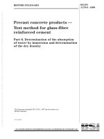
3.1.1
Image
binary data of a specified size
BS EN 62056-6-2:2016
IEC 62056-6-2:2016 © IEC 2016
– 17 –
Note 1 to entry: An Image can be seen as a container. It may consist of one or multiple elements
(image_to_activate) which are transferred, verified and activated together.
3.1.2
ImageSize
size of the whole Image to be transferred
Note 1 to entry:
ImageSize is expressed in octets.
3.1.3
ImageBlock
part of the Image of size ImageBlockSize
Note 1 to entry:
The Image is transferred in ImageBlocks. Each block is identified by its ImageBlockNumber.
3.1.4
ImageBlockSize
size of ImageBlock expressed in octets
3.1.5
ImageBlockNumber
identifier of an ImageBlock. ImageBlocks are numbered sequentially, starting from 0.
The meaning of the definitions above is illustrated in Figure 1.
Image
ImageBlock 0
ImageBlockSize
ImageBlock 1
ImageBlock 2
ImageSize
ImageBlock 3
...
ImageBlock n-1
IEC
Figure 1 – Meaning of the definitions concerning the Image
3.2
Terms and definitions related to the S-FSK PLC setup classes (see 5.8)
3.2.1
initiator
user-element of a client System Management Application Entity (SMAE)
Note 1 to entry:
The initiator uses the CIASE and xDLMS ASE and is identified by its system title.
[SOURCE: IEC 61334-4-511:2000, 3.8.1]
3.2.2
active initiator
initiator which issues or has last issued a CIASE Register request when the server is in the
unconfigured state
– 18 –
BS EN 62056-6-2:2016
IEC 62056-6-2:2016 © IEC 2016
[SOURCE: IEC 61334-4-511:2000, 3.9.1]
3.2.3
new system
server system which is in the unconfigured state: its MAC address equals "NEW-address"
[SOURCE: IEC 61334-4-511:2000, 3.9.3]
3.2.4
new system title
system-title of a new system
Note 1 to entry:
This is the system title of a system, which is in the new state.
[SOURCE: IEC 61334-4-511:2000, 3.9.4]
3.2.5
registered system
server system which has an individual valid MAC address (therefore, different from "NEW
Address", see IEC 61334-5-1:2001: Medium Access Control)
[SOURCE: IEC 61334-4-511:2000, 3.9.5]
3.2.6
reporting system
server system which issues a DiscoverReport
[SOURCE:
IEC 61334-4-511:2000,
IEC 61334-4-511:2000]
3.9.6,
modified,
to
correct
an
error
in
3.2.7
sub-slot
time needed to transmit two bytes by the physical layer
Note 1 to entry:
Timeslots are divided to sub-slots in the RepeaterCall mode of the physical layer.
3.2.8
timeslot
time needed to transmit a physical frame
Note 1 to entry: As specified in IEC 61334-5-1, 3.3.1, a physical frame comprises 2 bytes preamble, 2 bytes start
subframe delimiter, 38 bytes PSDU and 3 bytes pause.
3.3
Terms and definitions related to the PRIME NB OFDM PLC setup ICs (see 5.10)
Definitions related to the physical layer
3.3.1
base node
master node, which controls and manages the resources of a subnetwork
[SOURCE: ITU-T G.9904:2012, 3.2.1]
3.3.2
beacon slot
location of the beacon PDU within a frame
[SOURCE: ITU-T G.9904:2012, 3.2.2]