Bsi bs en 62056 8 3 2013
Bạn đang xem bản rút gọn của tài liệu. Xem và tải ngay bản đầy đủ của tài liệu tại đây (1.57 MB, 56 trang )
BS EN 62056-8-3:2013
BSI Standards Publication
Electricity metering
data exchange — The
DLMS/COSEM suite
Part 8-3: Communication profile
for PLC S-FSK neighbourhood
networks
BRITISH STANDARD
BS EN 62056-8-3:2013
National foreword
This British Standard is the UK implementation of EN 62056-8-3:2013. It is
identical to IEC 62056-8-3:2013.
The UK participation in its preparation was entrusted to Technical
Committee PEL/13, Electricity Meters.
A list of organizations represented on this committee can be obtained on
request to its secretary.
This publication does not purport to include all the necessary provisions of
a contract. Users are responsible for its correct application.
© The British Standards Institution 2013.
Published by BSI Standards Limited 2013
ISBN 978 0 580 75067 0
ICS 17.220.01; 35.110; 91.140.50
Compliance with a British Standard cannot confer immunity from
legal obligations.
This British Standard was published under the authority of the
Standards Policy and Strategy Committee on 30 September 2013.
Amendments/corrigenda issued since publication
Date
Text affected
BS EN 62056-8-3:2013
EN 62056-8-3
EUROPEAN STANDARD
NORME EUROPÉENNE
EUROPÄISCHE NORM
August 2013
ICS 17.220; 35.110; 91.140.50
English version
Electricity metering data exchange The DLMS/COSEM suite Part 8-3: Communication profile for PLC S-FSK neighbourhood networks
(IEC 62056-8-3:2013)
Echange des données de comptage de
l'électricité La suite DLMS/COSEM Partie 8-3: Profil de communication pour
réseaux de voisinage CPL S-FSK
(CEI 62056-8-3:2013)
Datenkommunikation der elektrischen
Energiemessung DLMS/COSEM Teil 8-3: PLC S-FSK Spezifikation für
Areal-Netze
(IEC 62056-8-3:2013)
This European Standard was approved by CENELEC on 2013-06-20. CENELEC members are bound to comply
with the CEN/CENELEC Internal Regulations which stipulate the conditions for giving this European Standard
the status of a national standard without any alteration.
Up-to-date lists and bibliographical references concerning such national standards may be obtained on
application to the CEN-CENELEC Management Centre or to any CENELEC member.
This European Standard exists in three official versions (English, French, German). A version in any other
language made by translation under the responsibility of a CENELEC member into its own language and notified
to the CEN-CENELEC Management Centre has the same status as the official versions.
CENELEC members are the national electrotechnical committees of Austria, Belgium, Bulgaria, Croatia, Cyprus,
the Czech Republic, Denmark, Estonia, Finland, Former Yugoslav Republic of Macedonia, France, Germany,
Greece, Hungary, Iceland, Ireland, Italy, Latvia, Lithuania, Luxembourg, Malta, the Netherlands, Norway, Poland,
Portugal, Romania, Slovakia, Slovenia, Spain, Sweden, Switzerland, Turkey and the United Kingdom.
CENELEC
European Committee for Electrotechnical Standardization
Comité Européen de Normalisation Electrotechnique
Europäisches Komitee für Elektrotechnische Normung
CEN-CENELEC Management Centre: Avenue Marnix 17, B - 1000 Brussels
© 2013 CENELEC -
All rights of exploitation in any form and by any means reserved worldwide for CENELEC members.
Ref. No. EN 62056-8-3:2013 E
BS EN 62056-8-3:2013
EN 62056-8-3:2013
-2-
Foreword
The text of document 13/1526/FDIS, future edition 1 of IEC 62056-8-3, prepared by IEC/TC 13 "Electrical
energy measurement, tariff- and load control" was submitted to the IEC-CENELEC parallel vote and
approved by CENELEC as EN 62056-8-3:2013.
The following dates are fixed:
•
latest date by which the document has
to be implemented at national level by
publication of an identical national
standard or by endorsement
(dop)
2014-03-20
•
latest date by which the national
standards conflicting with the
document have to be withdrawn
(dow)
2016-06-20
Attention is drawn to the possibility that some of the elements of this document may be the subject of
patent rights. CENELEC [and/or CEN] shall not be held responsible for identifying any or all such patent
rights.
Endorsement notice
The text of the International Standard IEC 62056-8-3:2013 was approved by CENELEC as a European
Standard without any modification.
In the official version, for Bibliography, the following note has to be added for the standard indicated:
IEC 61334-4-512:2001
NOTE Harmonized as EN 61334-4-512:2002 (not modified).
BS EN 62056-8-3:2013
EN 62056-8-3:2013
-3-
Annex ZA
(normative)
Normative references to international publications
with their corresponding European publications
The following documents, in whole or in part, are normatively referenced in this document and are
indispensable for its application. For dated references, only the edition cited applies. For undated
references, the latest edition of the referenced document (including any amendments) applies.
NOTE When an international publication has been modified by common modifications, indicated by (mod), the relevant EN/HD
applies.
Publication
Year
Title
EN/HD
Year
IEC 60050
Series International Electrotechnical Vocabulary
(IEV)
-
-
IEC 61334-4-1
1996
Distribution automation using distribution line EN 61334-4-1
carrier systems Part 4: Data communication protocols Section 1: Reference model of the
communication system
1996
IEC 61334-4-32
1996
Distribution automation using distribution line EN 61334-4-32
carrier systems Part 4: Data communication protocols Section 32: Data link layer - Logical link
control (LLC)
1996
IEC 61334-4-511
2000
Distribution automation using distribution line EN 61334-4-511
carrier systems Part 4-511: Data communication protocols Systems management - CIASE protocol
2000
IEC 61334-5-1
2001
Distribution automation using distribution line EN 61334-5-1
carrier systems Part 5-1: Lower layer profiles - The spread
frequency shift keying (S-FSK) profile
2001
IEC/TR 62051
1999
Electricity metering - Glossary of terms
-
-
IEC/TR 62051-1
+ corr. June
2004
2005
Electricity metering - Data exchange for meter reading, tariff and load control - Glossary of
terms Part 1: Terms related to data exchange with
metering equipment using DLMS/COSEM
-
IEC 62056-5-3
2013
Electricity metering data exchange - The
DLMS/COSEM suite Part 5-3: DLMS/COSEM application layer
EN 62056-5-3
2013
IEC 62056-6-2
2013
Electricity metering data exchange - The
DLMS/COSEM suite Part 6-2: COSEM interface classes
EN 62056-6-2
2013
IEC 62056-46
+ A1
2002
2006
Electricity metering - Data exchange for meter EN 62056-46
reading, tariff and load control + A1
Part 46: Data link layer using HDLC protocol
2002
2007
ISO/IEC 8802-2
+ corr. October
1998
2000
Information technology - Telecommunications and information exchange between systems Local and metropolitan area networks Specific requirements Part 2: Logical link control
-
–2–
BS EN 62056-8-3:2013
62056-8-3 © IEC:2013
CONTENTS
1
Scope ............................................................................................................................... 6
2
Normative references ....................................................................................................... 6
3
Terms, definitions and abbreviations ................................................................................ 7
4
3.1 Terms and definitions .............................................................................................. 7
3.2 Abbreviations .......................................................................................................... 8
Targeted communication environments ............................................................................. 9
5
Reference model ............................................................................................................ 11
6
The physical layer (PhL) ................................................................................................. 11
7
The data link layer .......................................................................................................... 12
8
7.1 General ................................................................................................................. 12
7.2 The MAC sublayer ................................................................................................. 12
7.3 The connectionless LLC sublayer .......................................................................... 12
7.4 The HDLC based LLC sublayer ............................................................................. 13
7.5 Co-existence of the connectionless and the HDLC based LLC sublayers ............... 13
The application layer (AL) ............................................................................................... 14
9
The application process (AP) .......................................................................................... 14
10 The Configuration Initiation Application Service Element (CIASE) .................................. 14
10.1
10.2
10.3
10.4
10.5
10.6
10.7
Overview ............................................................................................................... 14
The Discover service ............................................................................................. 14
The Register service ............................................................................................. 15
The Ping Service ................................................................................................... 15
The RepeaterCall service ...................................................................................... 17
The ClearAlarm service ......................................................................................... 19
The Intelligent Search Initiator process ................................................................. 21
10.7.1 General ..................................................................................................... 21
10.7.2 Operation .................................................................................................. 21
10.8 The Discovery and Registration process ................................................................ 24
10.9 Abstract and transfer syntax .................................................................................. 28
11 Addressing ..................................................................................................................... 28
11.1 General ................................................................................................................. 28
11.2 IEC 61334-5-1 MAC addresses ............................................................................. 28
11.3 Reserved special LLC addresses .......................................................................... 28
11.3.1 General ..................................................................................................... 28
11.3.2 Reserved addresses for the IEC 61334-4-32 LLC sublayer ........................ 29
11.3.3 Reserved addresses for the HDLC based LLC sublayer ............................. 29
11.3.4 Source and destination APs and addresses of CI-PDUs ............................ 30
12 Specific considerations / constraints for the IEC 61334-4-32 LLC sublayer based
profile ............................................................................................................................. 31
12.1
12.2
12.3
12.4
12.5
12.6
Establishing application associations ..................................................................... 31
Application association types, confirmed and unconfirmed xDLMS services .......... 33
xDLMS client/server type services ......................................................................... 33
Releasing application associations ........................................................................ 33
Service parameters of the COSEM-OPEN / -RELEASE / -ABORT services............ 34
The EventNotification service and the TriggerEventNotificationSending
service .................................................................................................................. 34
BS EN 62056-8-3:2013
62056-8-3 © IEC:2013
–3–
12.7 Transporting long messages .................................................................................. 35
12.8 Broadcasting ......................................................................................................... 35
13 Specific considerations / constraints for the HDLC LLC sublayer based profile ............... 35
13.1
13.2
13.3
13.4
Establishing Application Associations .................................................................... 35
Application association types, confirmed and unconfirmed xDLMS services .......... 36
xDLMS client/server type services ......................................................................... 37
Correspondence between AAs and data link layer connections, releasing
AAs ....................................................................................................................... 37
13.5 Service parameters of the COSEM-OPEN/ -RELEASE/ -ABORT services .............. 37
13.6 The EventNotification service and protocol ............................................................ 37
13.7 Transporting long messages .................................................................................. 37
13.8 Broadcasting ......................................................................................................... 37
14 Abstract syntax of CIASE APDUs ................................................................................... 37
Annex A (informative) S-FSK PLC encoding examples ......................................................... 39
Bibliography .......................................................................................................................... 51
Index .................................................................................................................................... 52
Figure 1 – Communication architecture ................................................................................. 10
Figure 2 – The DLMS/COSEM S-FSK PLC communication profile ......................................... 11
Figure 3 – Co-existence of the connectionless and the HDLC based LLC sublayers.............. 13
Figure 4 – Intelligent Search Initiator process flow chart ....................................................... 22
Figure 5 – The Discovery and Registration process .............................................................. 25
Figure 6 – MSC for the discovery and registration process .................................................... 32
Figure 7 – MSC for successful confirmed AA establishment .................................................. 32
Figure 8 – MSC for releasing an Application Association ...................................................... 34
Figure 9 – MSC for an EventNotification service ................................................................... 35
Figure 10 – MSC for the Discovery and Registration process ................................................ 36
Figure 11 – MSC for successful confirmed AA establishment and the GET service ............... 36
Table 1 – Service parameters of the Discover service primitives ........................................... 15
Table 2 – Service parameters of the Register service primitives ........................................... 15
Table 3 – Service parameters of the PING service primitives ................................................ 16
Table 4 – Service parameters of the RepeaterCall service primitives .................................... 17
Table 5 – Service parameters of the ClearAlarm service primitives ....................................... 20
Table 6 – MAC addresses ..................................................................................................... 28
Table 7 – Reserved IEC 61334-4-32 LLC addresses on the client side ................................. 29
Table 8 – Reserved IEC 61334-4-32 LLC addresses on the server side ................................ 29
Table 9 – Reserved HDLC based LLC addresses on the client side ...................................... 29
Table 10 – Reserved HDLC based LLC addresses on the server side ................................... 29
Table 11 – Source and Destination APs and addresses of CI-PDUs ...................................... 31
Table 12 – Application associations and data exchange in the S-FSK PLC profile using
the connectionless LLC sublayer .......................................................................................... 33
–6–
BS EN 62056-8-3:2013
62056-8-3 © IEC:2013
ELECTRICITY METERING DATA EXCHANGE –
THE DLMS/COSEM SUITE –
Part 8-3: Communication profile for PLC S-FSK neighbourhood networks
1
Scope
This part of IEC 62056 specifies the DLMS/COSEM PLC S-SFK communication profile for
neighbourhood networks.
It uses standards established by IEC TC 57 in the IEC 61334 series, Distribution automation
using distribution line carrier systems and it specifies extensions to some of those standards.
2
Normative references
The following documents, in whole or in part, are normatively referenced in this document and
are indispensable for its application. For dated references, only the edition cited applies. For
undated references, the latest edition of the referenced document (including any
amendments) applies.
IEC 60050
(all
parts),
International
)
Electrotechnical
Vocabulary
(available
at
IEC 61334-4-1:1996, Distribution automation using distribution line carrier systems – Part 4:
Data communication protocols – Section 1: Reference model of the communication system
IEC 61334-4-32:1996, Distribution automation using distribution line carrier systems – Part 4:
Data communication protocols – Section 32: Data link layer – Logical link control (LLC)
IEC 61334-4-511:2000, Distribution automation using distribution line carrier systems –
Part 4-511: Data communication protocols – Systems management – CIASE protocol
IEC 61334-5-1:2001, Distribution automation using distribution line carrier systems – Part 5-1:
Lower layer profiles – The spread frequency shift keying (S-FSK) profile
IEC/TR 62051:1999, Electricity metering – Glossary of terms
IEC/TR 62051-1:2004, Electricity metering – Data exchange for meter reading, tariff and load
control – Glossary of terms – Part 1: Terms related to data exchange with metering equipment
using DLMS/COSEM
IEC 62056-46:2002, Electricity metering – Data exchange for meter reading, tariff and load
control – Part 46: Data link layer using HDLC protocol
Amendment 1:2006
IEC 62056-5-3:—, Electricity metering data exchange – The DLMS/COSEM suite – Part 5-3:
DLMS/COSEM application layer 2
___________
2
To be published simultaneously with this part of IEC 62056.
BS EN 62056-8-3:2013
62056-8-3 © IEC:2013
–7–
IEC 62056-6-2:—, Electricity metering data exchange – The DLMS/COSEM suite – Part 6-2:
COSEM interface classes 3
ISO/IEC 8802-2:1998, Information technology – Telecommunications and information
exchange between systems – Local and metropolitan area networks – Specific requirements –
Part 2: Logical link control
NOTE
3
See also the Bibliography.
Terms, definitions and abbreviations
For the purposes of this document, the terms and definitions given in IEC 60050-300,
IEC/TR 62051 and IEC/TR 62051-1 and the following apply.
Where there is a difference between the definitions in the glossary and those contained in
product standards produced by TC 13, then the latter shall take precedence in applications of
the relevant standard.
3.1
Terms and definitions
3.1.1
initiator
user-element of a client System Management Application Entity (SMAE). It uses the CIASE
and xDLMS ASE and it is identified by its system title
[SOURCE: IEC 61334-4-511:2000, 3.8.1, modified]
3.1.2
active initiator
initiator, which issues or has last issued a CIASE Register request when the server is in the
unconfigured state
[SOURCE: IEC 61334-4-511:2000, 3.9.1]
3.1.3
new system
server system, which is in the unconfigured state: its MAC address equals "NEW-address"
[SOURCE: IEC 61334-4-511:2000, 3.9.3]
3.1.4
new system title
system-title of a new system
Note 1 to entry: This is the system title of a system, which is in the new state.
[SOURCE: IEC 61334-4-511:2000, 3.9.4, modified]
3.1.5
registered system
server system, which has an individual, valid MAC address
Note 1 to entry: Therefore,
Access Control.
this MAC address is different from "NEW Address", see IEC 61334-5-1: Medium
[SOURCE: IEC 61334-4-511:2000, 3.9.5, modified]
___________
3
To be published simultaneously with this part of IEC 62056.
–8–
BS EN 62056-8-3:2013
62056-8-3 © IEC:2013
3.1.6
reporting system
server system, which issues a DiscoverReport
[SOURCE: IEC 61334-4-511:2000, 3.9.6, modified]
3.1.7
sub-timeslot
the time needed to transmit two bytes by the physical layer
Note 1 to entry: Timeslots are divided to sub-slots in the RepeaterCall mode of the physical layer.
3.1.8
timeslot
the time needed to transmit a physical frame
Note 1 to entry: As specified in IEC 61334-5-1:2001, 3.3.1, a physical frame comprises 2 bytes preamble, 2 bytes
start subframe delimiter, 38 bytes PSDU and 3 bytes pause.
3.2
Abbreviations
.cnf
.confirm service primitive
.ind
.indication service primitive
.req
.request service primitive
.res
.response service primitive
AA
Application Association
AARE
A-Associate Response – an APDU of the ACSE
AARQ
A-Associate Request – an APDU of the ACSE
ACSE
Association Control Service Element
AES
Advanced Encryption Standard
AL
Application Layer
AP
Application Process
APDU
Application Layer Protocol Data Unit
ASE
Application Service Element
ASO
Application service Object
A-XDR
Adapted Extended Data Representation
CIASE
Configuration Initiation Application Service Element
CI-PDU
CIASE PDU
Client
A station, asking for services. In the case of the 3-layer, CO HDLC based
profile it is the master station
COSEM
Companion Specification for Energy Metering
DA
Destination Address
DLMS
Device Language Message Specification
DLMS UA
DLMS User Association
FCS
Frame Check Sequence
GCM
Galois/Counter Mode, an algorithm for authenticated encryption with
associated data
HCS
Header Check Sequence
HDLC
High-level Data Link Control
HES
(Metering) Head End System
ISO
International Organization for Standardization
BS EN 62056-8-3:2013
62056-8-3 © IEC:2013
–9–
LLC
Logical Link Control (Sublayer)
LN
Local Network
LNAP
Local Network Access Point
L-SAP
LLC sublayer Service Access Point
LSDU
LLC Service Data Unit
LV
Low voltage
MAC
Medium Access Control (sublayer)
MPDU
MAC Layer Protocol Data Unit
MSC
Message Sequence Chart
NN
Neighbourhood Network
NNAP
Neighbourhood Network Access Point
NS
Number of subframes (S-FSK MAC sublayer)
OSI
Open System Interconnection
PDU
Protocol Data Unit
PhL
Physical Layer
PLC
Power Line Carrier
PSDU
Physical Layer Service Data Unit
RDR
Reply Data on Request (used in IEC 61334-4-32)
RLRE
A-Release Response – an APDU of the ACSE
RLRQ
A-Release Request – an APDU of the ACSE
SA
Source Address
SAP
Service Access Point
SDN
Send Data Non-acknowledged (used in IEC 61334-4-32)
SDU
Service Data Unit
SMAE
Systems Management Application Entity
SMAP
Systems Management Application Process
SNRM
Set Normal Response Mode (a HDLC frame type)
4
Targeted communication environments
The DLMS/COSEM PLC S-FSK communication profile is intended for remote data exchange
on Neighbourhood Networks (NN) between Neighbourhood Network Access Points (NNAP)
and Local Network Access Points (LNAPs) or End Devices using S-FSK power line carrier
technology over the low voltage electricity distribution network as a communication medium.
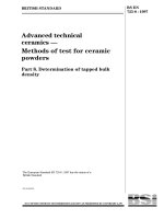
The functional reference architecture is shown in Figure 1.
BS EN 62056-8-3:2013
62056-8-3 © IEC:2013
– 10 –
Electricity Metering End Device
Meter application functions
I
Meter communication functions
M
L
NN
LN
C
Local Network Access Point (LNAP)
N
C
Neigbourhood Network Access Point (NNAP)
WAN
AMI Head End System
IEC 1149/13
Figure 1 – Communication architecture
End devices – typically electricity meters – comprise application functions and communication
functions. They may be connected directly to the NNAP via the C interface, or to an LNAP via
an M interface, while the LNAP is connected to the NNAP via the C interface. The LNAP
function may be co-located with the metering functions.
A NNAP comprises gateway functions and it may comprise concentrator functions. Upstream,
it is connected to the Metering Head End System (HES) using suitable communication media
and protocols.
End devices and LNAPs may communicate to different NNAPs, but to one NNAP only at a
time. From the PLC communication point of view, the NNAP acts as an initiator while end
devices and LNAPs act as responders.
NNAPs and similarly LNAPs may communicate to each other, but this is out of the scope of
this standard, which covers the C interface only.
When the NNAP has concentrator functions, it acts as a COSEM client. When the NNAP has
gateway functions only, then the HES acts as a COSEM client. The end devices or the LNAPs
act as COSEM servers.
BS EN 62056-8-3:2013
62056-8-3 © IEC:2013
5
– 11 –
Reference model
NOTE
This clause is partly based on IEC 61334-4-1:1996, Clause 3.
The reference model of the DLMS/COSEM PLC S-FSK communication profile is shown in
Figure 2. It is based on a simplified – or collapsed – three-layer OSI architecture. The layers
are the physical layer, the data link layer and the application layer. The data link layer is split
to the MAC sublayer and the LLC sublayer.
COSEM Application Process
IEC 62056-6-1, IEC 62056-6-2
System Management Application Process (SMAP)
System Management
Application Entity
(SMAE)
IEC 61334-5-1
Configuration Initiation ASE
(CIASE)
IEC 61334-4-511
with extensions
DLMS/COSEM Application layer
ACSE and xDLMS ASE
IEC 62056-5-3
ACSE and xDLMS APDUs
carried by
Connectionless DL-Data and DL-Reply services or
Connection oriented DL-Data services
CI-PDUs
carried by
Connectionless DL-Data services
Data link layer
MA-Sync.ind
Credit
management
HDLC based LLC sublayer (CO / CL)
IEC 62056-46
(ISO/IEC 8802-2 Class I over HDLC)
Connectionless LLC sublayer
IEC 61334-4-32
MA-Data services
S-FSK MAC sub-layer
IEC 61334-5-1 clause 4 with extensions
Phy-AskForRepeaterCall
P-Data services
P-Sync services
S-FSK Physical layer
IEC 61334-5-1 clause 3
IEC 1150/13
Figure 2 – The DLMS/COSEM S-FSK PLC communication profile
6
The physical layer (PhL)
The PhL provides the interface between the equipment and the physical transmission medium
that is the distribution network. It transports binary information from the source to the
destination.
– 12 –
BS EN 62056-8-3:2013
62056-8-3 © IEC:2013
The PhL in this profile is as specified in IEC 61334-5-1:2001, Clause 3. It provides the
following services to its service user MAC sublayer:
•
P-Data services to transfer MPDUs to (a) peer MAC sublayer entity(ies) using the LV
distribution network as the transport medium;
•
P-Sync services to allow the MAC sublayer entity to ask for a new synchronization and to
be informed of a change in the synchronization state of the PL. These services are used
locally by the MAC sublayer.
See IEC 61334-5-1:2001, 3.4.
7
7.1
The data link layer
General
The data link layer consists of two sublayers: the Medium Access Control (MAC) and the
Logical Link Control (LLC) sublayer.
The MAC sublayer handles access to the physical medium and provides physical device
addressing. The decision to access the medium is made by the initiator, directly for its own
MAC sublayer, or indirectly for other MAC sublayers that are requested to transmit a response
to a request sent previously by the initiator.
The LLC sublayer controls the logical links.
There are two LLC sublayer alternatives available:
•
the connectionless LLC sublayer, as specified in IEC 61334-4-32;
•
the LLC sublayer using the HDLC based data link layer, as specified in IEC 62056-46.
7.2
The MAC sublayer
The MAC sublayer of the DLMS/COSEM S-FSK PLC communication profile is as specified in
IEC 61334-5-1:2001, Clause 4. It provides the following services to its service user LLC
sublayer:
•
the MA-Data services. These services allow the LLC sublayer entity to exchange LLC data
units with peer LLC sublayer entities. See IEC 61334-5-1:2001, 4.1.3.1;
•
the MA-Sync.indication service. This allows the SMAE entity to be informed of the
synchronization and configuration status of the device. See IEC 61334-5-1:2001, 4.1.3.2.
7.3
The connectionless LLC sublayer
The connectionless LLC sublayer is as specified in IEC 61334-4-32. It is derived from
ISO/IEC 8802-2 – similar to Class III operation – and it performs the following functions:
•
addressing of application entities within the equipment;
•
sending data with no acknowledgement (SDN);
•
reply data on request (RDR).
It provides the following services:
•
DL-Data services for transporting CI-PDUs, ACSE APDUs and client-server type xDLMS
APDUs;
•
DL-Reply services for asking the remote LLC sublayer entity to send a previously
prepared LSDU;
•
DL-Update-Reply services to prepare the LSDUs to be transferred using the DL-Reply
services.
BS EN 62056-8-3:2013
62056-8-3 © IEC:2013
– 13 –
For more details, see IEC 61334-4-32:1996, 2.1.
7.4
The HDLC based LLC sublayer
The HDLC based LLC sublayer is as specified in IEC 62056-46.
As explained in IEC 62056-46:2002, 4.1 and 4.2, this sublayer can also be divided to two
sublayers:
•
the LLC sublayer based on ISO/IEC 8802-2. Here, it is used in an extended Class I
operation. The only role of this sublayer is to select the DLMS/COSEM Application layer
by using a specific LLC address. The LLC services are provided by the HDLC based MAC
sublayer;
•
the MAC sublayer, based on the HDLC protocol. It provides addressing of application
entities within the equipment.
NOTE In this profile, there are two MAC sublayers. The HDLC MAC sublayer provides reliable LLC data transport
and segmentation. The Medium Access Control functionality is provided by the S-FSK MAC sublayer specified in
7.2.
The HDLC based LLC sublayer provides the following services:
•
DL-Connect services to connect and to disconnect the data link layer;
•
connectionless DL-Data services for transporting CI-PDUs, ACSE APDUs and xDLMS
APDUs;
•
connection oriented DL-Data services for transporting ACSE APDUs and xDLMS APDUs.
These services provide reliable data transport and support segmentation to carry long
messages, in a transparent manner for the application layer.
7.5
Co-existence of the connectionless and the HDLC based LLC sublayers
The frames of the connectionless LLC sublayer and the HDLC based LLC sublayer can be
distinguished from each other as shown in Figure 3. This allows systems using the two
profiles to co-exist on the same network.
DSAP address field
Control field
SSAP address field
LSB
IEC 61334-4-32
LLC frame header: MSB = 1
1 C C C/R Q Q Q Q
D D D D D D D D
S S S S S S S S
Frame format
Flag 7E
LSB
IEC 62056-46
Data link layer header: MSB = 0
Legend:
C: Command subfield
C/R: Command / response bit
QQQQ: Qualifier subfield
DDDDDDDD: Destination address
SSSSSSSS: Source address
S: Segmentation
L: Length
0 1 1 1 1 1 1 0
1 0 1 0 S L L L
L L L L L L L L
IEC 1151/13
Figure 3 – Co-existence of the connectionless and the HDLC based LLC sublayers
– 14 –
8
BS EN 62056-8-3:2013
62056-8-3 © IEC:2013
The application layer (AL)
Concerning the application layer, the DLMS/COSEM Application layer as specified in
IEC 62056-5-3 applies. It provides services to the COSEM application process (AP) and uses
the services of the connectionless or the HDLC based LLC sublayer.
9
The application process (AP)
On the server side, the COSEM device- and object model – as specified in IEC 62056-6-2 –
applies. Each logical device represents an AP.
The client side APs make use of the resources of the server side AP. A physical device may
host one or more client APs.
10 The Configuration Initiation Application Service Element (CIASE)
NOTE
This clause is based on IEC 61334-4-511 and constitutes an extension to it.
10.1
Overview
One of the activities of systems management is open system initialisation and / or
modification. This is provided by the Configuration Initiation ASE (CIASE). It is specified in
IEC 61334-4-511 with the extensions specified below.
The CIASE services are the following:
•
the Discover service;
•
the Register service;
•
the PING service;
•
the RepeaterCall service; and
•
the ClearAlarm service.
The three latter services, together with the Intelligent Search Initiator process specified in
10.7, constitute upper compatible functional extensions to IEC 61334-4-511.
The CIASE uses the connectionless DL-Data services of the LLC sublayer.
10.2
The Discover service
NOTE In this document, the description of the CIASE services follows the presentation style used for the
DLMS/COSEM services. For the notation used, see IEC 62056-5-3:—, 6.1.
The Discover service is used to discover new systems or systems, which are in alarm state. It
is specified in IEC 61334-4-511:2000, 7.1. The Discover service primitives shall provide the
parameters as shown in Table 1.
BS EN 62056-8-3:2013
62056-8-3 © IEC:2013
– 15 –
Table 1 – Service parameters of the Discover service primitives
Discover
DiscoverReport
.request
.indication
.response
.confirm
M
M (=)
–
–
Response_Probability
M
M (=)
Allowed_Time_Slots
M
M (=)
DiscoverReport_Initial_Credit
M
M (=)
IC_Equal_Credit
M
M (=)
–
–
S
S (=)
M
M (=)
C
C (=)
S
S (=)
M
M (=)
Argument
Result (+)
System_Title {System_Title}
–
–
Alarm_Descriptor
Result (-)
–
Argument_Error(s)
–
NOTE This Table 1 is included here for completeness and to correct some editorial errors
IEC 61334-4-511:2000, 7.1. For the description of the service parameters, see the clause referenced here.
10.3
in
The Register service
The Register service is used to perform system configuration. It assigns a MAC address to a
new system identified by its system title. It is specified in IEC 61334-4-511:2000, 7.2. The
Register service primitives shall provide the parameters as shown in Table 2.
Table 2 – Service parameters of the Register service primitives
.request
.indication
Active_Initiator_System_Title
M
M (=)
List_Of_Correspondence
M
M (=)
New_System_Title
M
M (=)
MAC_Address
M
M (=)
S
S
Argument
Result (+)
Result (–)
Argument_Error(s)
S
S
M
M (=)
NOTE This Table 2 is included here for completeness. For the
description of the service parameters, see IEC 61334-4-511:2000,
7.2.
NOTE 1 If a server in NEW state receives a correct Register service with its own server system title in it, it will be
registered, even if it did not receive a Discover service before.
NOTE 2
10.4
Only those servers in the NEW state can be registered.
The Ping Service
Function
The Ping service is used to check that a server system already registered is still present on
the network. It also allows verifying that the right physical device is linked to the right MAC
address. It also allows preventing the time_out_not_addressed timer to expire.
BS EN 62056-8-3:2013
62056-8-3 © IEC:2013
– 16 –
The process begins with a Ping.request service primitive issued by the active initiator. The
service contains the system title of the physical device pinged. The PingRequest CI-PDU is
carried by a DL-Data.request service primitive and it is sent to the MAC address assigned to
this system and to the server CIASE L-SAP.
If the system title carried by the Ping.indication service primitive is equal to the system title of
the server, the server shall respond with a Ping.response service primitive, carrying the
system title of the server. It is sent to the initiator CIASE L-SAP.
Semantics
The PING service primitives shall provide parameters as shown in Table 3.
Table 3 – Service parameters of the PING service primitives
Argument
.request
.indication
.response
.confirm
M
M (=)
-
-
–
–
S
S (=)
M
M (=)
S
S
M
M (=)
System_Title_Server
Result (+)
System_Title_Server
Result (–)
–
–
Argument_Error(s)
The System_Title_Server service parameter allows identifying a physical device concerned by
the Ping service. The destination MAC address in the DL-Data.request service primitive is
equal to the MAC address that has been assigned to this system using the Register service.
The Ping.response service primitive returns with « Result (+) » if the Ping.request service has
succeeded, i.e. the system title of the physical device at the given MAC address is equal to
the “System_Title_Server” carried by the Ping.request service primitive.
Otherwise, no response is sent by the server.
Use – Client side
The Ping.request service primitive is issued by the active initiator.
If the “System_Title_Server” service parameter is not valid, a local confirmation is sent
immediately with a negative result indicating the problem encountered (Ping-system-title-nok).
Otherwise, the CIASE forms a DL-Data.request PDU containing a PingRequest CI-PDU that
carries the System_Title_Server requested. It is sent to the physical device concerned by the
request.
Once the transmission of the PingRequest CI-PDU is over, the CIASE waits for a
DL-Data.indication service primitive containing a PingResponse CI-PDU from the physical
device pinged, during the necessary time that depends on the initial credit of the request.
If the CIASE receives a DL-Data.indication service primitive containing a PingResponse CIPDU before this delay is over, it sends to the initiator a confirmation with a positive result,
containing the service parameter returned by the server system.
If no DL-DATA.indication service primitive is received, the CIASE sends to the initiator a
confirmation with a negative result pointing out the absence of an answer (Ping-no-response).
BS EN 62056-8-3:2013
62056-8-3 © IEC:2013
– 17 –
Use – Server side
On the reception of a DL-Data.indication service primitive containing a PingRequest CI-PDU,
the CIASE checks that the System_Title_Server service parameter is correct and that it is
equal to its own system title.
If so, it invokes a Ping.response service primitive that includes its system title. The
PingResponse CI-PDU is carried by a DL-Data.request service primitive.
If the service parameter of the Ping.indication service primitive is not correct, no response is
sent.
Finally, if the System_Title_Server service parameter in the Ping.indication service primitive is
correct, but not equal to the system title of the physical device, no response is sent.
10.5
The RepeaterCall service
Function
The purpose of the RepeaterCall service is to adapt the repeater status of server systems
depending on the topology of the electrical network. It allows the automatic configuration of
the repeater status on the whole network.
In the RepeaterCall mode, the client and the servers transmit short frames – two bytes long
each – and measure the level of the signal to determine if a server system should be a
repeater or not.
Semantics
The RepeaterCall service primitives shall provide parameters as shown in Table 4.
Table 4 – Service parameters of the RepeaterCall service primitives
. request
. indication
Max_Adr_MAC
M
M (=)
Nb_Tslot_For_New
U
U (=)
Reception_Threshold
M
M (=)
S
S
Arguments
Result (+)
Result (-)
Argument_Error(s)
S
S
M
M
The Max_Adr_MAC service parameter allows calculating the number of timeslots used in the
RepeaterCall mode by the physical layer of the server systems registered to an initiator. It
corresponds to the largest server system MAC address that is stored by the initiator.
NOTE 1 The largest allowable server MAC address is 3071 (BFF), as the range C00...DFF is reserved for the
initiator, as specified in IEC 61334-5-1:2001, 4.3.7.7.1.
The value of Nb_Tslot is calculated from this information:
Nb _ Tslot = MaxAdrMax / 21 + 1
– 18 –
where
x
BS EN 62056-8-3:2013
62056-8-3 © IEC:2013
means the floor of x, the nearest integer ≤ x.
EXAMPLE 1
Max_Adr_MAC = 20 (20 servers on the network)
Nb _ Tslot = 20 / 21 + 1 = 1
Nb_Tslot = 1, with 1 sub-timeslot for the NNAP (concentrator) and 20 sub-timeslots for the servers.
EXAMPLE 2
Max_Adr_MAC = 21 (21 servers on the network)
Nb _ Tslot = 21 / 21 + 1 = 2
Nb_Tslot = 2:
1 timeslot with 1 sub-timeslot for the NNAP (concentrator) and 20 sub-timeslots for 20 servers;
1 timeslot with 1 sub-timeslot for one server.
The Nb_Tslot_For_New service parameter defines the number of timeslots used in the
RepeaterCall mode by the physical layer of the server systems in NEW state. If the value of
this service parameter is 0 (or not present) then the systems in NEW state are not allowed to
participate in the Repeater Call process.
The maximum number of timeslots used by the physical layer is equal to the sum of the
number of timeslots for the server systems registered and the number of timeslots for the
server systems in NEW state.
The Reception_Threshold service parameter defines the threshold of the signal level in dBμV,
necessary to validate a physical pattern in a Sub_Tslot when the physical layer is in the
RepeaterCall mode.
The Result (+) service parameter (positive result) indicates that the requested service has
succeeded.
The Result (–) service parameter (negative result) indicates that the requested service has
failed.
The “Arguments Error” indicates that at least one argument has a wrong value.
Use – Client side
The RepeaterCall service of the CIASE is invoked by the SMAP.
If any of the arguments is not valid, a confirmation is sent immediately with a negative result
indicating the problem encountered.
Otherwise, the CIASE forms a DL-Data.request service primitive containing a RepeaterCall
CI-PDU carrying the parameters requested. This request is sent to all server systems.
A positive confirmation is passed to the CIASE upon the reception of a DL-Data.cnf(+).
When this confirmation is received, the CIASE sends the Phy_AskForRepeaterCall.request
primitive allowing the activation of the RepeaterCall mode of the physical layer. The
parameters of this primitive are the following:
BS EN 62056-8-3:2013
62056-8-3 â IEC:2013
19
ã
Sub_Tslot position: on the client (initiator) side its value is 0;
•
Reception_Threshold.
NOTE 2
On the client side, the Reception_Threshold parameter has no significance.
Use – server side
On the server side, on the reception of a DL-Data.indication service primitive containing a
RepeaterCall CI-PDU, the CIASE verifies that the service parameters are correct.
If this is the case, it sends the Phy_AskForRepeaterCall.request primitive to activate the
RepeaterCall mode of the physical layer. The parameters of this primitive are the following:
•
Sub_Tslot position: A number expressed on two octets, between 0 and 65 535. The value
0 is reserved for the configuration of the NNAP (concentrator). The other values are
available for the configuration of server systems.
In the case of server systems registered by a NNAP (concentrator), Sub-Tslot takes the
value of the local MAC address of the server system, between 1 and Max_Adr_MAC. For
the server systems not registered, Sub_Tslot takes a random value between
Max_Adr_MAC and Max_Adr_MAC + (Nb_Tslot_For_New * 21).
NOTE 3
service.
•
Max_Adr_MAC and Nb_Tslot_For_New are the service parameters of the RepeaterCall.request
Reception_Threshold: This represents the signal level in dBμV. The default value is 104.
If the response to this request is negative, the command is cancelled. The following cases
lead to a failure:
•
the state of the physical layer is not correct (there is no physical synchronization);
•
the repeater status is never_repeater;
•
the parameters are incorrect.
The participation of the servers in the repeater call process and the effect of the process on
their repeater status depend on the repeater management variable (attribute 10 of the S-FSK
Phy&MAC setup object, see IEC 62056-6-2:—, 5.8.4) and the signal level heard:
•
servers configured as never repeater do not participate: they do not transmit during their
sub-timeslot and their repeater_status (attribute 11 of the S-FSK Phy&MAC setup object)
is not affected;
•
servers configured as always repeater participate: they transmit during their timeslot but
their repeater_status is not affected;
•
servers configured as dynamic repeater participate: they transmit during their subtimeslot, if they have not heard a signal before from the client or from any servers, which
is above the reception threshold. If during the whole repeater call process, a server does
not hear a signal from the client or from other servers, which is above the reception
threshold, then its repeater status will be TRUE: the server will repeat all frames. If a
server hears a signal from the client or from other servers, which is above the reception
threshold, then its repeater status will be FALSE: the server won't repeat any frames.
NOTE 4 If each server configured as dynamic repeater hears a signal, which is above the reception
threshold, this means that they are all close to a client, and no repetition is needed. So, none of them will
become a repeater.
10.6
The ClearAlarm service
Function
The ClearAlarm service allows clearing the alarm state in (a) server system(s), in a point-topoint or in a broadcast mode.
– 20 –
BS EN 62056-8-3:2013
62056-8-3 © IEC:2013
Semantics
The ClearAlarm service primitives shall provide parameters as shown in Table 5.
Table 5 – Service parameters of the ClearAlarm service primitives
.request
.indication
Alarm_Descriptor
S
S (=)
Alarm_Descriptor {Alarm_Descriptor}
S
S (=)
Alarm_Descriptor_List_And_Server_List
S
S (=)
System_Title {System_Title}
M
M (=)
Alarm_Descriptor {Alarm_Descriptor}
M
M (=)
S
S (=)
System_Title
M
M (=)
Alarm_Descriptor
M
M (=)
Result (+)
S
S
Result (-)
S
S
M
M
Arguments
Alarm_Descriptor_By_Server {Alarm_Descriptor_By_Server}
Arguments Error
This service provides four different possibilities:
•
the Alarm_Descriptor choice allows clearing a single alarm in all server systems. The
value of the Alarm_Descriptor parameter identifies the alarm to be cleared;
•
the Alarm_Descriptor {Alarm_Descriptor} choice allows clearing a list of alarms in all
server systems. The value of the Alarm_Descriptor {Alarm_Descriptor} parameter
identifies the list of alarms to be cleared;
•
the Alarm_Descriptor_List_And_Server_List choice allows clearing a common list of
alarms specified in the list of server systems specified. The System_Title {System_Title}
parameter identifies the list of server systems in which the alarms have to be cleared. The
value of the Alarm_Descriptor {Alarm_Descriptor} parameter identifies the list of alarms to
be cleared;
•
the Alarm_Descriptor_By_Server {Alarm_Descriptor_By_Server} choice allows clearing
one alarm specified in each server specified. The System_Title parameter identifies the
server system in which the alarm has to be cleared. The value of the Alarm_Descriptor
parameter identifies the alarm to be cleared.
As specified in IEC 61334-4-511:2000, 6.2.2, alarm descriptors should be specified in
companion specifications.
The Result (+) argument (positive result) indicates that the requested service has succeeded.
The Result (–) argument (negative result) indicates that the requested service has failed.
The “Argument Error(s)” indicates that at least one argument has a wrong value.
Use
The ClearAlarm CIASE service is invoked by the initiator.
If any of the service parameters is not valid, a confirmation is sent immediately with a
negative result indicating the problem encountered.
BS EN 62056-8-3:2013
62056-8-3 © IEC:2013
– 21 –
Otherwise, the CIASE forms a DL-Data.request service primitive containing a ClearAlarm
CI-PDU containing the parameters requested. This request is sent to the server system(s)
concerned by the request. A positive confirmation is sent upon the reception of a
DL-Data.cnf(+) service primitive.
On the server side, on the reception of a DL-Data.indication service primitive containing a
ClearAlarm CI-PDU, the CIASE verifies that the arguments are correct. If this is the case, it
clears the alarms corresponding to the list of alarms. Otherwise, the service is ignored.
10.7
The Intelligent Search Initiator process
10.7.1
General
The objective of the Intelligent Search Initiator process is to improve plug&play installation of
server systems, by ensuring that each server system is registered by the correct initiator.
When a new server system is placed on the network, it will be discovered and registered by
the first initiator it hears talking. It remains registered by that initiator as long as it keeps
receiving correct frames (the time_out_not_addressed timer does not expire). If there is
cross-talk on the network, the server system may be registered by the wrong initiator, i.e. one,
which is “heard” by the server system due to cross-talk.
When the Intelligent Search Initiator process is implemented in the server system, it is
capable to establish a list of all initiators it can “hear”, and to lock on the initiator with the best
signal level.
10.7.2
10.7.2.1
Operation
Flow chart
The intelligent search initiator process comprises two phases:
•
the Search Initiator phase;
•
the Check Initiator phase.
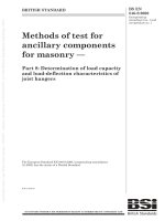
The Intelligent Search Initiator process is shown in Figure 4. See also Figure 5 showing the
complete discovery and registration process.
10.7.2.2
Process parameters
The Intelligent Search Initiator process is characterized by two parameters:
•
The search_initiator_time_out, defining the duration of the Search Initiator Phase. This
timeout is also used during the Check Initiator Phase, see 10.7.2.4;
The Search Initiator Phase shall be long enough to allow the server systems to hear all
the initiators around them and, when needed, to let sufficient time to start all the initiators
by the Head End System. However, this time should not be too long either, so that the
discovery phase could be executed correctly. The recommended value for this timeout is
10 minutes;
•
The search_initiator_threshold, defining the minimum signal level allowing a fast
synchronization.
The value of the search_initiator_threshold should be chosen so that the server systems next
to an initiator lock on it immediately, but the server systems a bit further away (maybe on
another network) do only lock on it after the search_initiator_time_out timer expires. The
default value is 98 dBμV.
BS EN 62056-8-3:2013
62056-8-3 © IEC:2013
– 22 –
NEW and UNLOCKED
mac_address = NEW
active_initiator = {system_title = 0, client_mac = 0, L_SAP = 0}
initiator_mac_address = NO_BODY
Save default values
SET synchronization_confirmation_timeout = 3-5 s
SET repeater status = never_repeater
Server system does not repeat and answer to any frames
Legend:
Valid frame
received?
No
SI_threshold: search_initiator_threshold
SI_time_out: search_initiator_time_out
Yes
START SI_time_out
Memorize {Signal level, initiator_mac_address}
Signal level
> SI_threshold
Fast Synchronization
No
Desynchronize
Yes
Yes
Lock on initiator (with strongest signal)
RESTORE default synchronization_confirmation_time_out
RESTORE default repeater status
START synchronization_confirmation_time_out
START time_out_frame_not_OK
Search
Initiator
Phase
SI_time_out
expired?
No
Valid frame
received?
No
Yes
RESTART SI_time_out
NEW and LOCKED
mac_adress = NEW
active_initiator = {system_title = 0, client_mac = valid, L_SAP = 0}
synchronization_locked = TRUE
initiator_mac_address = client_mac
START time_out_not_addressed
Valid frame received?
STOP all timers running
Check
Initiator
Phase
No
Yes
SI_time_out
expired?
RESTART SI_time_out
Yes
No
Registered?
No
Yes
STOP SI_time_out
REGISTERED and LOCKED
mac_adress = valid
active_initiator =
{system_title = valid, client_mac = valid, L_SAP = valid}
initiator_mac_address = client_mac
synchronization_locked = TRUE
START time_out_not_addressed
time_out_
not_addressed
expired?
Yes
No
IEC 1152/13
NOTE A valid frame is a frame in which either the source or the destination address is an initiator address, and
otherwise correct.
Figure 4 – Intelligent Search Initiator process flow chart
10.7.2.3
Search Initiator Phase
Initially, the server system is in the NEW and UNLOCKED state waiting to receive a valid
frame.
BS EN 62056-8-3:2013
62056-8-3 © IEC:2013
– 23 –
For the Search Initiator Phase, the synchronization_confirmation_time_out shall be reduced to
3-5 s. Otherwise, a server system would remain synchronized too long on a bad frame.
During this phase, a server system shall not repeat any frames. This is because if repetition
was allowed, it would have to repeat all frames, not only the frames from the closest initiator,
and so the other server systems next to it would listen to frames from a bad initiator with a
strong signal level. Therefore, the Intelligent Search Initiator algorithm can only be efficient if
all the server systems on a network have the algorithm implemented (otherwise, other server
systems could repeat frames and foul the signal level).
For the same reasons, a server system shall not transmit any frames during the Search
Initiator Phase:
•
it should not answer to a Discover request (It should be desynchronised before, except if
the signal level is good enough to allow fast synchronization. But in this case, the server
system is not in the Search Initiator Phase anymore but in the Check Initiator Phase);
•
it should not answer to a Register request either;
•
and in particular, it should not answer any ACSE or xDLMS service requests (this is
obvious because the server system is in the NEW state).
Notice that as soon as a server system becomes locked, it can repeat frames since it will only
accept frames from the good initiator. (It is even advised that it repeats frames, since it will
shorten the Search Initiator Phase for the other server systems).
Each time that the server system receives a frame, it checks the signal level and the MAC
addresses in it:
•
if none of the MAC addresses – source or destination – is an initiator MAC address, the
frame is considered as invalid; the server system immediately desynchronises in order to
listen to another frame;
•
if one of the MAC addresses is an initiator MAC address, and the signal level is good
enough (signal level > search_initiator_threshold – see 10.7.2.2) the server system locks
on that initiator. This is called Fast Synchronization. This occurs when the server system
is next to an initiator or to a server system that is already registered to that initiator. The
server system enters the Check Initiator Phase;
•
if one of the MAC addresses is an initiator MAC address but the signal level is not good
enough (signal level < search_initiator_threshold), the server system memorizes the
signal level and the MAC address, then desynchronizes immediately in order to listen to
another frame;
•
when the search_initiator_time_out expires, the server system locks to the initiator having
provided the best signal level.
At this point:
•
the default values of the synchronization_confirmation_time_out and the repeater status
are restored;
•
the synchronization_confirmation_time_out and the time_out_frame_not_OK timers are
initialised;
•
the search_initiator_time_out is restarted.
The server is in the NEW and LOCKED state and enters the Check Initiator Phase.
10.7.2.4
Check Initiator Phase
Once the server system is locked, it can be discovered and registered. The process is the
following:
•
the time_out_not_addressed timer is started;