Bsi bs en 62282 4 101 2014
Bạn đang xem bản rút gọn của tài liệu. Xem và tải ngay bản đầy đủ của tài liệu tại đây (1.68 MB, 58 trang )
BS EN 62282-4-101:2014
BSI Standards Publication
Fuel cell technologies
Part 4-101: Fuel cell power systems for
propulsion other than road vehicles and
auxiliary power units (APU) — Safety of
electrically powered industrial trucks
BRITISH STANDARD
BS EN 62282-4-101:2014
National foreword
This British Standard is the UK implementation of EN 62282-4-101:2014. It
is identical to IEC 62282-4-101:2014.
The UK participation in its preparation was entrusted to Technical
Committee GEL/105, Fuel cell technologies.
A list of organizations represented on this committee can be obtained on
request to its secretary.
This publication does not purport to include all the necessary provisions of
a contract. Users are responsible for its correct application.
© The British Standards Institution 2014.
Published by BSI Standards Limited 2014
ISBN 978 0 580 81618 5
ICS 27.070
Compliance with a British Standard cannot confer immunity from
legal obligations.
This British Standard was published under the authority of the
Standards Policy and Strategy Committee on 31 October 2014.
Amendments/corrigenda issued since publication
Date
Text affected
BS EN 62282-4-101:2014
EUROPEAN STANDARD
EN 62282-4-101
NORME EUROPÉENNE
EUROPÄISCHE NORM
October 2014
ICS 27.070
English Version
Fuel cell technologies - Part 4-101: Fuel cell power systems for
propulsion other than road vehicles and auxiliary power units
(APU) - Safety of electrically powered industrial trucks
(IEC 62282-4-101:2014)
Technologies des piles à combustible - Partie 4-101:
Systèmes à piles à combustible pour la propulsion, autres
que les véhicules routiers et groupes auxiliaires de
puissance (GAP) - Sécurité pour chariots de manutention
électriques
(CEI 62282-4-101:2014)
Brennstoffzellen-Technologien - Teil 4-101: Antriebe mit
Brennstoffzellen-Energiesystemen (mit Ausnahme von
Strenfahrzeugen und Hilfsantrieben) - Elektrisch
betriebene Flurfưrderfahrzeuge - Sicherheit
(IEC 62282-4-101:2014)
This European Standard was approved by CENELEC on 2014-09-16. CENELEC members are bound to comply with the CEN/CENELEC
Internal Regulations which stipulate the conditions for giving this European Standard the status of a national standard without any alteration.
Up-to-date lists and bibliographical references concerning such national standards may be obtained on application to the CEN-CENELEC
Management Centre or to any CENELEC member.
This European Standard exists in three official versions (English, French, German). A version in any other language made by translation
under the responsibility of a CENELEC member into its own language and notified to the CEN-CENELEC Management Centre has the
same status as the official versions.
CENELEC members are the national electrotechnical committees of Austria, Belgium, Bulgaria, Croatia, Cyprus, the Czech Republic,
Denmark, Estonia, Finland, Former Yugoslav Republic of Macedonia, France, Germany, Greece, Hungary, Iceland, Ireland, Italy, Latvia,
Lithuania, Luxembourg, Malta, the Netherlands, Norway, Poland, Portugal, Romania, Slovakia, Slovenia, Spain, Sweden, Switzerland,
Turkey and the United Kingdom.
European Committee for Electrotechnical Standardization
Comité Européen de Normalisation Electrotechnique
Europäisches Komitee für Elektrotechnische Normung
CEN-CENELEC Management Centre: Avenue Marnix 17, B-1000 Brussels
© 2014 CENELEC All rights of exploitation in any form and by any means reserved worldwide for CENELEC Members.
Ref. No. EN 62282-4-101:2014 E
BS EN 62282-4-101:2014
EN 62282-4-101:2014
-2-
Foreword
The text of document 105/506/FDIS, future edition 1 of IEC 6228-4-101, prepared by
IEC/TC 105 "Fuel cell technologies" was submitted to the IEC-CENELEC parallel vote and approved
by CENELEC as EN 62282-4-101:2014.
The following dates are fixed:
•
latest date by which the document has
to be implemented at national level by
publication of an identical national
standard or by endorsement
(dop)
2015-06-16
•
latest date by which the national
standards conflicting with the
document have to be withdrawn
(dow)
2017-09-16
Attention is drawn to the possibility that some of the elements of this document may be the subject of
patent rights. CENELEC [and/or CEN] shall not be held responsible for identifying any or all such
patent rights.
Endorsement notice
The text of the International Standard IEC 62282-4-101:2014 was approved by CENELEC as a
European Standard without any modification.
In the official version, for Bibliography, the following notes have to be added for the standards
indicated:
IEC 60034 Series
NOTE
Harmonised as EN 60034 Series.
IEC 60034-11
NOTE
Harmonised as EN 60034-11.
IEC 60079-20-1
NOTE
Harmonised as EN 60079-20-1.
IEC 60112
NOTE
Harmonised as EN 60112.
IEC 60243 Series
NOTE
Harmonised as EN 60243 Series.
IEC 60695-11-5
NOTE
Harmonised as EN 60695-11-5.
IEC 60812
NOTE
Harmonised as EN 60812.
IEC 62282-3-100
NOTE
Harmonised as EN 62282-3-100.
IEC 62282-5-1
NOTE
Harmonised as EN 62282-5-1.
ISO 16017-1
NOTE
Harmonised as EN ISO 16017-1.
BS EN 62282-4-101:2014
EN62282-4-101:2014
-3-
Annex ZA
(normative)
Normative references to international publications
with their corresponding European publications
The following documents, in whole or in part, are normatively referenced in this document and are
indispensable for its application. For dated references, only the edition cited applies. For undated
references, the latest edition of the referenced document (including any amendments) applies.
NOTE 1 When an International Publication has been modified by common modifications, indicated by (mod), the relevant
EN/HD applies.
NOTE 2 Up-to-date information on the latest versions of the European Standards listed in this annex is available here:
www.cenelec.eu.
Publication
Year
Title
IEC 60079-0
-
Explosive atmospheres
EN 60079-0
Part 0: Equipment - General requirements
-
IEC 60079-10-1
-
Explosive atmospheres
Part 10-1: Classification of areas Explosive gas atmospheres
EN 60079-10-1
-
IEC 60079-29-1
-
Explosive atmospheres
Part 29-1: Gas detectors - Performance
requirements of detectors for flammable
gases
EN 60079-29-1
-
IEC 60079-29-4
-
Explosive atmospheres
Part 29-4: Gas detectors - Performance
requirements of open path detectors for
flammable gases
EN 60079-29-4
-
IEC 60204-1
-
Safety of machinery - Electrical equipment EN 60204-1
of machines
Part 1: General requirements
IEC 60227-3
-
Polyvinyl chloride insulated cables of rated HD 21.3 S3
voltages up to and including 450/750 V
Part 3: Non-sheathed cables for fixed wiring
IEC 60227-5
-
Polyvinyl chloride insulated cables of rated voltages up to and including 450/750 V
Part 5: Flexible cables (cords)
-
IEC 60335-2-41
-
Household and similar electrical appliances EN 60335-2-41
– Safety
Part 2-41: Particular requirements for
pumps
-
IEC 60335-2-80
-
Safety of household and similar electrical EN 60335-2-80
appliances
Part 2-80: Particular requirements for fans
-
IEC 60364-4-41
(mod)
2005
Low-voltage electrical installations
HD 60364-4-41
Part 4-41: Protection for safety - Protection + corr. July
against electric shock
2007
2007
IEC 60529
-
Degrees of protection provided by
enclosures (IP Code)
-
1)
Superseded by EN 50525-2-31:2011.
EN/HD
EN 60529
Year
1)
-
-
BS EN 62282-4-101:2014
EN 62282-4-101:2014
-4-
Publication
Year
Title
EN/HD
Year
IEC 60584-1
-
Thermocouples
Part 1: Reference tables
EN 60584-1
-
IEC 60664-1
-
Insulation coordination for equipment within EN 60664-1
low-voltage systems
Part 1: Principles, requirements and tests
-
IEC 60695
Series
Fire hazard testing
EN 60695
Series
IEC 60695-1-30
-
Fire hazard testing
Part 1-30: Guidance for assessing the fire
hazard of electrotechnical products Preselection testing process - General
guidelines
EN 60695-1-30
-
IEC 60695-10-2
-
Fire hazard testing
EN 60695-10-2
Part 10-2: Guidance and test methods for
the minimization of the effects of abnormal
heat on electrotechnical products involved
in fires - Method for testing products made
from non-metallic materials for resistance to
heat using the ball pressure test
-
IEC 60695-11-4
-
Fire hazard testing
Part 11-4: Test flames - 50 W flame Apparatus and confirmational test method
EN 60695-11-4
-
IEC 60695-11-10
-
Fire hazard testing
Part 11-10: Test flames - 50 W horizontal
and vertical flame test methods
EN 60695-11-10
-
IEC 60730-1
(mod)
2013
Automatic electrical controls
Part 1: General requirements
EN 60730-1
IEC 60730-2-17
-
Automatic electrical controls for household and similar use
Part 2-17: Particular requirements for
electrically operated gas valves, including
mechanical requirements
-
IEC 60947-3
-
Low-voltage switchgear and controlgear
Part 3: Switches, disconnectors, switchdisconnectors and fuse-combination units
EN 60947-3
-
IEC 60947-5-1
-
Low-voltage switchgear and controlgear
Part 5-1: Control circuit devices and
switching elements - Electromechanical
control circuit devices
EN 60947-5-1
-
IEC 60950-1
(mod)
2005
Information technology equipment - Safety EN 60950-1+
Part 1: General requirements
corr. October
2006
2011
IEC 61204-7
-
Low-voltage power supplies, d.c. output
Part 7: Safety requirements
-
2)
At draft stage.
EN 61204-7
2)
-
BS EN 62282-4-101:2014
EN62282-4-101:2014
-5-
Publication
Year
Title
EN/HD
Year
IEC/TS 61430
-
Secondary cells and batteries - Test
methods for checking the performance of
devices designed for reducing explosion
hazards - Lead-acid starter batteries
-
-
IEC 61558-1
-
Safety of power transformers, power
supplies, reactors and similar products
Part 1: General requirements and tests
EN 61558-1
-
IEC 62103
-
Electronic equipment for use in power
installations
-
-
IEC 62133
-
Secondary cells and batteries containing
EN 62133
alkaline or other non-acid electrolytes Safety requirements for portable sealed
secondary cells, and for batteries made
from them, for use in portable applications
-
IEC 62282-2
-
Fuel cell technologies
Part 2: Fuel cell modules
EN 62282-2
-
ISO 179
Series
Plastics - Determination of Charpy impact
properties
Part 1: Non-instrumented impact test
EN ISO 179
Series
ISO 180
-
Plastics - Determination of Izod impact
strength
EN ISO 180
-
ISO 877
Series
Plastics - Methods of exposure to solar
radiation
Part 1: General guidance
EN ISO 877
Series
ISO 1419
-
Rubber- or plastics-coated fabrics Accelerated-ageing tests
-
-
ISO 1421
-
Rubber- or plastics-coated fabrics Determination of tensile strength and
elongation at break
EN ISO 1421
-
ISO 1798
-
Flexible cellular polymeric materials Determination of tensile strength and
elongation at break
EN ISO 1798
-
ISO 2440
-
Flexible and rigid cellular polymeric
materials - Accelerated ageing tests
EN ISO 2440
-
ISO 2626
-
Copper - Hydrogen embrittlement test
EN ISO 2626
-
ISO 3691-1
-
Industrial trucks - Safety requirements and EN ISO 3691-1
verification
Part 1: Self-propelled industrial trucks, other
than driverless trucks, variable-reach trucks
and burden-carrier trucks
-
ISO/TS 3691-7
-
Industrial trucks - Safety requirements and verification
Part 7: Regional requirements for countries
within the European Community
-
ISO/TS 3691-8
-
Industrial trucks - Safety requirements and verification
Part 8: Regional requirements for countries
outside the European Community
-
BS EN 62282-4-101:2014
EN 62282-4-101:2014
-6-
Publication
Year
Title
EN/HD
Year
ISO 3864-1
-
Graphical symbols - Safety colours and
safety signs
Part 1: Design principles for safety signs
and safety markings
-
-
ISO 3996
-
Road vehicles - Brake hose assemblies for hydraulic braking systems used with nonpetroleum-base brake fluid
-
ISO 4038
-
Road vehicles - Hydraulic braking systems - Simple flare pipes, tapped holes, male
fittings and hose end fittings
-
ISO 4080
-
Rubber and plastics hoses and hose
EN ISO 4080
assemblies - Determination of permeability
to gas
-
ISO 4675
-
Rubber- or plastics-coated fabrics; lowtemperature bend test
-
-
ISO 7010
-
Graphical symbols - Safety colours and
safety signs - Safety signs used in
workplaces and public areas
-
-
ISO 7866
2012
Gas cylinders - Refillable seamless
aluminium alloy gas cylinders - Design,
construction and testing
EN ISO 7866
2012
ISO 9809-1
-
Gas cylinders - Refillable seamless steel
gas cylinders - Design, construction and
testing
Part 1: Quenched and tempered steel
cylinders with tensile strength less than
1100 MPa
EN ISO 9809-1
-
ISO 10380
-
Pipework - Corrugated metal hoses and
hose assemblies
EN ISO 10380
-
ISO 10442
-
Petroleum, chemical and gas service
industries - Packaged, integrally geared
centrifugal air compressors
EN ISO 10442
-
ISO 10806
-
Pipework - Fittings for corrugated metal
hoses
EN ISO 10806
-
ISO 11114-4
-
Transportable gas cylinders - Compatibility EN ISO 11114-4
of cylinder and valve materials with gas
contents
Part 4: Test methods for selecting metallic
materials resistant to hydrogen
embrittlement
-
ISO 13226
-
Rubber - Standard reference elastomers
(SREs) for characterizing the effect of
liquids on vulcanized rubbers
-
-
ISO 13849-1
-
Safety of machinery - Safety-related parts
of control systems
Part 1: General principles for design
EN ISO 13849-1
-
ISO 14113
-
Gas welding equipment - Rubber and
EN ISO 14113
plastics hose and hose assemblies for use
with industrial gases up to 450 bar (45
MPa)
-
BS EN 62282-4-101:2014
EN62282-4-101:2014
-7-
Publication
Year
Title
EN/HD
Year
ISO/TS 14687-2
-
Hydrogen fuel - Product specification
Part 2: Proton exchange membrane (PEM)
fuel cell applications for road vehicles
-
ISO 15500-12
-
Road vehicles - Compressed natural gas
(CNG) fuel system components
Part 12: Pressure relief valve (PRV)
-
-
ISO 15649
-
Petroleum and natural gas industries Piping
-
-
ISO/TS 15869
2009
Gaseous hydrogen and hydrogen blends - Land vehicle fuel tanks
-
ISO/TR 15916
-
Basic considerations for the safety of
hydrogen systems
-
-
ISO 16010
-
Elastomeric seals - Material requirements for seals used in pipes and fittings carrying
gaseous fuels and hydrocarbon fluids
-
ISO 16111
2008
Transportable gas storage devices Hydrogen absorbed in reversible metal
hydride
-
-
ISO 17268
-
Elastomeric seals - Material requirements for seals used in pipes and fittings carrying
gaseous fuels and hydrocarbon fluids
-
ISO 21927-3
-
Smoke and heat control systems
Part 3: Specification for powered smoke
and heat exhaust ventilators
-
-
ISO 23551-1
-
Safety and control devices for gas burners and gas-burning appliances - Particular
requirements
Part 1: Automatic valves
-
–2–
BS EN 62282-4-101:2014
IEC 62282-4-101:2014 © IEC 2014
CONTENTS
INTRODUCTION ..................................................................................................................... 7
1
Scope .............................................................................................................................. 8
2
Normative references ...................................................................................................... 9
3
Terms and definitions .................................................................................................... 12
4
Construction requirements for safety ............................................................................. 16
4.1
General ................................................................................................................. 16
4.2
Hydrogen and other fluid containing parts ............................................................. 17
4.2.1
General ......................................................................................................... 17
4.2.2
Piping, hoses, tubing and fittings ................................................................... 17
4.2.3
Hydrogen pressure vessels............................................................................ 18
4.2.4
Metal hydride container ................................................................................. 19
4.2.5
Methanol fuel tank ......................................................................................... 19
Over-pressure and thermal protection ................................................................... 20
4.3
4.4
Regulators ............................................................................................................ 22
4.5
Operating and shut-off valves ............................................................................... 22
4.6
Filters ................................................................................................................... 22
4.7
Pumps and compressors ....................................................................................... 23
4.8
Electrically operated pressure sensing and controlling devices ............................. 23
4.9
Ventilation to prevent the build up of flammable gases and vapours ...................... 23
4.10 Electrostatic discharge (ESD) ............................................................................... 24
4.11 Discharges including methanol emissions and waste materials ............................. 25
4.12 Enclosures ............................................................................................................ 25
4.13 Fuel cell power system electrical components ....................................................... 25
4.13.1
General ......................................................................................................... 25
4.13.2
Internal wiring ................................................................................................ 26
4.13.3
External wiring ............................................................................................... 27
4.13.4
Emergency switching off requirements (disconnection) for connections
for fuel cell power system .............................................................................. 27
4.13.5
Switches and motor controllers ...................................................................... 28
4.13.6
Transformers and power supplies .................................................................. 28
4.13.7
Inverters, converters and controllers .............................................................. 28
4.13.8
Lamps and lampholders ................................................................................. 28
4.13.9
Energy storage components .......................................................................... 28
4.13.10 Electrical insulation ....................................................................................... 29
4.13.11 Limited power circuit ...................................................................................... 29
4.13.12 Electrical spacings ......................................................................................... 30
4.13.13 Separation of circuits ..................................................................................... 31
4.14 Control circuits ...................................................................................................... 32
4.14.1
Safety controls .............................................................................................. 32
4.14.2
Start .............................................................................................................. 32
4.15 Safety/hazard analysis .......................................................................................... 32
5
Performance requirements for safety and type tests ...................................................... 32
5.1
General ................................................................................................................. 32
5.2
Vibration test ........................................................................................................ 32
5.2.1
General ......................................................................................................... 32
BS EN 62282-4-101:2014
IEC 62282-4-101:2014 © IEC 2014
–3–
5.2.2
Vertical axis test ............................................................................................ 33
5.2.3
Longitudinal and lateral axes tests ................................................................. 33
Fuel container securement test ............................................................................. 33
5.3
5.4
Endurance test...................................................................................................... 33
5.5
External leakage test ............................................................................................ 33
5.5.1
External leakage – Hazardous gas containing portions (determination of
dilution boundary) .......................................................................................... 33
5.5.2
External leakage – Hazardous liquid containing portions ............................... 34
Ultimate strength test ............................................................................................ 34
5.6
5.6.1
Ultimate strength – Hazardous liquids and pressurized parts ......................... 34
5.6.2
Ultimate strength – Hazardous gas and pressurized parts ............................. 34
5.6.3
Ultimate strength -Fuel cell modules ............................................................ 34
5.7
Potential failure modes test ................................................................................... 34
5.8
Temperature test .................................................................................................. 35
5.9
Continuity test ....................................................................................................... 37
5.10 Touch current test ................................................................................................. 37
5.11 Dielectric voltage – Withstand test ........................................................................ 38
5.12 Non-metallic tubing test for accumulation of static electricity ................................. 39
5.12.1
Passing criteria .............................................................................................. 39
5.12.2
Test method .................................................................................................. 39
5.13 Limited power circuit test ...................................................................................... 39
5.14 Maximum VA test .................................................................................................. 40
5.15 Abnormal operation test – Electric equipment failures ........................................... 40
5.16 Emission of effluents test (only for methanol fuel cells) ......................................... 41
5.17 Environmental test ................................................................................................ 41
5.17.1
General ......................................................................................................... 41
5.17.2
Rain test ........................................................................................................ 41
5.17.3
Test of equipment – Exposure to wind ........................................................... 42
5.18 Enclosure tests ..................................................................................................... 42
5.18.1
Enclosure loading test ................................................................................... 42
5.18.2
Test for thermoplastic enclosures .................................................................. 42
5.19 20 mm moulded part needle flame test for thermoplastic materials ....................... 42
5.20 Marking plate adhesion test .................................................................................. 43
5.21 Test for elastomeric seals, gaskets and tubing ...................................................... 43
5.21.1
General ......................................................................................................... 43
5.21.2
Accelerated air-oven aging test ..................................................................... 43
5.21.3
Cold temperature exposure test ..................................................................... 43
5.21.4
Immersion test ............................................................................................... 43
5.22 Test for permeation of non-metallic tubing and piping ........................................... 44
5.23 Test for electrical output leads .............................................................................. 44
6
Routine tests ................................................................................................................. 44
6.1
Dielectric voltage-withstand test ............................................................................ 44
6.2
External leakage ................................................................................................... 44
7
Markings ....................................................................................................................... 44
8
Instructions .................................................................................................................... 45
8.1
8.2
8.3
8.4
General ................................................................................................................. 45
Maintenance instructions ...................................................................................... 45
Operating instructions ........................................................................................... 46
Installation instructions ......................................................................................... 46
–4–
BS EN 62282-4-101:2014
IEC 62282-4-101:2014 © IEC 2014
Annex A (informative) Comparison of pressure terms........................................................... 47
Bibliography .......................................................................................................................... 48
Figure 1 – Fuel cell power systems for industrial trucks .......................................................... 9
Figure 2 – Example of a diagram with vent system covering components downstream
of the regulator ..................................................................................................................... 21
Figure 3 – Example of a diagram with vent system covering all components ........................ 21
Figure 4 – Example of a diagram with vent system covering all components in a
multiple storage tank system ................................................................................................. 22
Figure 5 – Measuring network, touch current weighted for perception or reaction .................. 38
Figure 6 – Diagram for touch current measurement test ........................................................ 38
Table 1 – Appliance-wiring material ...................................................................................... 26
Table 2 – Spacings ............................................................................................................... 31
Table 3 – Temperature rise limits .......................................................................................... 35
Table 4 – Limits for inherently limited power sources ............................................................ 40
Table 5 – Limits for power sources not inherently limited (overcurrent protection
required) ............................................................................................................................... 40
Table 6 – Emission rate limits ............................................................................................... 41
Table A.1 – Comparison table of pressure terms ................................................................... 47
BS EN 62282-4-101:2014
IEC 62282-4-101:2014 © IEC 2014
–7–
INTRODUCTION
IEC 62282-4 deals with categories such as safety, performance and interchangeability of fuel
cell power systems for propulsion other than road vehicles and auxiliary power units (APU).
Among the categories mentioned above, this standard, IEC 62282-4-101, focuses on safety of
industrial electric trucks with fuel cell power systems because such an application is urgently
demanded in the world. The future standards in the Part 4 series will deal with other
applications related to onboard vehicles other than road vehicles and auxiliary power units
(APU).
–8–
BS EN 62282-4-101:2014
IEC 62282-4-101:2014 © IEC 2014
FUEL CELL TECHNOLOGIES –
Part 4-101: Fuel cell power systems for propulsion other
than road vehicles and auxiliary power units (APU) –
Safety of electrically powered industrial trucks
1
Scope
1.1
This part of IEC 62282 covers safety requirements for fuel cell power systems intended
to be used in electrically powered industrial trucks.
1.2
This standard is limited to electrically powered industrial trucks and is applicable to
material-handling equipment, e.g. forklifts.
1.3
This standard applies to gaseous hydrogen-fuelled fuel cell power systems and direct
methanol fuel cell power systems for electrically powered industrial trucks.
1.4
The following fuels are considered within the scope of this standard:
–
gaseous hydrogen
–
methanol.
1.5
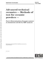
This standard covers the fuel cell power system as defined in 3.8 and Figure 1.
1.6
This standard applies to d.c. type fuel cell power systems, with a rated output voltage
not exceeding 150 V d.c. for indoor and outdoor use.
1.7
This standard covers fuel cell power systems whose fuel source container is
permanently attached to either the industrial truck or the fuel cell power system.
1.8
The following are not included in the scope of this standard:
–
detachable type fuel source containers;
–
hybrid trucks that include an internal combustion engine;
–
reformer-equipped fuel cell power systems;
–
fuel cell power systems intended for operation in potentially explosive atmospheres;
–
fuel storage systems using liquid hydrogen.
BS EN 62282-4-101:2014
IEC 62282-4-101:2014 © IEC 2014
Fuel (hydrogen, methanol)
–9–
Coolant
System boundary
Excess/released fuel
Fuel storage
(hydrogen,
methanol)
Oxidant (air)
Ventilation air
Fuel
regulating &
piping
system
Ventilation
system
Water
EMD
Vibration,
wind, rain,
temperature.
Thermal
management
Conditioner
and
processing
system
Fuel cell
module
(stack)
Waste heat
Internal power needs
Power
conditioning
Electrical
power output
Energy
storage
Exhaust gases
Water
treatment and
containment
Control
system
Discharge water
(liquid or gaseous)
EMI
Noise,
vibration
IEC
Key
EMD
electromagnetic disturbance.
EMI
electromagnetic interference.
NOTE
A fuel cell power system may contain all or some of the above components.
Figure 1 – Fuel cell power systems for industrial trucks
2
Normative references
The following documents, in whole or in part, are normatively referenced in this document and
are indispensable for its application. For dated references, only the edition cited applies. For
undated references, the latest edition of the referenced document (including any
amendments) applies.
IEC 60079-0, Explosive atmospheres – Part 0: Equipment – General requirements
IEC 60079-10-1, Explosive atmospheres – Part 10-1: Classification of areas – Explosive gas
atmospheres
IEC 60079-29-1, Explosive atmospheres – Part 29-1: Gas detectors – Performance
requirements of detectors for flammable gases
IEC 60079-29-4, Explosive atmospheres – Part 29-4: Gas detectors – Performance
requirements of open path detectors for flammable gases
IEC 60204-1, Safety of machinery – Electrical equipment of machines – Part 1: General
requirements
IEC 60227-3, Polyvinyl chloride insulated cables of rated voltages up to and including
450/750 V – Part 3: Non-sheathed cables for fixed wiring
IEC 60227-5, Polyvinyl chloride insulated cables of rated voltages up to and including
450/750 V – Part 5: Flexible cables (cords)
– 10 –
BS EN 62282-4-101:2014
IEC 62282-4-101:2014 © IEC 2014
IEC 60335-2-41, Household and similar electrical appliances – Safety – Part 2-41: Particular
requirements for pumps
IEC 60335-2-80, Household and similar electrical appliances – Safety – Part 2-80: Particular
requirements for fans
IEC 60364-4-41:2005, Low-voltage electrical installations – Part 4-41: Protection for safety –
Protection against electric shock
IEC 60529, Degrees of protection provided by enclosures (IP Code)
IEC 60584-1, Thermocouples – Part 1: Reference tables
IEC 60664-1, Insulation coordination for equipment within low-voltage systems – Part 1:
Principles, requirements and tests
IEC 60695 (all parts), Fire hazard testing
IEC 60695-1-30, Fire hazard testing – Part 1-30: Guidance for assessing the fire hazard of
electrotechnical products – Preselection testing process – General guidelines
IEC 60695-10-2, Fire hazard testing – Part 10-2: Abnormal heat – Ball pressure test
IEC 60695-11-4, Fire hazard testing – Part 11-4: Test flames – 50 W flame – Apparatus and
confirmational test method
IEC 60695-11-10, Fire hazard testing – Part 11-10: Test flames – 50 W horizontal and vertical
flame test methods
IEC 60730-1:2013, Automatic electrical controls for household and similar use – Part 1:
General requirements
IEC 60730-2-17, Automatic electrical controls for household and similar use – Part 2-17:
Particular requirements for electrically operated gas valves, including mechanical
requirements
IEC 60947-3, Low-voltage switchgear and controlgear – Part 3: Switches, disconnectors,
switch-disconnectors and fuse-combination untis
IEC 60947-5-1, Low-voltage switchgear and controlgear – Part 5-1: Control circuit devices
and switching elements – Electromechanical control circuit devices
IEC 60950-1:2005, Information technology equipment – Safety – Part 1: General requirements
IEC 61204-7, Low-voltage power supplies, d.c. output – Part 7: Safety requirements
IEC TS 61430, Secondary cells and batteries – Test methods for checking the performance of
devices designed for reducing explosion hazards – Lead-acid starter batteries
IEC 61558-1, Safety os power transformers, power supplies, reactors and similar products –
Part 1: General requirements and tests
IEC 62103, Electronic equipment for use in power installations
BS EN 62282-4-101:2014
IEC 62282-4-101:2014 © IEC 2014
– 11 –
IEC 62133, Secondary cells and batteries containing alkaline or other non-acid electrolytes –
Safety requirements for portable sealed secondary cells, and for batteries made from them,
for use in portable applications
IEC 62282-2, Fuel cell technologies – Part 2: Fuel cell modules
ISO 179 (all parts), Plastics – Determination of Charpy impact properties
ISO 180, Plastics – Determination of Izod impact strength
ISO 877 (all parts), Plastics – Methods of exposure to solar radiation
ISO 1419, Rubber- or plastics-coated fabrics – Accelerated-ageing tests
ISO 1421, Rubber- or plastics-coated fabrics – Determination of tensile strength and
elongation at break
ISO 1798, Flexible cellular polymeric materials – Determination of tensile strength and
elongation at break
ISO 2440, Flexible and rigid cellular polymeric materials – Accelerated ageing tests
ISO 2626, Copper – Hydrogen embrittlement test
ISO 3691-1, Industrial trucks – Safety requirements and verification – Part 1: Self-propelled
industrial trucks, other than driverless trucks, variable-reach trucks and burden-carrier trucks
ISO 3691-7, Industrial trucks – Safety requirements and verification – Part 7: Regional
requirements for countries within the European Community
ISO 3691-8, Industrial trucks – Safety requirements and verification – Part 8: Regional
requirements for countries outside the European Community
ISO 3864-1, Graphical symbols – Safety colours and safety signs – Part 1: Design principles
for safety signs and safety markings
ISO 3996, Road Vehicles – Brake hose assemblies for hydraulic braking systems used with a
non-petroleum-base brake fluid
ISO 4038, Road vehicles – Hydraulic braking systems – Simple flare pipes, tapped holes,
male fittings and hose end fittings
ISO 4080, Rubber and plastics hoses and hose assemblies – Determination of permeability to
gas
ISO 4675, Rubber- or plastics-coated fabrics – Low-temperature bend test
ISO 7010, Graphical symbols – Safety colours and safety signs – Registered safety signs
ISO 7866:2012, Gas cylinders – Refillable seamless aluminum alloy gas cylinders – Design,
construction and testing
ISO 9809-1, Gas cylinders – Refillable seamless steel gas cylinders – Design, construction
and testing – Part 1: Quenched and tempered steel cylinders with tensile strength less than
1 100 MPa
– 12 –
BS EN 62282-4-101:2014
IEC 62282-4-101:2014 © IEC 2014
ISO 10380, Pipework – Corrugated metal hoses and hose assemblies
ISO 10442, Petroleum, chemical and gas service industries – Packaged, integrally geared
centrifugal air compressors
ISO 10806, Pipework – Fittings for corrugated metal hoses
ISO 11114-4, Transportable gas cylinders – Compatibility of cylinder and valve materials with
gas contents – Part 4: Test methods for selecting metallic materials resistant to hydrogen
embrittlement
ISO 13226, Rubber – Standard reference elastomers (SREs) for characterizing the effect of
liquids on vulcanized rubbers
ISO 13849-1, Safety of machinery – Safety-related parts of control systems – Part 1: General
principles for design
ISO 14113, Gas welding equipment – Rubber and plastic hose and hose assemblies for use
with industrial gases up to 450 bar
ISO/TS 14687-2, Hydrogen fuel – Product specification – Part 2: Proton exchange membrane
(PEM) fuel cell applications for road vehicles
ISO 15500-12, Road vehicles – Compressed natural gas (CNG) fuel system components –
Part 12: Pressure relief valve (PRV)
ISO 15649, Petroleum and natural gas industries – Piping
ISO/TS 15869:2009, Gaseous hydrogen and hydrogen blends – Land vehicle fuel tanks
ISO 15916, Basic considerations for the safety of hydrogen systems
ISO 16010, Elastomeric seals – Material requirements for seals used in pipes and fittings
carrying gaseous fuels and hydrocarbon fluids
ISO 16111:2008, Transportable gas storage devices – Hydrogen absorbed in reversible metal
hydride
ISO 17268, Compressed hydrogen surface vehicle refuelling connection devices
ISO 21927-3, Smoke and heat control systems – Part 3: Specification for powered smoke and
heat exhaust ventilators
ISO 23551-1, Safety and control devices for gas burners and gas-burning appliances –
Particular requirements – Part 1: Automatic valves
3
Terms and definitions
For the purposes of this document, the following terms and definitions apply.
3.1
abnormal operation
operation of the fuel cell power system with any one electrical or control component
malfunction or failure, in any failure mode regarded as reasonably probable in the FMEA; but
BS EN 62282-4-101:2014
IEC 62282-4-101:2014 © IEC 2014
– 13 –
excluding accidental rupture or breakdown of the containers of flammable liquids, vapours
and/or gases
3.2
bonding
permanent joining of metallic parts to form a positive electrically conductive path that provides
electrical continuity between non-current carrying metal parts and is capable of conducting
any fault current that may occur
Note 1 to entry: This applies to bonding within the fuel cell power system and between the fuel cell power system
and truck and does not refer to the means to ground the truck itself, such as with a grounding strap or with tyres.
Acceptable methods of bonding shall be by any positive means, such as by a clamp, rivet, bolt, screw, welded joint,
soldered or brazed joint, or a bonding jumper with a closed loop connector secured by a screw.
3.3
check-valve
fluid control device that allows fluids to flow in only one direction
3.4
circuit, limited power
circuit involving a potential greater than 42,4 V peak (30 V r.m.s.) or 60 V d.c and power after
60 s of operation comply with the values outlined in Tables 2B and 2C of IEC 60950-1:2005
Note 1 to entry: A circuit that is low voltage under both normal and single fault conditions is referred to in
IEC 60950-1 as a safety extra low voltage (SELV).
3.5
low-voltage circuit
circuit involving a peak open-circuit potential of not more than 42,4 V (30 V r.m.s.) or 60 V d.c.
supplied by a battery, a fuel cell, a transformer having a maximum volt-ampere (VA), rating of
less than 100 VA and a maximum secondary output of 30 V a.c. or by a combination of a
transformer and a fixed impedance that as a system, complies with IEC 61558-1
Note 1 to entry: A circuit derived by connecting a resistance in series with a voltage supply circuit as a means of
limiting the voltage and current, is not considered to be a low-voltage circuit.
3.6
dilution boundary
extent of a flammable area or zone created by a limited release of flammable gas or vapour,
internal to the fuel cell power system or truck in which it is mounted, and controlled by
mechanical ventilation or other effective means
Note 1 to entry:
This is outlined in IEC 60079-10.
3.7
electrostatic discharge
ESD
discharge created by static electricity
3.8
fuel cell power system
generator system that uses one or more fuel cell module(s) to generate electric power and
heat
Note 1 to entry: See Figure 1 for a block diagram of a fuel cell power system. A fuel cell power system may
contain all or some of the components shown in Figure 1. The fuel cell power system for use with industrial trucks
will be in one of the forms as outlined in 3.9 and 3.10.
[SOURCE: IEC TS 62282-1:2013, 3.49, modified – Addition of second sentence to the Note to
entry]
– 14 –
BS EN 62282-4-101:2014
IEC 62282-4-101:2014 © IEC 2014
3.9
self-contained system
complete system incorporated into its own housing that is intended to replace or combine with
a battery system to power an industrial truck
Note 1 to entry: Display and control functions may be located outside the system's housing in proximity to the
operator's compartment. However, if counterweight is required outside the system’s housing or direct
communication is required between the system and the truck controller, then it will be considered an integrated
system (see 3.10).
3.10
integrated fuel cell power system
complete system of fuel cell components and parts that are incorporated into the industrial
truck with the various parts of the system potentially distributed throughout the truck
3.11
hazardous (classified) areas
any work area or space where combustible dust, ignitable fibres, or flammable, volatile liquids,
gases, vapours or mixtures are or may be present in the air in quantities sufficient to produce
explosive or ignitable mixtures as defined by IEC 60079-10-1
3.12
integral
something that is either contained within the fuel cell power system or is external, but is a part
of the fuel cell power system
3.13
lower flammability limit
LFL
minimum concentration of fuel in a fuel-air mixture where a combustion can be ignited by an
ignition source
Note 1 to entry: A fuel-air mixture is flammable when combustion can be started by an ignition source. The main
component concerns the proportions or composition of the fuel-air mixture. A mixture that has less than a critical
amount of fuel, known as the lower flammability limit (LFL) or more than a critical amount of fuel, known as the rich
or upper flammability limit (UFL), will not be flammable.
3.14
maximum allowable working pressure
MAWP
maximum gauge pressure at which a fuel cell or fuel cell power system may be operated
Note 1 to entry:
See Annex A for a comparison table of pressure terms.
Note 2 to entry:
The maximum allowable working pressure is expressed in Pa.
Note 3 to entry: The maximum allowable working pressure is the pressure used in determining the setting of
pressure limiting/relieving devices installed to protect a component or system from accidental over-pressuring.
[SOURCE: IEC TS 62282-1:2013, 3.86.3, modified – Addition of new Note 1 to entry]
3.15
maximum continuous load rating
maximum continuous power that can be sustained by the fuel cell power system independent
of any electrical energy storage device or storage component at 25 °C and ambient pressure
0,1 MPa
3.16
maximum operating pressure
MOP
highest gauge pressure of a component or the system that is expected during normal
operation
BS EN 62282-4-101:2014
IEC 62282-4-101:2014 © IEC 2014
Note 1 to entry:
– 15 –
See Annex A for a comparison table of pressure terms.
3.17
normal release
limited internal localized volumes of flammable vapour concentrations released during normal
operation that may include fuel cell purge
3.18
normal operation
all operating and non-operating modes encountered during product use that are not the result
of a failure
3.19
pressure relief device
PRD
pressure and/or temperature activated device used to prevent the pressure from rising above
a predetermined maximum and thereby prevent failure of a pressurized part or system
3.20
thermally activated pressure relief device
TPRD
pressure relief device that activated thermally
3.21
safety control
automatic controls and interlocks including relays, switches, sensors and other auxiliary
equipment used in conjunction therewith to form a safety control system, which is intended to
prevent unsafe operation of the controlled equipment
3.22
safety critical component
component, device, circuit, software or similar part whose failure would affect the safety of the
fuel cell power system as determined in 4.15
3.23
service pressure
nominal working pressure
pressure, as specified by the manufacturer, at a uniform gas temperature of 15 °C and full gas
content
Note 1 to entry:
This term only relates to the hydrogen pressure vessel.
Note 2 to entry:
See Annex A for a comparison table of pressure terms.
3.24
gas purge
protective operation to remove gases and/or liquids, such as fuel, hydrogen, air or water, from
a fuel cell power system
[SOURCE: IEC TS 62282-1:2013, 3.60]
3.25
touch current
electric current through a human body or an animal body when it touches one or more
accessible parts
3.26
zone system of classification
means for classifying areas within the fuel cell power system using the methods outlined in
IEC 60079-10-1
– 16 –
Note 1 to entry:
BS EN 62282-4-101:2014
IEC 62282-4-101:2014 © IEC 2014
The potential zones of this system are as follows:
Group II, zone 0 – A location in which ignitable concentrations of flammable gases or vapours are present for long
periods of time (e.g. inside the fuel cell stack or other hydrogen carrying components).
Group II, zone 1 – A location:
a)
in which ignitable concentrations of flammable gases or vapours are likely to exist under normal operating
conditions; or
b)
in which ignitable concentrations of flammable gases or vapours may exist frequently because of repair or
maintenance operations or because of leakage; or
c)
in which equipment is operated or processes are carried on of such a nature that equipment breakdown or
fault operations could result in the release of ignitable concentrations of flammable gases or vapours and also
cause simultaneous failure of electrical equipment in a mode to cause the electrical equipment to become a
source of ignition; or
d)
that is adjacent to a Group II, zone 0 location from which ignitable concentrations of vapours could be
communicated, unless communication is prevented by adequate positive pressure ventilation from a source of
clean air and effective safeguards against ventilation failure are provided (e.g. space in which purge gases are
immediately released to be diluted or areas immediately adjacent to the fuel cell stack and hydrogen
recirculation system).
Group II, zone 2 – A location:
a)
in which ignitable concentrations of flammable gases or vapours are not likely to occur in normal operation and
if they do occur, will exist only for a short period; or
b)
in which volatile flammable liquids, flammable gases or flammable vapours are handled, processed, or used,
but in which the liquids, gases or vapours normally are confined within closed containers of closed systems
from which then can escape only as a result of accidental rupture or breakdown of the containers or system or
as a result of abnormal operation of the equipment with which the liquids or gases are handled, processed, or
used; or
c)
in which ignitable concentrations of flammable gases or vapours normally are prevented by positive
mechanical ventilation, but which may become hazardous as result of failure or abnormal operation of the
ventilation equipment; or
d)
that is adjacent to a group II, zone 1 location from which ignitable concentrations of flammable gases or
vapours could be communicated, unless such communication is prevented by adequate positive-pressure
ventilation from a source of clean air and effective safeguards against ventilation failure are provided (e.g. an
area with a hydrogen fuel line and fittings at bulkhead locations but without components – a pass through).
Unclassified zone – A location:
a)
in an area where there is no risk of ignitable concentrations of flammable gases; or
b)
where flammable gases are not present as part of the standard processes; or
c)
where there are no fittings that may leak; or
d)
that is adjacent only to other unclassified zones or zone 2 locations (e.g. a compartment with a fuel line
passing through without bulkhead connections or other fittings adjacent only to zone 2 locations and areas
outside of the systems).
4
Construction requirements for safety
4.1
General
4.1.1
Any component of a product covered by this standard shall comply with the
requirements for that component. Normative references for standards covering components
used in the products covered by this standard is given in Clause 2.
4.1.2
A component is not required to comply with a specific requirement of the normative
referenced standards that:
a) involves a feature or characteristic not required in the application of the component in the
product covered by this standard, or
b) is superseded by a requirement in this standard.
BS EN 62282-4-101:2014
IEC 62282-4-101:2014 © IEC 2014
– 17 –
4.1.3
Any component shall be used in accordance with its rating established for the
intended conditions of use.
4.1.4
Specific components are incomplete in construction features or restricted in
performance capabilities. Such components are intended for use only under limited conditions,
such as certain temperatures not exceeding specified limits, and shall be used only under
those specific conditions.
4.2
Hydrogen and other fluid containing parts
4.2.1
General
4.2.1.1
Pressure or fluid containing parts shall be resistant to the action of the fluid.
4.2.1.2
The refuelling interface for hydrogen system shall be in accordance with ISO 17268.
4.2.1.3 Metallic parts containing hydrogen gas shall be resistant to hydrogen embrittlement
as outlined in ISO 15916. If employing a material other than as outlined in ISO 15916, an
evaluation for susceptibility to hydrogen embrittlement will need to be conducted in
accordance with ISO 11114-4 or ISO 2626.
4.2.1.4 Where atmospheric corrosion of a part containing fluid interferes with its intended
function, or permits external leakage of a fluid creating a hazardous condition, the part shall
be made of corrosion-resistant material or is to be provided with a corrosion-resistant
protective coating.
4.2.1.5 Any elastomeric parts, relied upon for safety such as a seal for fluids other than
hydrogen, which could create a hazard when leaked (for example, a gasket between electrical
and wetted parts), shall be suitable for the application as determined by ISO 1419, ISO 1421,
ISO 13226, ISO 16010 and ISO 4675, as applicable.
4.2.1.6 Any elastomeric parts employed as a seal for hydrogen shall be suitable for use with
hydrogen. The elastomeric materials outlined in ISO 15916, shall be considered for reference
and guidance. The material shall be evaluated for tensile strength and elongation as-received
and after oven-aging (based on service temperatures) in accordance with 5.21.
4.2.2
Piping, hoses, tubing and fittings
4.2.2.1 Where conveying gases or vapours at pressures exceeding 103,4 kPa gauge, or
liquids at pressures exceeding 1 103 kPa, or temperatures exceeding 120 °C, piping and
associated component parts shall be designed, fabricated and tested to conform to all
applicable specifications of ISO 15649.
4.2.2.2 Piping utilized at levels below the pressures and/or temperatures noted in 4.2.2.1
and nonmetallic piping shall be evaluated to the requirements of this standard with
consideration given to materials and fluids contained and service conditions, including
pressures and temperatures. Non-metallic piping containing gaseous hydrogen or methanol
fuel shall be designed, fabricated and tested to the additional requirements in 4.2.2.6.
4.2.2.3 Non-metallic hoses used for gaseous hydrogen or methanol fuels located external to
the fuel cell power system and subject to physical stress shall meet the hydrostatic testing,
adhesion (rubber only), flexibility, low-temperature flexibility, ozone resistance (for hoses with
an outer protective cover of rubber), UV resistance (for hoses with plastic cover), permeability
to gas, electrical conductivity, and end fitting integrity tests of ISO 14113, Materials shall be
suitable for service with hydrogen fuel, or the fluid contained (i.e. methanol), in accordance
with items in 4.2.1. Flexible hose longer than 1,5 m shall have a stainless steel wire braid
reinforcement.
– 18 –
BS EN 62282-4-101:2014
IEC 62282-4-101:2014 © IEC 2014
4.2.2.4 Flexible metal connectors and associated fittings, when used for conveying gaseous
hydrogen, shall comply with ISO 10806, and ISO 10380, as required.
4.2.2.5 A hydrogen fuel line shall be supported to minimize chafing and to maintain at least
a 51 mm clearance from exhaust- and electrical-system parts.
4.2.2.6
Non-metallic hydrogen and methanol fuel lines shall:
–
be protected within ventilated enclosures where they will be subject to a minimum of
mechanical or physical stresses;
–
be conductive to avoid static discharge. Compliance is determined by the continuity test of
2) of 5.9 for metal, and 3) of 5.9, for nonmetallic;
–
employ materials that have been evaluated and found suitable for fluids they contain with
consideration given to temperatures they are exposed to during service. Compliance shall
be determined by 5.21 and 5.22, as applicable; and
–
comply with the ESD requirements for ISO 3996 or ISO 4038 when connected between the
fuel system and the stack.
4.2.2.7 Pipe, tubing, fittings, and other piping components shall be capable of withstanding a
minimum hydrostatic test of 1,5 times the rated service pressure without structural failure.
Exception: high-pressure pipe, tubing, fittings, and other piping components shall have a
safety margin equivalent to the storage cylinder in use. See 4.2.3.
4.2.3
Hydrogen pressure vessels
4.2.3.1 Pressure vessels shall be specifically designed for the service conditions of the
industrial truck application that includes the maximum number of fill cycles expected, the
ranges of pressures and temperatures expected during operation and filling, the effect of
hydrogen on fatigue life and the frequency of inspection.
4.2.3.2 With reference to 4.2.3.1, a pressure vessel shall be designed, manufactured, and
tested with the following conditions and limitations:
a) For Type 1 steel tanks, it shall be designed in accordance with ISO 9809-1.
b) The term "working pressure" of the container as defined in ISO/TS 15869 is identical to
"service pressure" in this standard and shall be either 25 MPa, 35 MPa or 70 MPa gauge
only.
c) The cylinder shall be designed for not less than 11 250 full fill cycles, which represents a
10-year life. ISO/TS 15869:2009, 4.5, 11 k) and 11 l), and Annex A do not apply.
NOTE
11 250 full fill cycles, i.e. 3 refills/day, 365 days/years, 10 years = 10 950 cycles.
d) ISO/TS 15869:2009, 9.5, and Annex E, covering alternate type tests, shall not apply.
e) ISO/TS 15869:2009, 9.2.2, shall not apply. However, stainless steels; SUS316L, AISI316L,
and AISI316; having >12 % nickel composition and <0,1 % magnetic phases by volume
are exempt from hydrogen compatibility tests in Clause B.2 of ISO/TS 15869:2009. The
fabrication process using these materials shall not include welds.
f)
In 9.2.3 of ISO/TS 15869:2009 the exemption for aluminum alloys that conform to 6.1 and
6.2 of ISO 7866:2012, shall not apply. However, aluminum alloys: A6061-T6, A6061-T62,
A6061-T651 and A6061-T6511 are exempt from hydrogen compatibility tests in Clause
B.2 of ISO/TS 15869:2009. The fabrication process using these aluminum materials shall
not include welds.
g) Other than indicated in d) or e), hydrogen compatibility of metallic materials in contact
with hydrogen gas shall be demonstrated by fulfilling the requirements of Clause B.2,
point b) or c) of ISO/TS 15869:2009 by using hydrogen that meets the requirements of
ISO/TS 14687-2 and with the additional requirements that the oxygen limit be changed to
less than 1 µmol per mol and the water limit shall be changed to less than 3 µmol per mol.
BS EN 62282-4-101:2014
IEC 62282-4-101:2014 © IEC 2014
– 19 –
h) If fatigue testing is conducted in accordance with point c) of Clause B.2 of ISO/TS
15869:2009, it shall be done using hydrogen quality as specified in f) above, and at a rate
not exceeding 10 cycles per minute. The sample vessel shall be pressure cycled until
failure or to a minimum of 3 times the full fill cycles specified in c) above. The sample
vessel is allowed to fail by leakage and not rupture at a number of cycles greater than the
number of full fill cycles specified in c) above. If the sample vessel achieves 3 times the
number of full fill cycles specified in c) above without failure, the ambient temperature
pressure cycling test, specified in Clause B.7 of ISO/TS 15869:2009, and the leak-beforebreak (LBB) test in Clause B.8 of ISO/TS 15869:2009 is not needed.
i)
With regards to h) above, leakage is the escape of gas from a vessel that is not attributed
to leakage at a fitting connection or to permeation, and which is not caused by rupture.
Escape of gas from a crack would be considered leakage and not rupture. Rupture is a
violent breach of the vessel sidewall, head or bottom.
j)
Clause B.2, point a) of ISO/TS 15869:2009 shall not apply.
4.2.3.3 A pressure vessel and fill fitting shall be placed within the plan view outline of the
industrial truck or placed in an enclosure as defined in 4.12 and located to minimize the
possibility of damage to the vessel or hydrogen-related fittings.
4.2.3.4 An excess-flow and check-valve, if present, shall be directly connected to the
pressure vessel or mounted in line with the pressure vessel, where there is no shut-off device
in between the pressure vessel and the check valve, so as to minimize the negative effects of
shock, vibration and accidental damage.
4.2.3.5 The refuelling line shall be fitted with a check valve redundant to the check valve in
the receptacle given in ISO 17268.
4.2.3.6 Pressure vessels shall have a provision for being de-fuelled (de-pressurized) and
purged of hydrogen using an inert gas as outlined in the operating instructions or the
maintenance manual, as applicable, provided with the fuel cell power system.
4.2.3.7 A manual valve to isolate the fuel supply shall be located near the pressure vessel
so that the fuel supply to the fuel power system can be shut off for maintenance or long-term
storage.
4.2.3.8 The hydrogen pressure vessel shall be permanently mounted to the fuel cell power
system module or to the industrial truck to ensure the pressure vessel does not become
dislodged while in use and is not removable for refuelling.
4.2.4
Metal hydride container
Fuel storage systems using hydrogen stored in metal hydrides shall comply with Clauses 4, 5,
and 6 of ISO 16111:2008.
4.2.5
Methanol fuel tank
4.2.5.1 Methanol fuel tanks shall be constructed of suitable materials in accordance with
4.2.1 and 4.2.2 shall meet the requirements as noted below. Such vessels, and their related
joints and fittings, shall be designed and constructed with adequate strength for functionality
and leakage resistance to prevent unintended releases.
4.2.5.2 Methanol fuel tanks shall be specifically designed for the service conditions of the
industrial truck application that includes the ranges of pressures and temperatures expected
during operation and filling, the effect of methanol on fatigue life of the tank, and the
frequency of inspection.