Bsi bs en 62137 4 2014
Bạn đang xem bản rút gọn của tài liệu. Xem và tải ngay bản đầy đủ của tài liệu tại đây (2.27 MB, 48 trang )
BS EN 62137-4:2014
Incorporating corrigendum February 2015
BSI Standards Publication
Electronics assembly
technology
Part 4: Endurance test methods for
solder joint of area array type package
surface mount devices
BRITISH STANDARD
BS EN 62137-4:2014
National foreword
This British Standard is the UK implementation of EN 62137-4:2014,
incorporating corrigendum February 2015. It is identical to
IEC 62137-4:2014. It supersedes BS EN 62137:2004, which is withdrawn.
The UK participation in its preparation was entrusted to Technical
Committee EPL/501, Electronic Assembly Technology.
A list of organizations represented on this committee can be obtained on
request to its secretary.
This publication does not purport to include all the necessary provisions of
a contract. Users are responsible for its correct application.
© The British Standards Institution 2015.
Published by BSI Standards Limited 2015
ISBN 978 0 580 89842 6
ICS 31.190
Compliance with a British Standard cannot confer immunity from
legal obligations.
This British Standard was published under the authority of the
Standards Policy and Strategy Committee on 28 February 2015.
Amendments/corrigenda issued since publication
Date
Text affected
30 June 2015
Implementation of CENELEC corrigendum
February 2015. Supersession information added
to National Foreword, EN title page and EN Foreword.
EUROPEAN STANDARD
EN 62137- 4
NORME EUROPÉENNE
EUROPÄISCHE NORM
December 2014
ICS 31.190
Incorporating corrigendum February 2015
Supersedes EN 62137:2004
English Version
Electronics assembly technology Part 4: Endurance test methods for solder joint of area array type
package surface mount devices
(IEC 62137-4:2014)
Technique d'assemblage des composants électroniques Partie 4: Méthodes d'essais d'endurance des joints brasés
des composants pour montage en surface à btiers de
type matriciel
(CEI 62137-4:2014)
Montageverfahren für elektronische Baugruppen Teil 4: Oberflächenmontierbare Bauteilgehäuse mit
Flächenmatrix - (Lebens-)Dauerprüfungen für
Lötverbindungen
(IEC 62137-4:2014)
This European Standard was approved by CENELEC on 2014-11-13. CENELEC members are bound to comply with the CEN/CENELEC
Internal Regulations which stipulate the conditions for giving this European Standard the status of a national standard without any alteration.
Up-to-date lists and bibliographical references concerning such national standards may be obtained on application to the CEN-CENELEC
Management Centre or to any CENELEC member.
This European Standard exists in three official versions (English, French, German). A version in any other language made by translation
under the responsibility of a CENELEC member into its own language and notified to the CEN-CENELEC Management Centre has the
same status as the official versions.
CENELEC members are the national electrotechnical committees of Austria, Belgium, Bulgaria, Croatia, Cyprus, the Czech Republic,
Denmark, Estonia, Finland, Former Yugoslav Republic of Macedonia, France, Germany, Greece, Hungary, Iceland, Ireland, Italy, Latvia,
Lithuania, Luxembourg, Malta, the Netherlands, Norway, Poland, Portugal, Romania, Slovakia, Slovenia, Spain, Sweden, Switzerland,
Turkey and the United Kingdom.
European Committee for Electrotechnical Standardization
Comité Européen de Normalisation Electrotechnique
Europäisches Komitee für Elektrotechnische Normung
CEN-CENELEC Management Centre: Avenue Marnix 17, B-1000 Brussels
© 2014 CENELEC All rights of exploitation in any form and by any means reserved worldwide for CENELEC Members.
Ref. No. EN 62137-4:2014 E
BS EN 62137-4:2014
EN 62137-4:2014
-2-
Foreword
The text of document 91/1188/FDIS, future edition 1 of IEC 62137-4, prepared by
IEC/TC 91 "Electronics assembly technology" was submitted to the IEC-CENELEC parallel vote and
approved by CENELEC as EN 62137-4:2014.
The following dates are fixed:
•
latest date by which the document has to be
implemented at national level by
publication of an identical national
standard or by endorsement
(dop)
2015-08-13
•
latest date by which the national
standards conflicting with the
document have to be withdrawn
(dow)
2017-11-13
Attention is drawn to the possibility that some of the elements of this document may be the subject of
patent rights. CENELEC [and/or CEN] shall not be held responsible for identifying any or all such
patent rights.
This document supersedes EN 62137:2004.
Endorsement notice
The text of the International Standard IEC 62137-4:2014 was approved by CENELEC as a European
Standard without any modification.
In the official version, for Bibliography, the following notes have to be added for the standards indicated:
1)
IEC 60068-1:1988+A1:1992 NOTE
Harmonized as EN 60068-1:1994 (not modified).
IEC 60068-2-2
NOTE
Harmonized as EN 60068-2-2.
IEC 60068-2-6
NOTE
Harmonized as EN 60068-2-6.
IEC 60068-2-21:2006
NOTE
Harmonized as EN 60068-2-21:2006 (not modified).
IEC 60068-2-27
NOTE
Harmonized as EN 60068-2-27.
IEC 60068-2-44:1995
NOTE
Harmonized as EN 60068-2-44:1995 (not modified).
IEC 60068-2-58:2004
NOTE
Harmonized as EN 60068-2-58:2004 (not modified).
IEC 60068-2-78:2001
NOTE
Harmonized as EN 60068-2-78:2001 (not modified).
IEC 60749-1:2002
NOTE
Harmonized as EN 60749-1:2003 (not modified).
IEC 60749-20:2008
NOTE
Harmonized as EN 60749-20:2009 (not modified).
IEC 60749-20-1:2009
NOTE
Harmonized as EN 60749-20-1:2009 (not modified).
IEC 61188-5-8
NOTE
Harmonized as EN 61188-5-8.
IEC 61189-3:2007
NOTE
Harmonized as EN 61189-3:2008 (not modified).
IEC 61189-5
NOTE
Harmonized as EN 61189-5.
IEC 61190-1-1
NOTE
Harmonized as EN 61190-1-1.
IEC 61190-1-2
NOTE
Harmonized as EN 61190-1-2.
IEC 61760-1:2006
NOTE
Harmonized as EN 61760-1:2006 (not modified).
IEC 62137-1-3
NOTE
Harmonized as EN 62137-1-3.
IEC 62137-1-4:2009
NOTE
Harmonized as EN 62137-1-4:2009 (not modified).
1)
Superseded by EN 60068-2-78:2013 (IEC 60068-2-78:2012): DOW = 2015-12-03.
BS EN 62137-4:2014
EN 62137-4:2014
-3-
Annex ZA
(normative)
Normative references to international publications
with their corresponding European publications
The following documents, in whole or in part, are normatively referenced in this document and are
indispensable for its application. For dated references, only the edition cited applies. For undated
references, the latest edition of the referenced document (including any amendments) applies.
NOTE 1 When an International Publication has been modified by common modifications, indicated by (mod), the relevant
EN/HD applies.
NOTE 2 Up-to-date information on the latest versions of the European Standards listed in this annex is available here:
www.cenelec.eu
Publication
Year
Title
EN/HD
Year
IEC 60068-2-14
-
Environmental testing Part 2-14: Tests - Test N: Change of
temperature
EN 60068-2-14
-
IEC 60191-6-2
-
Mechanical standardization of
EN 60191-6-2
semiconductor devices Part 6-2: General rules for the preparation
of outline drawings of surface mounted
semiconductor device packages - Design
guide for 1,50 mm, 1,27 mm and 1,00 mm
pitch ball and column terminal packages
-
IEC 60191-6-5
-
Mechanical standardization of
EN 60191-6-5
semiconductor devices Part 6-5: General rules for the preparation
of outline drawings of surface mounted
semiconductor device packages - Design
guide for fine-pitch ball grid array (FBGA)
-
IEC 60194
-
Printed board design, manufacture and
assembly - Terms and definitions
-
IEC 61190-1-3
-
Attachment materials for electronic
EN 61190-1-3
assembly Part 1-3: Requirements for electronic
grade solder alloys and fluxed and nonfluxed solid solders for electronic soldering
applications
-
IEC 61249-2-7
-
Materials for printed boards and other
interconnecting structures Part 2-7: Reinforced base materials, clad
and unclad - Epoxide woven E-glass
laminated sheet of defined flammability
(vertical burning test), copper-clad
EN 61249-2-7
-
IEC 61249-2-8
-
Materials for printed boards and other
EN 61249-2-8
interconnecting structures Part 2-8: Reinforced base materials, clad
and unclad - Modified brominated epoxide
woven fibreglass reinforced laminated
sheets of defined flammability (vertical
burning test), copper-clad
-
EN 60194
BS EN 62137-4:2014
EN 62137-4:2014
-4-
Publication
Year
Title
EN/HD
Year
IEC 62137-3
2011
Electronics assembly technology Part 3: Selection guidance of
environmental and endurance test
methods for solder joints
EN 62137-3
2012
–5–
BS EN 62137-4:2014
IEC 62137-4:2014 © IEC 2014
CONTENTS
1
Scope .............................................................................................................................. 9
2
Normative references ...................................................................................................... 9
3
Terms definitions and abbreviations .............................................................................. 10
3.1
Terms and definitions ............................................................................................ 10
3.2
Abbreviations ........................................................................................................ 10
4
General ......................................................................................................................... 10
5
Test apparatus and materials ........................................................................................ 11
5.1
Specimen .............................................................................................................. 11
5.2
Reflow soldering equipment .................................................................................. 11
5.3
Temperature cycling chamber ............................................................................... 11
5.4
Electrical resistance recorder ................................................................................ 11
5.5
Test substrate ....................................................................................................... 11
5.6
Solder paste ......................................................................................................... 12
6
Specimen preparation .................................................................................................... 12
7
Temperature cycling test ............................................................................................... 14
7.1
Pre-conditioning .................................................................................................... 14
7.2
Initial measurement .............................................................................................. 14
7.3
Test procedure ...................................................................................................... 14
7.4
End of test criteria................................................................................................. 16
7.5
Recovery .............................................................................................................. 16
7.6
Final measurement ............................................................................................... 16
8
Temperature cycling life ................................................................................................ 16
9
Items to be specified in the relevant product specification ............................................. 16
Annex A (informative) Acceleration of the temperature cycling test for solder joints ............. 18
A.1
A.2
A.3
A.4
Annex B
General ................................................................................................................. 18
Acceleration of the temperature cycling test for an Sn-Pb solder joint ................... 18
Temperature cycling life prediction method for an Sn-Ag-Cu solder joint ............... 19
Factor that affects the temperature cycling life of the solder joint .......................... 23
(informative) Electrical continuity test for solder joints of the package .................... 24
General ................................................................................................................. 24
Package and daisy chain circuit ............................................................................ 24
Mounting condition and materials .......................................................................... 24
Test method .......................................................................................................... 24
Temperature cycling test using the continuous electric resistance monitoring
system .................................................................................................................. 24
Annex C (informative) Reflow solderability test method for package and test substrate
land ...................................................................................................................................... 26
B.1
B.2
B.3
B.4
B.5
C.1
General ................................................................................................................. 26
C.2
Test equipment ..................................................................................................... 26
C.2.1
Test substrate................................................................................................ 26
C.2.2
Pre-conditioning oven .................................................................................... 26
C.2.3
Solder paste .................................................................................................. 26
C.2.4
Metal mask for screen printing ....................................................................... 26
C.2.5
Screen printing equipment ............................................................................. 26
BS EN 62137-4:2014
IEC 62137-4:2014 © IEC 2014
–6–
C.2.6
Package mounting equipment ........................................................................ 26
C.2.7
Reflow soldering equipment ........................................................................... 26
C.2.8
X-ray inspection equipment ........................................................................... 27
C.3
Standard mounting process .................................................................................. 27
C.3.1
Initial measurement ....................................................................................... 27
C.3.2
Pre-conditioning ............................................................................................ 27
C.3.3
Package mounting on test substrate .............................................................. 27
C.3.4
Recovery ....................................................................................................... 28
C.3.5
Final measurement ........................................................................................ 28
C.4
Examples of faulty soldering of area array type packages ..................................... 28
C.4.1
Repelled solder by contamination on the ball surface of the BGA
package ......................................................................................................... 28
C.4.2
Defective solder ball wetting caused by a crack in the package ..................... 28
C.5
Items to be given in the product specification ........................................................ 29
Annex D (informative) Test substrate design guideline ......................................................... 30
General ................................................................................................................. 30
D.1
D.2
Design standard .................................................................................................... 30
D.2.1
General ......................................................................................................... 30
D.2.2
Classification of substrate specifications ........................................................ 30
D.2.3
Material of the test substrate ......................................................................... 32
D.2.4
Configuration of layers of the test substrate ................................................... 32
D.2.5
Land shape of test substrate .......................................................................... 32
D.2.6
Land dimensions of the test substrate ............................................................ 32
D.3
Items to be given in the product specification ........................................................ 33
Annex E (informative) Heat resistance to reflow soldering for test substrate ........................ 34
General ................................................................................................................. 34
E.1
E.2
Test apparatus ...................................................................................................... 34
E.2.1
Pre-conditioning oven .................................................................................... 34
E.2.2
Reflow soldering equipment ........................................................................... 34
E.3
Test procedure ...................................................................................................... 34
E.3.1
General ......................................................................................................... 34
E.3.2
Pre-conditioning ............................................................................................ 34
E.3.3
Initial measurement ....................................................................................... 34
E.3.4
Moistening process (1) .................................................................................. 35
E.3.5
Reflow heating (1) ......................................................................................... 35
E.3.6
Moistening process (2) .................................................................................. 35
E.3.7
Reflow heating process (2) ............................................................................ 35
E.3.8
Final measurement ........................................................................................ 35
E.4
Items to be given in the product specification ........................................................ 35
Annex F (informative) Pull strength measurement method for the test substrate land .......... 36
General ................................................................................................................. 36
F.1
F.2
Test apparatus and materials ................................................................................ 36
F.2.1
Pull strength measuring equipment ................................................................ 36
F.2.2
Reflow soldering equipment ........................................................................... 36
F.2.3
Test substrate................................................................................................ 36
F.2.4
Solder ball ..................................................................................................... 36
F.2.5
Solder paste .................................................................................................. 36
F.2.6
Flux ............................................................................................................... 36
F.3
Measurement procedure ....................................................................................... 37
–7–
BS EN 62137-4:2014
IEC 62137-4:2014 © IEC 2014
F.3.1
Pre-conditioning ............................................................................................ 37
F.3.2
Solder paste printing ...................................................................................... 37
F.3.3
Solder ball placement .................................................................................... 37
F.3.4
Reflow heating process ................................................................................. 37
F.3.5
Pull strength measurement ............................................................................ 37
F.3.6
Final measurement ........................................................................................ 38
F.4
Items to be given in the product specification ........................................................ 38
Annex G (informative) Standard mounting process for the packages .................................... 39
General ................................................................................................................. 39
G.1
G.2
Test apparatus and materials ................................................................................ 39
G.2.1
Test substrate................................................................................................ 39
G.2.2
Solder paste .................................................................................................. 39
G.2.3
Metal mask for screen printing ....................................................................... 39
G.2.4
Screen printing equipment ............................................................................. 39
G.2.5
Package mounting equipment ........................................................................ 39
G.2.6
Reflow soldering equipment ........................................................................... 39
G.3
Standard mounting process .................................................................................. 40
G.3.1
Initial measurement ....................................................................................... 40
G.3.2
Solder paste printing ...................................................................................... 40
G.3.3
Package mounting ......................................................................................... 40
G.3.4
Reflow heating process ................................................................................. 40
G.3.5
Recovery ....................................................................................................... 41
G.3.6
Final measurement ........................................................................................ 41
G.4
Items to be given in the product specification ........................................................ 41
Annex H (informative) Mechanical stresses to the packages ................................................ 42
General ................................................................................................................. 42
H.1
H.2
Mechanical stresses ............................................................................................. 42
Bibliography .......................................................................................................................... 43
Figure 1 – Region for evaluation of the endurance test ......................................................... 11
Figure 2 – Typical reflow soldering profile for Sn63Pb37 solder alloy .................................... 13
Figure 3 – Typical reflow soldering profile for Sn96,5Ag3Cu,5 solder alloy ............................ 14
Figure 4 – Test conditions of temperature cycling test........................................................... 15
Figure A.1 – FBGA package device and FEA model for calculation of acceleration
factors AF ............................................................................................................................. 21
Figure A.2 – Example of acceleration factors AF with an FBGA package device using
Sn96,5Ag3Cu,5 solder alloy .................................................................................................. 22
Figure A.3 – Fatigue characteristics of Sn96,5Ag3Cu,5 an alloy micro solder joint
(N f = 20 % load drop from initial load) ................................................................................... 23
Figure B.1 – Example of a test circuit for the electrical continuity test of a solder joint ......... 24
Figure B.2 – Measurement example of continuously monitored resistance in the
temperature cycling test ........................................................................................................ 25
Figure C.1 – Temperature measurement of specimen using thermocouples .......................... 27
Figure C.2 – Repelled solder caused by contamination on the solder ball surface ................ 28
Figure C.3 – Defective soldering as a result of a solder ball drop .......................................... 29
Figure D.1 – Standard land shapes of the test substrate ....................................................... 32
Figure F.1 – Measuring methods for pull strength ................................................................. 37
BS EN 62137-4:2014
IEC 62137-4:2014 © IEC 2014
–8–
Figure G.1 – Example of printed conditions of solder paste ................................................... 40
Figure G.2 – Temperature measurement of the specimen using thermocouples .................... 41
Table 1 – Test conditions of temperature cycling test ............................................................ 15
Table A.1 – Example of test results of the acceleration factor (Sn63Pb37 solder alloy) ........ 19
Table A.2 – Example test results of the acceleration factor (Sn96,5Ag3Cu,5 solder
alloy) .................................................................................................................................... 21
Table A.3 – Material constant and inelastic strain range calculated by FEA for FBGA
package devices as shown in Figure A.1 (Sn96,5Ag3Cu,5 solder alloy) ................................ 22
Table D.1 – Types classification of the test substrate ............................................................ 31
Table D.2 – Standard layers' configuration of test substrates ................................................ 32
Table G.1 – Stencil design standard for packages ................................................................ 39
Table H.1 – Mechanical stresses to mounted area array type packages ................................ 4 2
–9–
BS EN 62137-4:2014
IEC 62137-4:2014 © IEC 2014
ELECTRONICS ASSEMBLY TECHNOLOGY –
Part 4: Endurance test methods for solder joint
of area array type package surface mount devices
1
Scope
This part of IEC 62137 specifies the test method for the solder joints of area array type
packages mounted on the printed wiring board to evaluate solder joint durability against
thermo-mechanical stress.
This part of IEC 62137 applies to the surface mounting semiconductor devices with area array
type packages (FBGA, BGA, FLGA and LGA) including peripheral termination type packages
(SON and QFN) that are intended to be used in industrial and consumer electrical or
electronic equipment.
An acceleration factor for the degradation of the solder joints of the packages by the
temperature cycling test due to the thermal stress when mounted, is described Annex A.
Annex H provides some explanations concerning various types of mechanical stress when
mounted.
The test method specified in this standard is not intended to evaluate semiconductor devices
themselves.
NOTE 1 Mounting conditions, printed wiring boards, soldering materials, and so on, significantly affect the result
of the test specified in this standard. Therefore, the test specified in this standard is not regarded as the one to be
used to guarantee the mounting reliability of the packages.
NOTE 2 The test method is not necessary, if there is no stress (mechanical or other) to solder joints in field use
and handling after mounting.
2
Normative references
The following documents, in whole or in part, are normatively referenced in this document and
are indispensable for its application. For dated references, only the edition cited applies. For
undated references, the latest edition of the referenced document (including any
amendments) applies.
IEC 60068-2-14,
Environmental testing – Part 2-14: Tests – Test N: Change of temperature
IEC 60191-6-2, Mechanical standardization of semiconductor devices – Part 6-2: General
rules for the preparation of outline drawings of surface mounted semiconductor device
packages – Design guide for 1,50 mm, 1,27 mm and 1,00 mm pitch ball and column terminal
packages
IEC 60191-6-5, Mechanical standardization of semiconductor devices – Part 6-5: General
rules for the preparation of outline drawings of surface mounted semiconductor device
packages – Design guide for fine-pitch ball grid array (FBGA)
IEC 60194,
Printed board design, manufacture and assembly – Terms and definitions
BS EN 62137-4:2014
IEC 62137-4:2014 © IEC 2014
– 10 –
IEC 61190-1-3, Attachment materials for electronic assembly – Part 1-3: Requirements for
electronic grade solder alloys and fluxed and non-fluxed solid solders for electronic soldering
applications
IEC 61249-2-7, Materials for printed boards and other interconnecting structures – Part 2-7:
Reinforced base materials clad and unclad – Epoxide woven E-glass laminated sheet of
defined flammability (vertical burning test), copper-clad
IEC 61249-2-8, Materials for printed boards and other interconnecting structures – Part 2-8:
Reinforced base materials clad and unclad – Modified brominated epoxide woven fibreglass
reinforced laminated sheets of defined flammability (vertical burning test), copper-clad
IEC 62137-3:2011, Electronics assembly technology – Part 3: Selection guidance of
environmental and endurance test methods for solder joints
3
Terms definitions and abbreviations
3.1
Terms and definitions
For the purposes of this document, the terms and definitions given in IEC 60191-6-2,
IEC 60191-6-5 and IEC 60194, as well as the following, apply.
3.1.1
temperature cycling life
period of time to reach a lost performance state as agreed between the trading partners
during the temperature cycling test
3.1.2
momentary interruption detector
instrument capable to detect an electrical discontinuity in the daisy chain circuits
Note 1 to entry:
3.2
See Annex B for the electrical continuity test of solder joint.
Abbreviations
FBGA
Fine-pitch ball grid array
BGA
Ball grid array
FLGA
Fine-pitch land grid array
LGA
Land grid array
SON
Small outline non-leaded package
QFN
Quad flat-pack non-leaded package
SMD
Surface mounting device
OSP
Organic solderability preservative
FR-4
Flame retardant type 4
FEA
Finite element method analysis
CGA
Column grid array
4
General
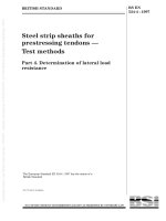
The regions of the solder joints to be evaluated are shown in Figure 1. The test method in this
standard is applicable to evaluate the durability of the solder joints against thermal stress to
the package mounted on substrate but not to test the mechanical strength of the package
itself.
BS EN 62137-4:2014
IEC 62137-4:2014 © IEC 2014
– 11 –
Therefore, the conditions for accelerated stress conditioning by a temperature cycling test
may exceed the maximum allowable temperature range for the package.
The test method specified in this standard is mainly applicable to the solder joint between
substrates of printed wiring board and the package as an evaluation target. However, the test
results depend on conditions such as the mounting method and the condition, materials and
the printed wiring board, etc. See Annex C to Annex G.
SMD (array type)
Device
Substrate
Solder
Substrate
Evaluation
area
Device
Substrate
Solder
Substrate
Device termination
Plating layers
Inter-metallic
compound layers
Substrate land
IEC
Figure 1 – Region for evaluation of the endurance test
5
Test apparatus and materials
5.1
Specimen
Specimen is the package mounted on the test substrate (refer to Clause 6 for preparation).
5.2
Reflow soldering equipment
The reflow soldering equipment shall be able to realize the reflow soldering temperature
profile specified in Clause 6. Examples of temperature profile are shown in Figure 2 and
Figure 3.
NOTE
A standard mounting process for the package is shown in Annex G.
5.3
Temperature cycling chamber
The temperature cycling chamber shall be able to realize the temperature cycling profile
specified in Figure 4. The general requirements for the temperature cycling chamber are
specified in IEC 60068-2-14.
5.4
Electrical resistance recorder
The electrical resistance recorder shall be able to detect electrical continuity interruption in
the daisy chain circuit. If there is no doubt of the measuring result, an electrical resistance
measuring instrument featured with a momentary interruption detector and/or a continuous
electrical resistance data logger should be used.
The interruption detector should be sufficiently sensitive to detect a 100 µs momentary
interruption. Furthermore, the electrical resistance measuring instrument should be able to
measure a resistance exceeding 1 000 Ω.
5.5
Test substrate
Unless otherwise specified in the product specification, the test substrate shall be as follows.
a) Test substrate material
BS EN 62137-4:2014
IEC 62137-4:2014 © IEC 2014
– 12 –
Test substrate material shall be a single sided printed wiring board for general use, for
example, copper-clad epoxide woven fiberglass reinforced laminated sheets as specified
in IEC 61249-2-7 or IEC 61249-2-8. The thickness shall be (1,6 ± 0,2) mm including
copper foil. The copper foil thickness shall be (35 ± 10) µm.
NOTE 1
Heat resistance to reflow soldering for the test substrate is described in Annex E.
b) Test substrate dimensions
The test substrate dimensions depend on the mounted package size and shape. However,
the test substrate dimensions shall be fixed on the pull strength test equipment.
c) Land shape and land dimensions
Land shape and land dimensions should be as specified in IEC 61188-5-8 or as
recommended by the package manufacturer.
Moreover, the test substrate and the test package shall be designed in such a way that
their land pattern forms a daisy chain circuit after mounting for the electrical continuity
measurement.
NOTE 2
Annex D provides a test substrate design guide.
NOTE 3 Annex C provides a solderability test for the substrate land. And Annex F provides a strength test for
the substrate land.
d) Surface finish of land pattern
If specified in the product specification, a solderable region (land pattern of the test
substrate) shall be treated suitably against oxidization, for example, by means of an
organic solderability preservative (OSP) layer. The surface protection shall not interfere
with the solderability of the land pattern being soldered by using the reflow soldering
equipment specified in 5.2.
5.6
Solder paste
Solder paste is made of flux, finely divided particles of solder and additives to promote wetting
and to control viscosity, tackiness, slumping, drying rate, etc. Unless otherwise specified in
the product specification, one of the solder alloys listed below (as specified in IEC 61190-1-3)
shall be used. The product specification shall specify details of the solder paste.
The major composition of the solder alloys are as follows:
a) 63 % mass fraction of Sn (tin) and 37 % mass fraction on Pb (lead);
b) from 3,0 % to 4,0 % mass fraction of Ag (silver), from 0,5 % to 1,0 % mass fraction of Cu
(copper) and the remainder of Sn (tin).
Example: Sn-Ag-Cu ternary alloy such as Sn96,5Ag3Cu,5 alloy is used.
6
Specimen preparation
The package shall be mounted on the test substrate using the following reflow soldering
process. The package for the specimen shall be modified as for test dummy package to form
a daisy chain circuit with a land pattern of the test substrate after reflow soldering.
NOTE The solderability test to confirm the termination of the package and the test substrate land which affects
the solder joint strength is described in Annex C.
The specimen preparation process and the conditions are as follows.
a) Unless otherwise specified in the product specification, the solder paste specified in 5.6
shall be printed on the test substrate land specified in 5.5, using a stencil made of
stainless steel being 120 µm to 150 µm thick, and that have the same aperture
dimensions as the dimensions, shape and arrangement of the test substrate land.
b) The package shall be placed onto the printed solder paste.
BS EN 62137-4:2014
IEC 62137-4:2014 © IEC 2014
– 13 –
c) The reflow soldering equipment specified in 5.2 shall be used for soldering the package
terminals under the conditions shown in Figure 2 or Figure 3. The measuring point of the
temperature shall be on the land portion.
Figure 2 shows an example of a typical reflow soldering profile using Sn63Pb37 solder alloy,
as stated in IEC 61760-1:2006, Figure 13.
Temperature
°C
Figure 3 shows an example of a typical reflow soldering profile using Sn96,5Ag3Cu,5 solder
alloy, as stated in IEC 61760-1:2006, Figure 14.
300
250
230 °C
SnPb Reflow
240 °C
215 °C
200
180 °C
160 °C
150
130 °C
Pre-heating
100
Ramp down rate < 6 K/s
Typical
50
0
ca. 60 s > 180 °C
150 °C
0
20
40
Ramp up rate < 3 K/s
60
80
100
120
140
160
180
200
220
240
Time
s
Continous line: typical process (terminal temperature)
Dotted line: process limits. Bottom process limit (terminal temperature). Upper process limit (top surface
temperature)
IEC
Figure 2 – Typical reflow soldering profile for Sn63Pb37 solder alloy
Temperature
°C
BS EN 62137-4:2014
IEC 62137-4:2014 © IEC 2014
– 14 –
300
SnAgCu Reflow
250
245
235
220
250
200
°C
°C
°C
°C
180 °C
Pre-heating
ca 45 s … 90 s > 220 °C
150 °C
150
Typical
Ramp down rate < 6 K/s
100
Ramp up rate < 3 K/s
50
0
0
30
60
90
120
150
180
210
240
270
300
330
360
Time
s
Continous line: typical process (terminal temperature)
Dotted line: process limits. Bottom process limit (terminal temperature). Upper process limit (top surface
temperature)
IEC
Figure 3 – Typical reflow soldering profile for Sn96,5Ag3Cu,5 solder alloy
7
7.1
Temperature cycling test
Pre-conditioning
If the specimen needs to be cleaned, the product specification should specify the cleaning
method.
7.2
Initial measurement
The specimen shall be subjected to visual examination. There shall be no defect, which may
impair the validity of the test.
Electrical resistance as electrical continuity of the specimen (daisy chain circuit) shall be
confirmed using the momentary interruption detector specified in 5.4.
7.3
Test procedure
The temperature cycling test is according to test Na (rapid change of temperature within the
prescribed time of transfer) specified in IEC 60068-2-14 with the following details.
Place the specimen in the temperature cycling chamber where the best airflow is obtained
and where there is sufficient airflow around the specimen.
The test condition shall be selected from Figure 4 and Table 1, and the test shall be
performed to the specified cycles in the product specification.
The electrical resistance of the daisy chain circuit shall be monitored continuously during the
test using the momentary interruption detector specified in 5.4.
BS EN 62137-4:2014
IEC 62137-4:2014 © IEC 2014
– 15 –
Maximum storage
temperature
(T max )
Normal ambient
temperature
(T n )
Minimum storage
temperature
(T min )
Hold
time
Hold
time
t1
t2
One cycle period
t cyc
IEC
Key
T max
Maximum storage temperature
t1
Hold time at T min
Tn
Normal ambient temperature
t2
Hold time at T max
T min
Minimum storage temperature
t cyc
One temperature cycle
Figure 4 – Test conditions of temperature cycling test
Table 1 – Test conditions of temperature cycling test
Step
Minimum storage
temperature: T min
°C
Maximum storage
temperature: T max
°C
Hold time:
t1, t2
Test condition A
Test condition B
Test condition C
Test condition D
−40 ± 5
−25 ± 5
−30 ± 5
T op,
min
±5
125 ± 5
125 ± 5
80 ± 5
T op,
max
±5
t 1 = t 2 ≥ 7 min for Sn63Pb37 solder alloy
t 1 ≤ 30 min, t 2 ≥ 15 min for Sn96,5Ag3Cu,5 solder alloy
For Sn96,5Ag3Cu,5 solder alloy, the dwell time in the temperature cycling chamber shall be set to 30 min at
maximum storage temperature, including the hold time t 2 ; 15 min for stress relaxation and 15 min for stable
temperature. Refer to IEC 62137-3:2011, Annex A. At minimum storage temperature, it may not be necessary
that the stress relaxation be 15 min. It is acceptable to set the hold time: t 1 to equal or less than 30 min.
Maximum period of transfer time from one chamber to another shall not be more than 3 min as described in
IEC 60068-2-14.
The condition setting of the temperature cycling test should be adopted in the product specification as listed
below.
–
The test condition can be reproduced, the defect mode is supposed in the field condition.
–
The test condition can be correlated to linear acceleration to the field condition.
–
The test condition can be correlated to a nearby conventional specification.
–
The test condition can be a shortened test period.
NOTE
T op,
min
T op,
max
is the minimum operating temperature of the specimen.
is the maximum operating temperature of the specimen.
The hold time starts when the temperature of the specimen reaches the specified value.
The transition time from maximum storage temperature to minimum storage temperature and vice
versa is included in the one cycle period.
BS EN 62137-4:2014
IEC 62137-4:2014 © IEC 2014
7.4
– 16 –
End of test criteria
The test shall continue until the electrical resistance of the daisy chain circuit within all or a
specified number of specimens increases, caused by a solder joint break, or because the
number of test cycles has been reached, as specified.
The criteria of the increased electrical resistance value shall be specified in the product
specification. The threshold value of the increased electrical resistance should be defined as
percentage of the typical resistance of the daisy chain circuit within the specimen at maximum
storage temperature, or the fixed value of the higher electrical resistance, 1 000 Ω.
7.5
Recovery
If it is necessary to arrange the measurement condition, the specimen shall be placed, after
the test, under the final measurement conditions, as specified in the product specification.
The product specification may prescribe a specific recovery period such as cooling down and
a stabilized temperature for the specimen.
7.6
Final measurement
The specimen shall be subjected to visual inspection. There shall be no defect, which may
impair the test result.
The electrical resistance of the daisy chain circuit shall be confirmed using the momentary
interruption detector as electrical resistance measuring instrument specified in 5.4.
8
Temperature cycling life
When the electrical resistance of the daisy chain circuit increases caused by the solder joint
break, the number of test cycles at that moment is the number of failure cycles of the
specimen.
Statistically, the temperature cycling life should be determined as mean life or characteristic
life of the Weibull distribution resulting from the failure cycles data of the specimens. Similarly,
the life time shall be calculated from the test result of the specimens specified by the number
of samples as indicated in the product specification.
Using the test result and acceleration factor, the life time in the field can be estimated.
However, the acceleration factor depends on the conditions such as package dimensions,
materials and the printed wiring board, etc. The acceleration factor shall be estimated
individually between the field condition and the accelerated temperature cycling condition.
See Annex A.
9
Items to be specified in the relevant product specification
The following items shall be specified in the product specification.
a)
Specification of the test substrate
(see 5.5)
b)
Solder paste
(see 5.6)
c)
Specimen preparation
(see Clause 6)
d)
Pre-treatment conditions (if necessary)
(see 7.1)
e)
Items and conditions of initial measurement
(see 7.2)
f)
Test conditions
(see 7.3)
– 17 –
BS EN 62137-4:2014
IEC 62137-4:2014 © IEC 2014
g)
Hold time, transition time and transfer time at low and high
temperatures and at normal ambient temperature (if different from
7.3)
(see 7.3).
h)
Whether or not to continuously monitor the electrical resistance
(see 7.3)
i)
End of test criteria (number of repetitive cycles)
(see 7.4)
j)
Recovery
(see 7.5)
k)
Items and conditions of final measurement
(see 7.6)
l)
Temperature cycling life and the condition of calculation
(see Clause 8)
BS EN 62137-4:2014
IEC 62137-4:2014 © IEC 2014
– 18 –
Annex A
(informative)
Acceleration of the temperature cycling test for solder joints
A.1
General
This annex describes the acceleration characteristic to evaluate durability in the field from the
temperature cycling test results of solder joints.
A.2
Acceleration of the temperature cycling test for an Sn-Pb solder joint
The temperature cycling test specified in the standard is mainly applied when obtaining the
temperature cycling life at the solder joint between the device and the substrate. A modified
Coffin-Manson's law is conventionally used to obtain thermal fatigue life as the temperature
cycling life of the solder joint. It can conveniently be expressed as shown in Equation (A.1).
H
NF = C × f m × (Δε in )− n × exp
kTmax
(A.1)
where
NF
is the number of failure cycles (thermal fatigue life)
C
is the material constant
f
is the On/Off frequency (cycles/day)
m
is the frequency parameter
∆ε in
is the inelastic strain range of thermal fatigue
n
is the material constant (inverse of fatigue elongation exponent)
It is known that the soldering life is inversely proportional to the inelastic
strain range of thermal fatigue.
k
is the Boltzmann constant: 8,617 385 × 10 –5 (eV/K)
H
is the activation energy of solder (eV)
The temperature dependence is expressed by exponential law
T max
is the maximum test temperature (K)
An acceleration factor: AF of the temperature cycling test under test and in field conditions is
given as shown in Equation (A.2).
m
f
ΔT
AF = f × f
f
t
ΔTt
−n
H
1
1
× exp ×
−
k
T
T
max − t
max − f
where
ff
is the number of On/Off cycles in the field (cycles/day)
ft
is the number of On/Off cycles under the test condition (cycles/day)
∆T f
is the temperature variation in the field ( °C)
∆T t
is the temperature variation under test condition ( °C)
T max-f
is the maximum temperature in the field (K)
T max-t
is the maximum temperature under test condition (K)
(A.2)
BS EN 62137-4:2014
IEC 62137-4:2014 © IEC 2014
– 19 –
In the case of Sn-Pb solder joint, H is the activation energy of the solder which is 0,123 eV, k
is a Boltzmann constant, m is 1/3, and n is 1,9 in general.
Table A.1 shows an example of temperature cycling test results of the acceleration factor in
specific field conditions related to the temperature cycling test conditions.
Table A.1 – Example of test results of
the acceleration factor (Sn63Pb37 solder alloy)
Conditions
T min
T max
∆T
°C
°C
°C
Field
25
70
45
A
−40
125
B
−25
C
−30
Temperature
cycling
frequency
(cycles per
day) a
Number of
temperature cycles
Test result
(acceleration
factor in the
field
condition) b
5 years
10 years
1
1 825
3 650
–
165
72
365
730
5,0
125
150
72
435
869
4,2
80
110
72
1 217
2 433
1,5
a
Calculation was made assuming the hold time at maximum and minimum storage temperatures set to 7 min
and the transition time from maximum storage temperature to minimum storage temperature and vice versa
set to 3 min.
b
These calculation results are, for example, an estimation of the number of test cycles according to Equation
(A.2).
NOTE
The acceleration factors in Table A.1 are only applicable to the specified conditions.
Currently, it is possible that a computer simulation output using as finite element method can
solve an equivalent inelastic strain range ∆ε in . The activation energy of solder, the fatigue
elongation exponent and the acceleration factor can be obtained. The acceleration factor can
be calculated from the obtained inelastic strain range instead of the temperature range ∆T of
the accelerated test condition.
A.3
Temperature cycling life prediction method for an Sn-Ag-Cu solder joint
In the case of an Sn96,5Ag3Cu,5 solder alloy, a state of the art of fatigue life prediction model
for lead-free solder is proposed that considers the microstructural characteristics of the
Sn96,5Ag3Cu,5 solder joint.
This new fatigue life prediction model is a solution of the result of the physical analysis of the
Coffin-Manson’s law that examined the consideration of the material scientific factors related
to microstructural variety involving thermo-mechanical fatigue characteristics of the lead-free
Sn96,5Ag3Cu,5 solder alloy.
On reflection, basically the Coffin-Manson’s empirical law is shown in Equation (A.3).
α
∆ε in ⋅ NF = C
where
NF
is the number of failure cycles (thermal fatigue life)
C
is the fatigue ductility coefficient
∆ε in
is the inelastic strain range of thermal fatigue
α
is the fatigue ductility exponent (inverse of material constant n)
(A.3)
BS EN 62137-4:2014
IEC 62137-4:2014 © IEC 2014
– 20 –
In the case of Sn96,5Ag3Cu,5 solder alloy, the fatigue ductility exponent α is obtained from
Equations (A.4) and (A.5). And the fatigue ductility coefficient C is derived from Equation (A.6),
theoretically and experimentally.
α = 0,6 / (n'+1)
(A.4)
where n′ is cyclic strain hardening exponent which is determined by the following equation.
Q 1
n' = A1 exp
RT r
(A.5)
where
T
is the maximum temperature
A 1 and Q are material constants for the cyclic strain hardening exponent
r
is radius of intermetallic compound during fatigue deformation which is determined by the
thermal diffusion growth and the strain-enhanced growth due to cyclic deformation during
the temperature cycling.
C = A2 ⋅ T − A3
(A.6)
where A 2 and A 3 are material constants regarding the fatigue ductility coefficient.
The material constants are applied to become a function of the temperature and the
microstructural factor during fatigue deformation resulting from the Equations (A.4), (A.5) and
(A.6). It is possible to predict the fatigue life of the Sn96,5Ag3Cu,5 solder alloy given the
temperature, time and microstructural change during the temperature cycling test by
substituting the applied material constants to the Coffin-Manson’s Equation (A.3).
This new fatigue life prediction model can calculate the acceleration factor AF using Equation
(A.7).
AF =
1 / α field
N field (Cfield / Δε field )1/ α field Cfield
=
=
N test
(Ctest / Δε test )1/ α test
Δε field
Δε test − max
Ctest − max
1 / α test
(A.7)
where
N field
is the number of failure cycles in the field condition (cycles)
N test
is the number of failure cycles under test condition (cycles)
C field
is the material constant in the field condition
C test
is the material constant under test condition
∆ε field
is the inelastic strain range of thermal fatigue in the field
∆ε test
is the inelastic strain range of thermal fatigue under test condition
α field
is the fatigue elongation exponent in the field
α test
is the fatigue elongation exponent under test condition
NOTE
The temperatures T in the field and test condition are each maximum temperatures.
Table A.2 shows an example of temperature cycling test results of the acceleration factor in
specific field conditions related to the temperature cycling test conditions.
BS EN 62137-4:2014
IEC 62137-4:2014 © IEC 2014
– 21 –
Table A.2 – Example test results of
the acceleration factor (Sn96,5Ag3Cu,5 solder alloy)
Conditions
T min
T max
∆T
°C
°C
°C
Field
25
70
45
A
–40
125
B
–25
C
–30
Temperature
cycling
frequency
(cycles per
day) a
Number of
temperature cycles
Test result
(acceleration
factor in the
field
condition) b
5 years
10 years
1
1 825
3 650
–
165
40
119
239
15,3
125
150
40
135
270
13,5
80
110
40
493
986
3,7
a
The calculation was made assuming that the hold time at maximum and minimum storage temperatures is
set to 15 min and the transition time from maximum storage temperature to minimum storage temperature
and vice versa is set to 3 min.
b
These calculation results are, for example, an estimation of the number of test cycles using FBGA package
devise mounting on the FR-4 test substrate based on Equation (A.7).
NOTE
The acceleration factors in Table A.2 are only applicable in the specified conditions.
The acceleration factors AF are calculated by a finite element analysis about the FBGA
package device using this fatigue life model. An example is shown in Figure A.2. The
acceleration factors AF are different for each test temperature range caused by two different
mount substrate materials, between FR-4 and alumina, as shown in Figure A.1.
6
6
0,5
0,09
20
0,8
6
0,58
0,4
6
30
0,15
Chip
Interposer
Post
Solder bump
Pad
Corner bump
SR
Substrate
SR
y
x
z
IEC
Units are in millimetres.
Figure A.1 – FBGA package device and FEA model
for calculation of acceleration factors AF
BS EN 62137-4:2014
IEC 62137-4:2014 © IEC 2014
– 22 –
15,3
13,5
16
14
AF
12
9,6
10
8,4
8
3,7
6
4
2,8
2
FR-4
0
Ceramics substrate
IEC
Figure A.2 – Example of acceleration factors AF with
an FBGA package device using Sn96,5Ag3Cu,5 solder alloy
The fatigue life prediction model mentioned above is derived to consider a physical meaning
of fatigue fracture behaviour from the fatigue test data of the Sn96,5Ag3Cu,5 solder joint,
under the various temperature and the stress conditions. The fatigue characteristics reveal a
state of alloy microstructure within the micro solder joint, using the fatigue test results of a
single solder ball joint specimen such as BGA. They are shown in Figure A.3. The material
constant of Equation (A.7) and the inelastic strain range of solder are listed in Table A.3. The
material constant was determined according to Equations (A.4), (A.5) and (A.6) using
experimental data as shown in Figure A.3.
Table A.3 – Material constant and inelastic strain range calculated by FEA for
FBGA package devices as shown in Figure A.1 (Sn96,5Ag3Cu,5 solder alloy)
Conditions
Fatigue ductility
exponent
α
Fatigue ductility
coefficient
C
Field
0,54
Condition A
Inelastic strain range of solder
FR-4
Ceramics
0,33
0,005
0,001 5
0,53
0,44
0,03
0,007 1
Condition B
0,53
0,44
0,028
0,006 6
Condition C
0,51
0,35
0,013
0,003 6
BS EN 62137-4:2014
IEC 62137-4:2014 © IEC 2014
– 23 –
100
As-soldered 298 K triangular wave
As-soldered 298 K trapezoidal wave
Sn-Ag-Cu
micro joint
Equivalent inelastic strain range, ∆ε in
As-soldered 398 K triangular wave
As-soldered 398 K trapezoidal wave
Aged 398 K triangular wave
10−1
As-soldered 298 K
triangular wave
trapezoidal wave
10−2
Aged 398 K
triangular wave
10−3
101
As-soldered 398 K
trapezoidal wave
102
As-soldered 398 K
triangular wave
103
104
Number of cycles to failure, Nf
IEC
Figure A.3 – Fatigue characteristics of Sn96,5Ag3Cu,5
an alloy micro solder joint (N f = 20 % load drop from initial load)
A.4
Factor that affects the temperature cycling life of the solder joint
To analyse the test data so as to predict the acceleration characteristic in the field use, it is
desirable to carry out the statistical process in the Weibull distribution, log normal distribution,
etc.
Solder, both the thickness and the layer configuration of the substrate, as well as the
packaging density on the substrate, significantly affect the temperature cycling life of the
solder joint with the package being mounted on the substrate. It is well known that the
temperature cycling life becomes about half, especially when the area array type packages
are mounted on the same area of both sides of the substrate.
When the packages subject to the evaluation test can be mounted on a double sided
substrate, it is recommended to evaluate the life of the solder joint with the packages
mounted on the same area of both sides of the substrate.