Bsi bs en 61587 2 2011
Bạn đang xem bản rút gọn của tài liệu. Xem và tải ngay bản đầy đủ của tài liệu tại đây (1.32 MB, 18 trang )
BS EN 61587-2:2011
BSI Standards Publication
Mechanical structures for
electronic equipment Tests
for IEC 60917 and IEC 60297
Part 2: Seismic tests for cabinets and racks
BRITISH STANDARD
BS EN 61587-2:2011
National foreword
This British Standard is the UK implementation of EN 61587-2:2011. It is
identical to IEC 61587-2:2011. It supersedes BS EN 61587-2:2001 which is
withdrawn.
The UK participation in its preparation was entrusted to Technical Committee
EPL/48, Electromechanical components and mechanical structures for electronic equipment.
A list of organizations represented on this committee can be obtained on
request to its secretary.
This publication does not purport to include all the necessary provisions of a
contract. Users are responsible for its correct application.
© BSI 2011
ISBN 978 0 580 70192 4
ICS 31.240
Compliance with a British Standard cannot confer immunity from
legal obligations.
This British Standard was published under the authority of the Standards
Policy and Strategy Committee on 30 November 2011.
Amendments issued since publication
Amd. No.
Date
Text affected
BS EN 61587-2:2011
EUROPEAN STANDARD
EN 61587-2
NORME EUROPÉENNE
October 2011
EUROPÄISCHE NORM
ICS 31.240
Supersedes EN 61587-2:2001
English version
Mechanical structures for electronic equipment Tests for IEC 60917 and IEC 60297 Part 2: Seismic tests for cabinets and racks
(IEC 61587-2:2011)
Structures mécaniques pour équipements
électroniques Essais pour la CEI 60917
et la CEI 60297 Partie 2: Essais sismiques pour baies et
bâtis
(CEI 61587-2:2011)
Mechanische Bauweisen für elektronische
Einrichtungen Prüfungen für IEC 60917 und IEC 60297 Teil 2: Seismische Prüfungen für
Schränke und Gestelle
(IEC 61587-2:2011)
This European Standard was approved by CENELEC on 2011-09-29. CENELEC members are bound to comply
with the CEN/CENELEC Internal Regulations which stipulate the conditions for giving this European Standard
the status of a national standard without any alteration.
Up-to-date lists and bibliographical references concerning such national standards may be obtained on
application to the CEN-CENELEC Management Centre or to any CENELEC member.
This European Standard exists in three official versions (English, French, German). A version in any other
language made by translation under the responsibility of a CENELEC member into its own language and notified
to the CEN-CENELEC Management Centre has the same status as the official versions.
CENELEC members are the national electrotechnical committees of Austria, Belgium, Bulgaria, Croatia, Cyprus,
the Czech Republic, Denmark, Estonia, Finland, France, Germany, Greece, Hungary, Iceland, Ireland, Italy,
Latvia, Lithuania, Luxembourg, Malta, the Netherlands, Norway, Poland, Portugal, Romania, Slovakia, Slovenia,
Spain, Sweden, Switzerland and the United Kingdom.
CENELEC
European Committee for Electrotechnical Standardization
Comité Européen de Normalisation Electrotechnique
Europäisches Komitee für Elektrotechnische Normung
Management Centre: Avenue Marnix 17, B - 1000 Brussels
© 2011 CENELEC -
All rights of exploitation in any form and by any means reserved worldwide for CENELEC members.
Ref. No. EN 61587-2:2011 E
BS EN 61587-2:2011
EN 61587-2:2011
-2-
Foreword
The text of document 48D/471/FDIS, future edition 2 of IEC 61587-2, prepared by SC 48D, "Mechanical
structures for electronic equipment", of IEC/TC 48, "Electromechanical components and mechanical
structures for electronic equipment" was submitted to the IEC-CENELEC parallel vote and approved by
CENELEC as EN 61587-2:2011.
The following dates are fixed:
•
•
latest date by which the document has
to be implemented at national level by
publication of an identical national
standard or by endorsement
latest date by which the national
standards conflicting with the
document have to be withdrawn
(dop)
2012-06-29
(dow)
2014-09-29
This document supersedes EN 61587-2:2001.
EN 61587-2:2011 includes the following significant technical changes with respect to EN 61587-2:2001:
EN 61587-2:2001 specified the test condition with one size of the cabinet, and one load distribution. The
specified acceleration condition for the test specimen was single-axis and one of the RRS (required
response spectra) specified in the standard was selected. The test was aimed to obtain the reference for
the structural strength of the enclosure against the specified seismic intensity. Earthquakes are actually
random phenomena that are much more carefully simulated by tri-axial simultaneous operation. The
demand of tri-axial excitation has emerged as a more accurate representation of an earthquake.
Attention is drawn to the possibility that some of the elements of this document may be the subject of
patent rights. CENELEC [and/or CEN] shall not be held responsible for identifying any or all such patent
rights.
Endorsement notice
The text of the International Standard IEC 61587-2:2011 was approved by CENELEC as a European
Standard without any modification.
BS EN 61587-2:2011
EN 61587-2:2011
-3-
Annex ZA
(normative)
Normative references to international publications
with their corresponding European publications
The following referenced documents are indispensable for the application of this document. For dated
references, only the edition cited applies. For undated references, the latest edition of the referenced
document (including any amendments) applies.
NOTE When an international publication has been modified by common modifications, indicated by (mod), the relevant EN/HD
applies.
Publication
Year
Title
EN/HD
Year
IEC 60068-2-6
-
Environmental testing Part 2-6: Tests - Test Fc: Vibration
(sinusoidal)
EN 60068-2-6
-
IEC 60068-2-47
-
Environmental testing EN 60068-2-47
Part 2-47: Tests - Mounting of specimens for
vibration, impact and similar dynamic tests
-
IEC 60068-2-57
-
Environmental testing Part 2-57: Tests - Test Ff: Vibration - Timehistory method
EN 60068-2-57
-
IEC 60068-3-3
-
Environmental testing Part 3: Guidance - Seismic test methods for
equipments
EN 60068-3-3
-
IEC 60297
Series Dimensions of mechanical structures of the
482,6 mm (19 in) series
EN 60297
Series
IEC 60917
Series Modular order for the development of
mechanical structures for electronic
equipment practices
EN 60917
Series
BS EN 61587-2:2011
–2–
61587-2 © IEC:2011
CONTENTS
INTRODUCTION ..................................................................................................................... 5
1
Scope ............................................................................................................................... 6
2
Normative references ....................................................................................................... 6
3
Terms and definitions ....................................................................................................... 6
4
Set up of test specimen and measurement items .............................................................. 7
5
4.1
4.2
4.3
4.4
Test
6
5.1 Introductory remarks ............................................................................................... 9
5.2 General ................................................................................................................... 9
5.3 Single-axis acceleration .......................................................................................... 9
5.4 Triaxial acceleration .............................................................................................. 10
Assessment following the test......................................................................................... 13
Introductory remarks ............................................................................................... 7
General ................................................................................................................... 7
Set up of the cabinets or racks to the vibration table ............................................... 8
Measurement items ................................................................................................. 8
waveform and acceleration condition ........................................................................ 9
Annex A (informative) Vibration generators and information ................................................. 14
Figure 1 – Cabinets or racks configuration for test set up ........................................................ 7
Figure 2 – Block diagram of test set up configuration .............................................................. 8
Figure 3 – The RRS for test wave (damping ratio 2 %) .......................................................... 10
Figure 4 – Time-history of the test wave ............................................................................... 10
Figure 5 – The RRS for test wave (damping ratio 3 %) .......................................................... 11
Figure 6 – Time-history of test wave for each axis ................................................................ 12
Table 1 – Load distribution within the cabinet ......................................................................... 8
BS EN 61587-2:2011
61587-2 © IEC:2011
–5–
INTRODUCTION
Edition 1.0 of this standard specified the seismic test for the cabinets or racks according to
IEC 60297 and IEC 60917. The specified test applied to the structure of the enclosure and did
not apply to the whole system.
Edition 1.0 specified the test condition with one size of the cabinet, and one load distribution.
The specified acceleration condition for the test specimen was single-axis and one of the RRS
(required response spectra) specified in the standard was selected. The test was aimed to
obtain the reference for the structural strength of the enclosure against the specified seismic
intensity.
The electronic system consists of two or more subracks. Two or more plug-in units that
perform signal processing are installed in each subrack. The size, i.e.: height, width and
depth, and the weight of each subrack may vary for each electronic system. So, various types
of cabinets or racks to equip the electronic system are currently demanded. Therefore, many
types of cabinets or racks are required to install the equipment.
Earthquakes are actually random phenomena that are much more carefully simulated by triaxial simultaneous operation. The demand of tri-axial excitation has emerged as a more
accurate representation of an earthquake.
Edition 2.0 of this standard has been reviewed in consideration of these demanded
conditions. However, it is impossible to perform the seismic test under all of the cabinet or
rack conditions. The aim of this standard is then to evaluate the reference of the cabinet or
rack structure with a common examination method. The seismic test is therefore assumed to
be performed on one set of cabinet dimensional conditions (i.e. height, width and depth) and
one set of load distribution conditions in the cabinet. The input acceleration for the test
specimen is assumed to be selected and applied either single-axial or tri-axial. Single-axis
acceleration was already specified in Edition 1.0 of this standard. Therefore, the RRS
(required response spectra) for tri-axial acceleration have been added. According to this
standard, the examination should be performed in the same manner, so as to obtain a
reference for the evaluation of the structural strength of the tested cabinet or rack.
The user who requests an individual structural cabinet or rack condition, such as a different
cabinet size or a different load distribution in the cabinet, and requests different seismic
acceleration intensity, can perform the test by changing the corresponding condition specified
in this standard. In this case, the test result is treated as an individual evaluation, not to be
taken as a reference.
BS EN 61587-2:2011
–6–
61587-2 © IEC:2011
MECHANICAL STRUCTURES FOR ELECTRONIC EQUIPMENT –
TESTS FOR IEC 60917 AND IEC 60297 –
Part 2: Seismic tests for cabinets and racks
1
Scope
This part of IEC 61587 specifies seismic tests for cabinets and racks accommodated with
IEC 60917 and 60297 series. It applies, in whole or in part, only to the mechanical structures
of cabinets and racks for electronic equipment according to the above cited series of
standards, while it does not apply to the electronic equipment or systems deemed to be
installed within these mechanical structures. This standard does not apply either to a cabinet
or a rack having an anti-seismic isolation structure, either external or internal.
This standard aims to provide test conditions and criteria that constitute a reference to
evaluate the ability of the mechanical structure of the cabinets or racks to acceptably
withstand specified seismic intensities. For this purpose, this standard specifies test specimen
conditions, such as dimensions (i.e. height, width and depth) of the cabinet and the rack,
load distribution, structural test condition and the RRS (required response spectra) of singleaxis or tri-axis acceleration as the seismic test wave condition. The single-axis or tri-axis
acceleration is selectable.
2
Normative references
The following referenced documents are indispensable for the application of this document.
For dated references, only the edition cited applies. For undated references, the latest edition
of the referenced document (including any amendments) applies.
IEC 60068-2-6: Environmental testing – Part 2-6: Tests – Test Fc: Vibration (sinusoidal)
IEC 60068-2-47: Environmental testing – Part 2-47: Tests – Mounting of specimens for
vibration, impact and similar dynamic tests
IEC 60068-2-57: Environmental testing – Part 2-57: Tests – Test Ff: Vibration – Time-history
method
IEC 60068-3-3: Environmental testing – Part 3: Guidance – Seismic test methods for
equipments
IEC 60297 (all parts): Mechanical structures for electronic equipment – Dimensions of
mechanical structures of the 482,6 mm (19 in) series
IEC 60917, (all parts): Modular order for the development of mechanical structures for
electronic equipment practices
3
Terms and definitions
For the purposes of this document, the terms and definitions given in IEC 60068-2-6,
IEC 60068-3-3, IEC 60068-2-47 and IEC 60068-2-57 apply.
BS EN 61587-2:2011
61587-2 © IEC:2011
4
–7–
Set up of test specimen and measurement items
4.1
Introductory remarks
The seismic test of the cabinets or the racks shall be performed under loaded condition.
4.2
General
The cabinets or racks under the test shall be loaded in a distributed manner throughout the
height of the cabinets or racks with dummy plug-in units similar to a practical subrack
application.
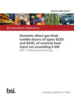
The cabinets or racks to be tested shall be loaded as shown in Figure 1 and Table 1. This is
the condition to be taken as reference.
Cabinets or racks equipped with front/rear doors, and/or side panels may gain structural
contribution from their installation. The test report shall state whether the tested cabinets or
racks were tested with or without doors and panels. Cabinets or racks to be deployed in the
field by the user without doors and/or side panels will require cabinets or racks to be tested
without doors and/or side panels.
600
600
Dummy load M3
Dummy load M5
D = 600 max.
To be attached to the front
and rear verticals
5xA
D
100
A
2 000
Dummy load M4
To be attached to the
bottom
300
400
Z
Y
IEC 1777/11
X
Dimensions in millimetres
Figure 1 – Cabinets or racks configuration for test set up
BS EN 61587-2:2011
–8–
61587-2 © IEC:2011
Table 1 – Load distribution within the cabinet
Cabinets
according
A
(mm)
M3
(kg)
M4
(kg)
M5
(kg)
Total load
(kg)
IEC 60297-3-100
265,9
25 × 4 positions
90
60
250
IEC 60917-2-1
250
25 × 4 positions
90
60
250
4.3
Set up of the cabinets or racks to the vibration table
Mounting condition
IEC 60068-2-47.
is
referred
to
IEC 60068-2-6,
in
which
there
is
reference
to
The loaded cabinets or racks for the test may be mounted to the vibration table without using
interfaces such as concrete anchors, however the securing of the cabinet/rack to vibration
table shall use similar size and number of hold-down devices in accordance with the intended
bolt-down positions of field installed units. If a specific cabinet mounting condition is required,
the test should be performed with agreement between user and manufacture. If there are
several bolt-down patterns for fixing the cabinets or racks to the vibration table, the test shall
be performed under the worst bolt-down condition, that is, the largest stress works to the
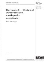
bolts. For the block diagram of the test set-up configuration, see Figure 2.
Displacement
transducer
Cabinet or rack
Motor and actuator
Waveform generator
and controller
Vibration table
Acceleration
monitor
IEC 1778/11
Figure 2 – Block diagram of test set up configuration
4.4
Measurement items
These items shall be measured and reported.
a) Measure the critical frequency and the damping ratio of the loaded cabinets or racks for
test with the sweeping sinusoidal or the random wave before and after the seismic test.
b) Measure the acceleration of the vibration table during the test.
c) Measure the accelerations of horizontal and vertical directions at the top, bottom, and
center of the cabinets or racks.
d) Measure the horizontal displacement of the top of the cabinet or rack at the attachment
point to the vibration table.
BS EN 61587-2:2011
61587-2 © IEC:2011
5
5.1
–9–
Test waveform and acceleration condition
Introductory remarks
The parameters such as time history, zero period acceleration, damping ratio and severities
(frequency range, required response spectrum, acceleration axis) are referred to
IEC 60068-3-3 and 60068-2-57.
5.2
General
The test shall be performed as follows.
a) The test wave for the seismic test shall be a synthesized waveform.
b) The test shall be implemented with single-axis or tri-axial condition defined below, and
which method actually applied shall be recorded.
c) The duration of the strong part of the time history is defined as from the time when the
plot first reaches 25 % of the maximum value to the time when it falls for the last time to
the 25 % level.
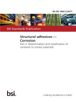
d) The test response spectrum (TRS) shall equal or exceed the required response spectrum
(RRS) as shown in Figure 3 (for single axis) and Figure 5 (for tri-axes). The damping ratio
of 3 % or 2 % is applied to evaluate the TRS and RRS, and is not applied to the frequency
range less than 0,5 Hz and more than 50 Hz. The value of g, i.e., standard acceleration
2
due to the earth, is rounded up to the nearest whole number, that is 10 m/s .
e) The test waveform shall be made to satisfy the RRS.
f)
It is acceptable that the TRS is lower than RRS partially at the frequency range of lower
than half or larger than two-times of the 1st natural frequency, but shall not exceed 20 %
of RRS.
g) If TRS does not satisfy the RRS with the limitation of the displacement of the vibration
table, TRS shall equal or exceed the frequency range equal or larger than 1Hz.
5.3
Single-axis acceleration
a) Accelerate each axis of the vibration table independently.
b) The acceleration of the vibration table is measured during the test as shown 4.3 b).
c) The duration of the strong part of the time history shall be equal or more than 18 s.
2
d) The zero period acceleration of input test wave shall be 16 m/s .
e) The time-history of the test wave is shown in Figure 4.
BS EN 61587-2:2011
– 10 –
61587-2 © IEC:2011
Acceleration (m/s
Acceleration
m/2)s2
100
100
10
10
11
0,1
1
0.1
10
1
100
10
100
Frequency (Hz)
Frequency Hz
IEC 1779/11
2
Acceleration (m/s
) s22
Acceleration
m/
Figure 3 – The RRS for test wave (damping ratio 2 %)
17,5
17.5
15,0
15.0
12,5
12.5
10,0
10.0
7,5
7.5
5,0
5.0
2,5
2.5
0,0
0.0
–2,5
- 2.5
- –5,0
5.0
- –7,5
7.5
–10,0
- 10.0
–12,5
- 12.5
–5,0
-–15,0
15.0
-–17,5
17.5
0,00
0.00
4,00
4.00
8,00
8.00
12,00
12.00
16,00
16.00
20,00
20.00
24,00
24.00
28,00
28.00
32,00
32.00
Time sec.
(s)
Time
IEC 1780/11
Figure 4 – Time-history of the test wave
5.4
Triaxial acceleration
a) Accelerate the vibration table to three axes, i.e., width, depth, and up and down directions
of the cabinets or racks, simultaneously.
b) Acceleration of individual axis is different from each other. The acceleration of the
vibration table is measured during the test as indicated in 4.3 b).
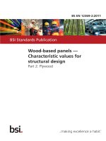
c) The duration of the strong part of the time-history shall be equal or more than 30 s.
d) The required maximum acceleration (zero period acceleration) for input test wave shall be
2
2
12 m/s for horizontal and 6 m/s for up-and-down. The RRS is shown in Figure 5.
e) Examples of time-histories for each axis are shown in Figure 6.
BS EN 61587-2:2011
2
Acceleration (m/s )
– 11 –
4040
Acceleration m/ s
2
61587-2 © IEC:2011
30
30
2020
1010
00 0,1
0.1
1
10
1
10
100
100
Frequency (Hz)
Frequency
Hz
IEC 1781/11
2
Acceleration (m/s )
Acceleration m/ s
2
a) Horizontal
1414
1212
1010
88
66
44
22
00
0,1
0.1
1
10
1
10
100
100
Frequency (Hz)Hz
Frequency
IEC 1782/11
b) Up-and-down
Figure 5 – The RRS for test wave (damping ratio 3 %)
BS EN 61587-2:2011
– 12 –
61587-2 © IEC:2011
2
Acceleration (m/s )
Acceleration m/ s
2
1212
88
44
00
- 4–4
- 8–8
–12
- 12
0
0
10
10
20
20
Time (s) sec
Time s
30
30
40
40
IEC 1783/11
a) longitude
2
Acceleration (m/s )
Acceleration m/ s
2
1212
88
44
00
- 4–4
- 8–8
–12
- 12
0
0
10
10
20
20
Time (s)
Time ssec
30
30
40
40
IEC 1784/11
Acceleration
2
Acceleration (m/s )
m/ s
2
b) latitude
88
66
44
22
00
- 2–2
- 4–4
- 6–6
- 8–8 0
0
10
10
20
20
Time (s)
Time sec
s
30
30
40
40
IEC 1785/11
c) vertical
Figure 6 – Time-history of test wave for each axis
BS EN 61587-2:2011
61587-2 © IEC:2011
6
– 13 –
Assessment following the test
a) There is no permanent deformation to the cabinets or racks exceeding 6 mm or buckling
of any component.
b) There is no crack or break to the structural parts by visual inspection.
c) The displacement of the upper part of the cabinets or racks while the test shall not exceed
75 mm.
d) Subracks or plug-in units installed in the cabinets or racks remain in their installed
position.
e) Doors shall operate as intended after the test.
f)
The covers are not disengaged from the cabinets or racks structures.
g) If the test is done with doors and/or side panels, doors and/or side panels shall not open
and/or fall off during the test.
BS EN 61587-2:2011
– 14 –
61587-2 © IEC:2011
Annex A
(informative)
Vibration generators and information
A.1
Vibration generator types
There are mainly two types of vibration generators, such as a hydraulic servo actuated
generator and an electro-dynamic vibration generator. How to apply either of these is
determined by the test conditions, such as frequency and displacement condition.
The hydraulic servo actuated vibration generator is suitable for vibration with big
displacement (several hundreds of mm) of a low frequency region (several Hz to dozens of
Hz). Therefore, it is possible to reproduce seismic vibration. This vibration generator size, in
almost all cases, is medium to large. On the other hand, the electro-dynamic vibration
generator is suitable for vibration with small displacement (several dozens of mm) of a higher
frequency region (several Hz to several kHz).
A.2
Contact information for waveform data
The contact information regarding waveform data for Figure 4 is as follows:
Telcordia Technologies, Inc.
Information Delivery Organization
The contact information regarding waveform data for Figure 6 is as follows:
NIPPON TELEGRAPH AND TELEPHONE CORPORATION or NTT Facilities, Inc.,
Vibration test waveform data
_____________
This page deliberately left blank
NO COPYING WITHOUT BSI PERMISSION EXCEPT AS PERMITTED BY COPYRIGHT LAW
British Standards Institution (BSI)
BSI is the national body responsible for preparing British Standards and other
standards-related publications, information and services.
BSI is incorporated by Royal Charter. British Standards and other standardization
products are published by BSI Standards Limited.
About us
Revisions
We bring together business, industry, government, consumers, innovators
and others to shape their combined experience and expertise into standards
-based solutions.
Our British Standards and other publications are updated by amendment or revision.
The knowledge embodied in our standards has been carefully assembled in
a dependable format and refined through our open consultation process.
Organizations of all sizes and across all sectors choose standards to help
them achieve their goals.
Information on standards
We can provide you with the knowledge that your organization needs
to succeed. Find out more about British Standards by visiting our website at
bsigroup.com/standards or contacting our Customer Services team or
Knowledge Centre.
Buying standards
You can buy and download PDF versions of BSI publications, including British
and adopted European and international standards, through our website at
bsigroup.com/shop, where hard copies can also be purchased.
If you need international and foreign standards from other Standards Development
Organizations, hard copies can be ordered from our Customer Services team.
Subscriptions
Our range of subscription services are designed to make using standards
easier for you. For further information on our subscription products go to
bsigroup.com/subscriptions.
With British Standards Online (BSOL) you’ll have instant access to over 55,000
British and adopted European and international standards from your desktop.
It’s available 24/7 and is refreshed daily so you’ll always be up to date.
You can keep in touch with standards developments and receive substantial
discounts on the purchase price of standards, both in single copy and subscription
format, by becoming a BSI Subscribing Member.
PLUS is an updating service exclusive to BSI Subscribing Members. You will
automatically receive the latest hard copy of your standards when they’re
revised or replaced.
To find out more about becoming a BSI Subscribing Member and the benefits
of membership, please visit bsigroup.com/shop.
With a Multi-User Network Licence (MUNL) you are able to host standards
publications on your intranet. Licences can cover as few or as many users as you
wish. With updates supplied as soon as they’re available, you can be sure your
documentation is current. For further information, email
BSI Group Headquarters
389 Chiswick High Road London W4 4AL UK
We continually improve the quality of our products and services to benefit your
business. If you find an inaccuracy or ambiguity within a British Standard or other
BSI publication please inform the Knowledge Centre.
Copyright
All the data, software and documentation set out in all British Standards and
other BSI publications are the property of and copyrighted by BSI, or some person
or entity that owns copyright in the information used (such as the international
standardization bodies) and has formally licensed such information to BSI for
commercial publication and use. Except as permitted under the Copyright, Designs
and Patents Act 1988 no extract may be reproduced, stored in a retrieval system
or transmitted in any form or by any means – electronic, photocopying, recording
or otherwise – without prior written permission from BSI. Details and advice can
be obtained from the Copyright & Licensing Department.
Useful Contacts:
Customer Services
Tel: +44 845 086 9001
Email (orders):
Email (enquiries):
Subscriptions
Tel: +44 845 086 9001
Email:
Knowledge Centre
Tel: +44 20 8996 7004
Email:
Copyright & Licensing
Tel: +44 20 8996 7070
Email: