Bsi bs en 61857 21 2009
Bạn đang xem bản rút gọn của tài liệu. Xem và tải ngay bản đầy đủ của tài liệu tại đây (1.76 MB, 22 trang )
BS EN 61857-21:2009
BSI British Standards
Electrical insulation systems —
Procedures for thermal
evaluation —
Part 21: Specific requirements for general-purpose
models — Wire-wound applications
NO COPYING WITHOUT BSI PERMISSION EXCEPT AS PERMITTED BY COPYRIGHT LAW
raising standards worldwide™
BRITISH STANDARD
BS EN 61857-21:2009
National foreword
This British Standard is the UK implementation of EN 61857-21:2009. It is
identical to IEC 61857-21:2009. It supersedes BS EN 61857-21:2004 which is
withdrawn.
The UK participation in its preparation was entrusted to Technical Committee
GEL/112, Evaluation and qualification of electrical insulating materials and
systems.
A list of organizations represented on this committee can be obtained on
request to its secretary.
This publication does not purport to include all the necessary provisions of a
contract. Users are responsible for its correct application.
© BSI 2009
ISBN 978 0 580 62004 1
ICS 29.080.30
Compliance with a British Standard cannot confer immunity from
legal obligations.
This British Standard was published under the authority of the Standards
Policy and Strategy Committee on 31 October 2009
Amendments issued since publication
Amd. No.
Date
标准分享网 www.bzfxw.com 免费下载
Text affected
BS EN 61857-21:2009
EUROPEAN STANDARD
EN 61857-21
NORME EUROPÉENNE
July 2009
EUROPÄISCHE NORM
ICS 29.080.30
Supersedes EN 61857-21:2004
English version
Electrical insulation systems Procedures for thermal evaluation Part 21: Specific requirements for general-purpose models Wire-wound applications
(IEC 61857-21:2009)
Systèmes d'isolation électrique Procédures d'évaluation thermique Partie 21: Exigences particulières
pour les modèles d'usage général Applications aux enroulements à fil
(CEI 61857-21:2009)
Elektrische Isoliersysteme Verfahren zur thermischen Bewertung Teil 21: Spezielle Bedingungen
für Mehrzweckmodelle Anwendungen bei Drahtwicklungen
(IEC 61857-21:2009)
www.bzfxw.com
This European Standard was approved by CENELEC on 2009-06-01. CENELEC members are bound to comply
with the CEN/CENELEC Internal Regulations which stipulate the conditions for giving this European Standard
the status of a national standard without any alteration.
Up-to-date lists and bibliographical references concerning such national standards may be obtained on
application to the Central Secretariat or to any CENELEC member.
This European Standard exists in three official versions (English, French, German). A version in any other
language made by translation under the responsibility of a CENELEC member into its own language and notified
to the Central Secretariat has the same status as the official versions.
CENELEC members are the national electrotechnical committees of Austria, Belgium, Bulgaria, Cyprus, the
Czech Republic, Denmark, Estonia, Finland, France, Germany, Greece, Hungary, Iceland, Ireland, Italy, Latvia,
Lithuania, Luxembourg, Malta, the Netherlands, Norway, Poland, Portugal, Romania, Slovakia, Slovenia, Spain,
Sweden, Switzerland and the United Kingdom.
CENELEC
European Committee for Electrotechnical Standardization
Comité Européen de Normalisation Electrotechnique
Europäisches Komitee für Elektrotechnische Normung
Central Secretariat: Avenue Marnix 17, B - 1000 Brussels
© 2009 CENELEC -
All rights of exploitation in any form and by any means reserved worldwide for CENELEC members.
Ref. No. EN 61857-21:2009 E
BS EN 61857-21:2009
EN 61857-21:2009
-2-
Foreword
The text of document 112/120/FDIS, future edition 3 of IEC 61857-21, prepared by IEC TC 112,
Evaluation and qualification of electrical insulating materials and systems, was submitted to the
IEC-CENELEC parallel vote and was approved by CENELEC as EN 61857-21 on 2009-06-01.
This European Standard supersedes EN 61857-21:2004.
The editorial revisions make EN 61857-21:2009 compatible with Parts 1 and 22.
The following dates were fixed:
– latest date by which the EN has to be implemented
at national level by publication of an identical
national standard or by endorsement
(dop)
2010-03-01
– latest date by which the national standards conflicting
with the EN have to be withdrawn
(dow)
2012-06-01
Annex ZA has been added by CENELEC.
__________
Endorsement notice
The text of the International Standard IEC 61857-21:2009 was approved by CENELEC as a European
Standard without any modification.
www.bzfxw.com
__________
标准分享网 www.bzfxw.com 免费下载
BS EN 61857-21:2009
-3-
EN 61857-21:2009
Annex ZA
(normative)
Normative references to international publications
with their corresponding European publications
The following referenced documents are indispensable for the application of this document. For dated
references, only the edition cited applies. For undated references, the latest edition of the referenced
document (including any amendments) applies.
NOTE When an international publication has been modified by common modifications, indicated by (mod), the relevant EN/HD
applies.
Publication
Year
IEC 60455
IEC 60464
EN/HD
Year
Series Resin based reactive compounds used for
electrical insulation
EN 60455
Series
Series Varnishes used for electrical insulation
EN 60464
Series
EN 60505
2004
1)
IEC 60505
-
IEC 61857-1
2008
Title
Evaluation and qualification of electrical
insulation systems
Electrical insulation systems - Procedures for EN 61857-1
thermal evaluation Part 1: General requirements - Low-voltage
www.bzfxw.com
1)
Undated reference.
2)
Valid edition at date of issue.
2009
2)
–2–
BS EN 61857-21:2009
61857-21 © IEC:2009
CONTENTS
FOREWORD...........................................................................................................................3
INTRODUCTION .....................................................................................................................5
1
Scope ...............................................................................................................................6
2
Normative references........................................................................................................6
3
Terms and definitions .......................................................................................................6
4
Construction .....................................................................................................................7
5
4.1 General information .................................................................................................7
4.2 Model components ..................................................................................................8
4.3 Assembly of the model........................................................................................... 11
Number of test objects .................................................................................................... 12
6
Test procedure ............................................................................................................... 12
6.1
6.2
7
General ................................................................................................................. 12
Initial screening test............................................................................................... 12
6.2.1 General ..................................................................................................... 12
6.2.2 Initial dielectric test .................................................................................... 12
6.3 Thermal endurance test ......................................................................................... 13
6.3.1 Endurance test cycle.................................................................................. 13
6.3.2 Thermal ageing.......................................................................................... 13
6.3.3 Mechanical stress ...................................................................................... 13
6.3.4 Thermal shock ........................................................................................... 13
6.3.5 Moisture exposure ..................................................................................... 14
6.3.6 Dielectric diagnostic test ............................................................................ 14
End-of-life criterion ......................................................................................................... 14
8
Analysing, reporting and classification............................................................................. 15
www.bzfxw.com
Bibliography .......................................................................................................................... 16
Figure 1 – Photos of GPM and GPM-TC test objects................................................................7
Figure 2 – Schematic drawing of a GPM frame .......................................................................9
Figure 3 – Manufacturing drawing of a GPM-TC frame........................................................... 10
Table 1 – Initial dielectric test ................................................................................................ 13
Table 2 – Dielectric diagnostic test ........................................................................................ 14
标准分享网 www.bzfxw.com 免费下载
BS EN 61857-21:2009
61857-21 © IEC:2009
–3–
INTERNATIONAL ELECTROTECHNICAL COMMISSION
___________
ELECTRICAL INSULATION SYSTEMS –
PROCEDURES FOR THERMAL EVALUATION –
Part 21: Specific requirements for general-purpose models –
Wire-wound applications
FOREWORD
1) The International Electrotechnical Commission (IEC) is a worldwide organization for standardization comprising
all national electrotechnical committees (IEC National Committees). The object of IEC is to promote
international co-operation on all questions concerning standardization in the electrical and electronic fields. To
this end and in addition to other activities, IEC publishes International Standards, Technical Specifications,
Technical Reports, Publicly Available Specifications (PAS) and Guides (hereafter referred to as “IEC
Publication(s)”). Their preparation is entrusted to technical committees; any IEC National Committee interested
in the subject dealt with may participate in this preparatory work. International, governmental and nongovernmental organizations liaising with the IEC also participate in this preparation. IEC collaborates closely
with the International Organization for Standardization (ISO) in accordance with conditions determined by
agreement between the two organizations.
2) The formal decisions or agreements of IEC on technical matters express, as nearly as possible, an international
consensus of opinion on the relevant subjects since each technical committee has representation from all
interested IEC National Committees.
3) IEC Publications have the form of recommendations for international use and are accepted by IEC National
Committees in that sense. While all reasonable efforts are made to ensure that the technical content of IEC
Publications is accurate, IEC cannot be held responsible for the way in which they are used or for any
misinterpretation by any end user.
www.bzfxw.com
4) In order to promote international uniformity, IEC National Committees undertake to apply IEC Publications
transparently to the maximum extent possible in their national and regional publications. Any divergence
between any IEC Publication and the corresponding national or regional publication shall be clearly indicated in
the latter.
5) IEC provides no marking procedure to indicate its approval and cannot be rendered responsible for any
equipment declared to be in conformity with an IEC Publication.
6) All users should ensure that they have the latest edition of this publication.
7) No liability shall attach to IEC or its directors, employees, servants or agents including individual experts and
members of its technical committees and IEC National Committees for any personal injury, property damage or
other damage of any nature whatsoever, whether direct or indirect, or for costs (including legal fees) and
expenses arising out of the publication, use of, or reliance upon, this IEC Publication or any other IEC
Publications.
8) Attention is drawn to the Normative references cited in this publication. Use of the referenced publications is
indispensable for the correct application of this publication.
9) Attention is drawn to the possibility that some of the elements of this IEC Publication may be the subject of
patent rights. IEC shall not be held responsible for identifying any or all such patent rights.
International Standard IEC 61857-21 has been prepared by IEC technical committee 112:
Evaluation and qualification of electrical insulating materials and systems.
This third edition cancels and replaces the second edition published in 2004, and constitutes
editorial revisions to make this standard compatible with Parts 1 and 22.
The text of this standard is based on the following documents:
FDIS
Report on voting
112/120/FDIS
112/126/RVD
Full information on the voting for the approval of this standard can be found in the report on
voting indicated in the above table.
–4–
BS EN 61857-21:2009
61857-21 © IEC:2009
This publication has been drafted in accordance with the ISO/IEC Directives, Part 2.
A list of all the parts in the IEC 61857 series, under the general title Electrical insulation
systems – Procedures for thermal evaluation, can be found on the IEC website.
The committee has decided that the contents of this publication will remain unchanged until the
maintenance result date indicated on the IEC web site under "" in the data
related to the specific publication. At this date, the publication will be
•
•
•
•
reconfirmed,
withdrawn,
replaced by a revised edition, or
amended.
www.bzfxw.com
标准分享网 www.bzfxw.com 免费下载
BS EN 61857-21:2009
61857-21 © IEC:2009
–5–
INTRODUCTION
A series of parts that will make up IEC 61857 is currently being developed, each of which will
address a specific test object and/or application with an associated test procedure.
www.bzfxw.com
–6–
BS EN 61857-21:2009
61857-21 © IEC:2009
ELECTRICAL INSULATION SYSTEMS –
PROCEDURES FOR THERMAL EVALUATION –
Part 21: Specific requirements for general-purpose models –
Wire-wound applications
1
Scope
This part of IEC 61857 describes a general-purpose model (GPM) and a tall channel alternative
model (GPM-TC) which can be used for the evaluation of wire-wound electrical insulation
systems (EIS) where specific electrotechnical products are not available or required.
2
Normative references
The following referenced documents are indispensable for the application of this document. For
dated references, only the edition cited applies. For undated references, the latest edition of
the referenced document (including any amendments) applies.
IEC 60455 (all parts), Resin based reactive compounds used for electrical insulation
IEC 60464: (all parts), Varnishes used for electrical insulation
www.bzfxw.com
IEC 60505, Evaluation and qualification of electrical insulation systems
IEC 61857-1, 2008, Electrical insulation systems – Procedures for thermal evaluation –
Part 1: General requirements – Low-voltage
3
Terms and definitions
For the purposes of this document, the terms and definitions given in IEC 60505 and
IEC 61857-1, as well as the following definitions, apply.
3.1
earth
ground
make an electric connection between a given point in a system, an installation or in equipment
and a local earth
[IEV 195-01-08]
3.2
earth (ground) insulation
electrical insulating material (EIM) between a coil and earthed metal
3.3
coil
continuous winding of insulated wire
3.4
coil-to-coil insulation
electrical insulating material (EIM) between individual coils
标准分享网 www.bzfxw.com 免费下载
BS EN 61857-21:2009
61857-21 © IEC:2009
4
4.1
–7–
Construction
General information
General-purpose models are useful in evaluating the compatibility of the electrical insulation
materials (EIM) being used in a candidate electrical insulation system (EIS). A GPM is not
capable of simulating the influence of actual manufacturing processes such as winding
techniques. Consequently, the influence of the manufacturing processes will be minimal. A
GPM may be assembled by hand, using simple facilities.
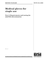
The essential components of general-purpose models are either two coils (GPM) or three coils
(GPM-TC) mounted in the same pair of channels, thus representing the windings in the window
of a transformer, or the windings in the slots of a motor or generator, and EIM placed between
the pairing(s) of coils and the coil-to-frame location representing coil-to-coil insulation and
earth insulation, respectively (see Figure 1).
www.bzfxw.com
IEC
665/09
NOTE The additional height of the channel area in the GPM-TC allows for evaluation of three coils of winding wire
and the extra pair of stand-offs allows for electrical testing of the additional coil.
Figure 1 – GPM test object
The channels, representative of the laminations in an electrotechnical product, shall be formed of
stainless steel plates in an appropriate manner and fixed to the base. One or more EIM and/or
different thicknesses of EIM may be used as earth insulation in the construction. Two insulators
for each coil shall be fixed to the base.
The coils shall be wound with two winding wires in parallel (bifilar winding). The sets of
windings should fill the channels. Each coil may be wound with a different type of winding wire
and each type of winding wire shall be in contact with the earth insulation and coil-to-coil
insulation. The coils shall be connected to the insulators so as to facilitate the dielectric testing
from coil-to-frame, coil-to-coil and conductor-to-conductor.
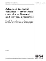
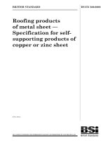
Refer to Figure 2 for the principles of construction of the GPM and to Figure 3 for the principles
of construction of the GPM-TC.
–8–
4.2
BS EN 61857-21:2009
61857-21 © IEC:2009
Model components
The components of the model are as follows:
a) Frame:
The frame consists of a rigid supporting metal base with suitable stand-off insulators of
porcelain or other appropriate material bolted to one end, and with two channels, formed by
an inner and outer sheet, bolted to the other end. See Figure 2 or 3 for specific dimensions.
The supporting base has holes for mounting the model during application of mechanical
stress (vibration). The assembled channel portion contains two or three coils insulated from
the frame by earth insulation, insulated from each other by coil-to-coil insulation and held in
place by channel wedges.
b) Coils:
Each coil shall be wound with parallel winding wires for the conductor-to-conductor
dielectric test. Coils may be machine-wound, or hand-wound on pins or forms. The ends of
the parallel windings shall be isolated to allow conductor-to-conductor testing.
When the GPM-TC is being used to evaluate more than one type of winding wire, the EIM
being evaluated as coil-to-coil insulation must be placed such that each EIM is in contact
with each type of winding wire.
c) Winding wire:
Heavy film-coated. A wire size with a nominal diameter of 1,0 mm to 1,12 mm is preferred.
d) EIM:
EIM is used as earth insulation in the channel and as coil-to-coil insulation. EIM qualified as
either earth insulation or coil-to-coil insulation in an EIS may be used in either case. EIM
shall represent the thickness to be evaluated. EIM placed between the coils shall be of
sufficient width to provide a complete insulation barrier between the coils. The EIM in the
semicircular section shall be shaped, by cutting or other technique, to follow the curve of
the coils and extend wider than the width of the wire wound coils. When the GPM-TC is
being used to evaluate the performance of two sets of EIM, it is essential for each type of
EIM to be in contact with each type of winding wire. If the EIM placed between the top and
middle coils is not the same as that placed between the middle and bottom coils, then the
winding wire placed into the top coil shall be the same as is placed into the bottom coil. The
middle coil may be wound with an alternate winding wire.
www.bzfxw.com
e)
Channel wedge:
The wedges shall be of sufficient stiffness to contain the coils in the channel. One end of
the wedge shall be rounded to ensure easy passage through the channel.
f)
Tie cord and/or electrical grade tape.
g) Electrical insulating varnish or resin, if a component of the EIS, shall conform to either
IEC 60455 or IEC 60464.
标准分享网 www.bzfxw.com 免费下载
BS EN 61857-21:2009
61857-21 © IEC:2009
–9–
Dimensions in millimetres ± 10 %
Drill four holes of 4 mm in
diameter for mounting
insulators
Drill two holes of 4,5 mm in
diameter for mounting frame
157
19
A
50
30
11
8
A
11
51
54
206
Stainless steel plate
www.bzfxw.com
Stainless steel plate
Hexagonal HD stainless steel
bolts and nuts – Two holes of
8 mm in diameter
5°
Channel assembly of
1,6 mm stainless steel
5°
45°
3
19
45 approximately
13
10
10
38
Remove all burrs and
grind all edges smooth
50
64
Section A-A
Figure 2 – Schematic drawing of a GPM frame
IEC 666/09
BS EN 61857-21:2009
61857-21 © IEC:2009
– 10 –
Dimensions in millimetres ± 10 %
Drill two holes of 4,5 mm in
diameter for mounting frame
Drill six holes of 4 mm in
diameter for mounting insulators
157
19
A
11
9,5
50
25,4
9,5
19
8
A
51
54
206
Stainless steel plate
www.bzfxw.com
Stainless steel plate
Hexagonal head, stainless steel
bolts and nuts – Two holes
8 mm in diameter
5°
5°
Channel assembly of
1,6 mm stainless steel
45°
3
30
55 approximately
13
10
10
38
Remove all burrs and grind
all edges smooth
50
64
Section A-A
Figure 3 – Manufacturing drawing of a GPM-TC frame
标准分享网 www.bzfxw.com 免费下载
IEC 667/09
BS EN 61857-21:2009
61857-21 © IEC:2009
4.3
– 11 –
Assembly of the model
Assemble the model as follows:
a) Each coil shall be wound on a coil former with two parallel sides and with semicircles at
both ends. The parallel sides shall have a length of 65 mm and the semicircles shall have a
diameter of 45 mm. Each coil shall be composed of a sufficient number of turns of winding
wire to fill either half (GPM) or one-third (GPM-TC) of the channel, leaving room for the EIM
and the wedge. The unconnected ends shall be prepared by cutting off one end of each of
the bifilar wires, leaving a length of 5 mm from the coil near the middle of one of the
semicircles. The two unconnected ends shall be separated from each other and from the
coil by a minimum of 5 mm to ensure isolation and allow conductor-to-conductor dielectric
testing. A sufficient length of the other conductor ends shall be brought out from the
straight portion of the coil for attachment to the stand-off insulators. Individual coils shall be
secured with tie cord or electrical grade tape.
b) Before assembly, each metal component of the model shall be completely clean and dry.
These metal components shall be carefully assembled ensuring that the channels are equal
in width and the sides parallel. A simple procedure for this is to cut two wooden blocks
equal in width to the channel openings and to centre the channels by placing the blocks in
the channels prior to tightening the hold-down bolts.
c) The channel insulation shall be cut from a piece of the EIM of a thickness to be evaluated
as a 65 mm square for a GPM, or a 65 mm × 90 mm rectangle for a GPM-TC, and bent to
fit the channel. This allows the EIM to project out of the top of the channel so it can be
folded under the wedge and to project 5 mm from each end of the channel. If more than
one EIM is to be used on the channel, appropriately sized pieces shall be used to provide a
5 mm overlap of each ground insulation within the channel and allow the earth insulation to
project 5 mm from each end of the channel. Not more than three EIMs shall be placed into
a channel section.
www.bzfxw.com
d) When inserting the coils, the channel insulation shall be folded back over the top edge of
the channel to ensure that the winding wire is not nicked or abraded when being placed in
the channel. The bottom coil shall be inserted into the channel with the unconnected
conductor ends facing down and the leads at the top of the coil. After the bottom coil is in
place, a layer of coil-to-coil insulation shall then be inserted to ensure that the coil-to-coil
insulation within the channel completely covers the bottom coil, so to provide a complete
insulating barrier between coils. For a GPM-TC model, the middle coil shall then be
inserted with the unconnected ends on the opposite side from the unconnected ends of the
bottom coil, and a second layer of coil-to-coil insulation shall be inserted to completely
cover the middle coil. The top coil shall be inserted with the unconnected ends on the
opposite side from the unconnected ends of the adjacent coil. If more than one EIM is to be
evaluated in a coil-to-coil location, appropriately sized pieces shall be used to provide a
5 mm overlap of each EIM and to project 5 mm from the end of each channel. EIM placed
between the coils in the semicircular end sections shall overlap the EIM projecting from the
channel section. With the coils and coil-to-coil insulation in place, the ends of the channel
insulation shall be folded over the top of the top coil and the wedge inserted on top of the
channel insulation. The wedges shall be at least 10 mm wide and 75 mm long.
e) The leads shall be measured to terminate at the insulated terminals. An appropriate portion
of the leads shall be stripped of insulation and may be tinned at the end with solder before
connecting to the terminals. Each lead shall be connected to an individual terminal. When
appropriate, prior to any varnish or resin treatment, the coils may be checked for insulation
continuity by a conductor-to-conductor test according to 6.1.
f)
When appropriate, the varnish or resin treatment shall be performed using the same
impregnating material as anticipated in production, and cured according to the
manufacturer's recommendations. Each test object should be dipped, drained, and cured in
– 12 –
BS EN 61857-21:2009
61857-21 © IEC:2009
a vertical position. If more than one impregnation treatment is required to achieve sufficient
bonding, it shall be so stated in the test report.
g) For each exposure temperature, a set of test objects is bolted to a rack made of rigid
aluminium approximately 15 mm thick. The rack shall be constructed with large openings
between the test objects so that air circulation is not impeded. The rack should be sized to
fit the ovens and condensation chamber and be capable of being secured to the vibration
table.
5
Number of test objects
The minimum number of test objects in a group for each ageing temperature shall be ten.
6
Test procedure
6.1
General
All test objects shall be subjected to initial screening tests followed by repeated thermal
endurance test cycles consisting of subcycles in the following order:
a) a thermal ageing subcycle;
b) a subcycle of pre-diagnostic mechanical stress, thermal shock and moisture exposure, in
that order;
c) a dielectric diagnostic test.
6.2
6.2.1
www.bzfxw.com
Initial screening test
General
Prior to exposure to an elevated temperature on the first thermal ageing subcycle, all test
objects shall be subjected to initial screening tests in order to eliminate defective test objects.
The initial screening tests shall consist of the following steps and shall be conducted in the
order given:
a) visual inspection;
b) initial dielectric test (see 6.2.2);
c) mechanical stress (see 6.3.3);
d) thermal shock, as required (see 6.3.4 );
e) moisture exposure (see 6.3.5);
f) dielectric diagnostic test (see 6.3.6).
6.2.2
Initial dielectric test
An initial screening test utilizing dielectric techniques shall be performed on each test object
prior to application of other pre-diagnostic stresses and thermal ageing, see Table 1.
标准分享网 www.bzfxw.com 免费下载
BS EN 61857-21:2009
61857-21 © IEC:2009
– 13 –
Table 1 – Initial dielectric test
Stressed EIM
Conductor-to-conductor
Coil-to-coil
a
Coil-to-frame
a
Voltage
V
Acceptance criteria
mA
400 ± 40
≤40
2 000 ± 100
≤40
2 000 ± 100
≤40
Test the top-to-middle coil separately from the middle-to-bottom coil on GPM-TC test objects.
The following procedure shall then be followed:
•
an initial dielectric test voltage shall be applied for a minimum of 60 s;
•
the frequency of the test voltage shall be between 48 Hz and 62 Hz.
NOTE Instantaneous application of full voltage is not recommended. It is recommended that surge protectors
be included in the test circuit to eliminate unintended high-voltage spikes.
For test objects evaluated by applied voltage, pre-calibrated electromechanical over-current
circuit-breakers with a trip time of 2 s to 3 s have been used successfully to detect failure.
The cause of failure shall be determined. When the failure is within the EIS, it shall eliminate
that test object from further testing. When the failure is not within the EIS and it can be
repaired without disturbing the EIS, that test object may be retested and returned to the test
programme if it passes.
6.3
6.3.1
www.bzfxw.com
Thermal endurance test
Endurance test cycle
Following the initial screening tests, all test objects shall be subjected to repeated thermal
endurance test cycles consisting of subcycles in the following order:
a) thermal ageing subcycle;
b) mechanical stress subcycle;
c) thermal shock subcycle;
d) moisture exposure subcycle;
e) dielectric diagnostic test.
6.3.2
Thermal ageing
Thermal ageing, comprising selection of ageing temperature, initial ageing periods and ageing
procedures, shall be conducted in accordance with 6.3 of IEC 61857-1:2008.
Ovens shall be used as the means of heating in accordance with 6.3.4 of IEC 61857-1:2008.
6.3.3
Mechanical stress
Mechanical stress shall be applied by mounting test objects on a vibration table and exposing
them for (60 ± 5) min of sinusoidal vibration at a frequency between 48 Hz to 62 Hz, with an
acceleration of (15 ± 3) ms –2 . No voltage shall be applied during this period.
6.3.4
Thermal shock
Unless agreed to by all interested parties, both the reference and candidate EIS shall be
exposed to a low-temperature thermal shock. Thermal shock shall be applied by placing
– 14 –
BS EN 61857-21:2009
61857-21 © IEC:2009
room temperature test objects into a low-temperature chamber at (–20 ± 5) °C for at least 2 h.
No voltage shall be applied during this period.
6.3.5
Moisture exposure
Moisture exposure, with visible condensation, shall be applied in accordance with 6.6 of
IEC 61857-1:2008.
6.3.6
Dielectric diagnostic test
Following each ageing cycle and set of subcycles, described in 6.3.3 through 6.3.5, evaluate
the test objects in accordance with the dielectric diagnostic test given in Table 2.
The surface of the test objects shall be wiped free of any water droplets immediately before
application of voltage.
Table 2 – Dielectric diagnostic test
Stressed EIM
Conductor-to-conductor
Coil-to-coil
a
Coil-to-frame
a
Voltage
V
End-of-life
A
110 ± 10
0,5 to 0,75
600 ± 30
0,5 to 0,75
600 ± 30
0,5 to 0,75
Test the top-to-middle coil separately from the middle-to-bottom coil on GPM-TC test objects.
www.bzfxw.com
The following steps shall then be taken:
•
dielectric diagnostic test voltages shall be applied for a minimum of 10 min;
•
failure shall be current flow as defined above prior to completion of the time period;
•
the frequency of the test voltage shall be between 48 Hz and 62 Hz.
NOTE Instantaneous application of full voltage is not recommended. It is recommended that surge protectors be
included in the test circuit to eliminate unintended high voltage spikes.
For test objects evaluated by applied voltage, pre-calibrated electromechanical over-current
circuit-breakers with a trip time of 2 s to 3 s have been used successfully to detect failure.
In order to check the condition of the test objects and determine end-of-life, the dielectric
diagnostic test shall be applied after each successive exposure to moisture either while
the test objects are still in the condensation chamber or immediately after removal while still
wet with moisture.
7
End-of-life criterion
The end-of-life criterion for individual test specimens shall be failure of a test object to hold the
applied voltage for the required time period shown in Table 2. The cause of failure shall be
determined. When the failure is within the EIS, it shall eliminate that test object from further
testing. When the failure is not within the EIS and it can be repaired without disturbing the EIS,
that test object may be retested and returned to the test programme.
标准分享网 www.bzfxw.com 免费下载
BS EN 61857-21:2009
61857-21 © IEC:2009
8
– 15 –
Analysing, reporting and classification
Analysing, reporting
IEC 61857-1:2008.
and
classification
shall
be
in
accordance
with
www.bzfxw.com
Clause
7
of
– 16 –
BS EN 61857-21:2009
61857-21 © IEC:2009
Bibliography
IEC 60050-195, International Electrotechnical Vocabulary – Part 195: Earthing and protection
against electric shock
___________
www.bzfxw.com
标准分享网 www.bzfxw.com 免费下载
www.bzfxw.com
This page deliberately left blank
British Standards Institution (BSI)
BSI is the independent national body responsible for preparing British Standards.
It presents the UK view on standards in Europe and at the international level.
It is incorporated by Royal Charter.
Revisions
Information on standards
British Standards are updated by amendment or revision. Users of British
Standards should make sure that they possess the latest amendments or
editions.
It is the constant aim of BSI to improve the quality of our products and
services. We would be grateful if anyone finding an inaccuracy or
ambiguity while using this British Standard would inform the Secretary of
the technical committee responsible, the identity of which can be found
on the inside front cover.
Tel: +44 (0)20 8996 9000 Fax: +44 (0)20 8996 7400
BSI offers members an individual updating service called PLUS which
ensures that subscribers automatically receive the latest editions of
standards.
BSI provides a wide range of information on national, European and
international standards through its Library.
Various BSI electronic information services are also available which give
details on all its products and services. Contact the Information Centre.
Tel: +44 (0)20 8996 7111
Fax: +44 (0)20 8996 7048 Email:
Subscribing members of BSI are kept up to date with standards
developments and receive substantial discounts on the purchase price
of standards. For details of these and other benefits contact Membership
Administration.
Tel: +44 (0)20 8996 7002 Fax: +44 (0)20 8996 7001
Email:
Information regarding online access to British Standards via British
Standards Online can be found at www.bsigroup.com/BSOL
Further information about BSI is available on the BSI website at
www.bsigroup.com
www.bzfxw.com
Buying standards
Orders for all BSI, international and foreign standards publications
should be addressed to BSI Customer Services.
Tel: +44 (0)20 8996 9001 Fax: +44 (0)20 8996 7001
Email:
You may also buy directly using a debit/credit card from the BSI Shop
on the website www.bsigroup.com/shop
In response to orders for international standards, it is BSI policy to
supply the BSI implementation of those that have been published
as British Standards, unless otherwise requested.
Copyright
Copyright subsists in all BSI publications. BSI also holds the copyright, in the UK, of the
publications of the international standardization bodies. Except as permitted under the
Copyright, Designs and Patents Act 1988 no extract may be reproduced, stored in a retrieval
system or transmitted in any form or by any means – electronic, photocopying, recording or
otherwise – without prior written permission from BSI.
This does not preclude the free use, in the course of implementing the standard of necessary
details such as symbols, and size, type or grade designations. If these details are to be used for
any other purpose than implementation then the prior written permission of BSI must be
obtained. Details and advice can be obtained from the Copyright & Licensing Manager.
Tel: +44 (0)20 8996 7070 Email:
BSI Group Headquarters
389 Chiswick High Road London W4 4AL UK
Tel +44 (0)20 8996 9001
Fax +44 (0)20 8996 7001
www.bsigroup.com/standards
raising standards worldwide™
标准分享网 www.bzfxw.com 免费下载