Bsi bs en 62471 2008 (2009)
Bạn đang xem bản rút gọn của tài liệu. Xem và tải ngay bản đầy đủ của tài liệu tại đây (1.76 MB, 52 trang )
BS EN 62471:2008
BSI British Standards
Photobiological safety of lamps
and lamp systems
NO COPYING WITHOUT BSI PERMISSION EXCEPT AS PERMITTED BY COPYRIGHT LAW
raising standards worldwide™
BRITISH STANDARD
BS EN 62471:2008
National foreword
This British Standard is the UK implementation of EN 62471:2008. It was
derived by CENELEC from IEC 62471:2006. Together with BS EN 60825-1:2007,
it supersedes BS EN 60825-1:1994 which is withdrawn.
The CENELEC common modifications have been implemented at the
appropriate places in the text and are indicated by tags (e.g.).
The UK participation in its preparation was entrusted to Technical Committee
EPL/76, Optical radiation safety and laser equipment.
A list of organizations represented on this committee can be obtained on
request to its secretary.
This publication does not purport to include all the necessary provisions of a
contract. Users are responsible for its correct application.
© BSI 2009
ISBN 978 0 580 56886 2
ICS 29.140.01
Compliance with a British Standard cannot confer immunity from
legal obligations.
This British Standard was published under the authority of the Standards
Policy and Strategy Committee on 31 March 2009
Amendments issued since publication
Amd. No.
Date
Text affected
EUROPEAN STANDARD
EN 62471
NORME EUROPÉENNE
September 2008
EUROPÄISCHE NORM
ICS 29.140
Partially supersedes EN 60825-1:1994 + A1:2002 + A2:2001
English version
Photobiological safety of lamps and lamp systems
(IEC 62471:2006, modified)
Sécurité photobiologique des lampes
et des appareils utilisant des lampes
(CEI 62471:2006, modifiée)
Photobiologische Sicherheit
von Lampen und Lampensystemen
(IEC 62471:2006, modifiziert)
This European Standard was approved by CENELEC on 2008-09-01. CENELEC members are bound to comply
with the CEN/CENELEC Internal Regulations which stipulate the conditions for giving this European Standard
the status of a national standard without any alteration.
Up-to-date lists and bibliographical references concerning such national standards may be obtained on
application to the Central Secretariat or to any CENELEC member.
This European Standard exists in three official versions (English, French, German). A version in any other
language made by translation under the responsibility of a CENELEC member into its own language and notified
to the Central Secretariat has the same status as the official versions.
CENELEC members are the national electrotechnical committees of Austria, Belgium, Bulgaria, Cyprus, the
Czech Republic, Denmark, Estonia, Finland, France, Germany, Greece, Hungary, Iceland, Ireland, Italy, Latvia,
Lithuania, Luxembourg, Malta, the Netherlands, Norway, Poland, Portugal, Romania, Slovakia, Slovenia, Spain,
Sweden, Switzerland and the United Kingdom.
CENELEC
European Committee for Electrotechnical Standardization
Comité Européen de Normalisation Electrotechnique
Europäisches Komitee für Elektrotechnische Normung
Central Secretariat: rue de Stassart 35, B - 1050 Brussels
© 2008 CENELEC -
All rights of exploitation in any form and by any means reserved worldwide for CENELEC members.
Ref. No. EN 62471:2008 E
BS EN 62471:2008
EN 62471:2008
-2-
Foreword
The text of the International Standard IEC 62471:2006, prepared by IEC TC 76 "Optical radiation
safety and laser equipment", together with the common modifications prepared by the Technical
Committee CENELEC TC 76, Optical radiation safety and laser equipment, was submitted to the
formal vote and was approved by CENELEC as EN 62471 on 2008-09-01.
This European Standard partially supersedes EN 60825-1:1994 + corrigendum February 1995 +
A1:2002 + A2:2001 + A2:2001/corrigendum April 2004.
The following dates were fixed:
– latest date by which the EN has to be implemented
at national level by publication of an identical
national standard or by endorsement
(dop)
2009-09-01
– latest date by which the national standards conflicting
with the EN have to be withdrawn
(dow)
2011-09-01
Annex ZA has been added by CENELEC.
__________
62471 © IEC:2006
–3–
BS EN 62471:2008
CONTENTS
FOREWORD ............................................................................................................................................5
INTRODUCTION ..................................................................................................................................... 7
1.
SCOPE ...........................................................................................................................................8
2.
NORMATIVE REFERENCES ........................................................................................................8
3.
DEFINITIONS, SYMBOLS AND ABBREVIATIONS.......................................................................8
4.
EXPOSURE LIMITS .....................................................................................................................14
5.
MEASUREMENT OF LAMPS AND LAMP SYSTEMS.................................................................15
5.1 Measurement conditions ....................................................................................................15
5.1.1
Lamp ageing (seasoning) ...................................................................................15
5.1.2
Test environment ................................................................................................16
5.1.3
Extraneous radiation...........................................................................................16
5.1.4
Lamp operation...................................................................................................16
5.1.5
Lamp system operation ......................................................................................16
5.2 Measurement procedure ........................................................................................................16
5.2.1
Irradiance measurements...................................................................................16
5.2.2
Radiance measurements....................................................................................18
5.2.3
Measurement of source size ..............................................................................20
5.2.4
Pulse width measurement for pulsed sources....................................................20
5.3 Analysis methods ...............................................................................................................20
5.3.1
Weighting curve interpolations ...........................................................................20
5.3.2
Calculations ........................................................................................................20
5.3.3
Measurement uncertainty ...................................................................................20
6.
LAMP CLASSIFICATION .............................................................................................................23
6.1 Continuous wave lamps .....................................................................................................23
6.1.1
Exempt group .....................................................................................................23
6.1.2
Risk Group 1 (Low-Risk) ....................................................................................23
6.1.3
Risk Group 2 (Moderate-Risk)............................................................................24
6.1.4
Risk Group 3 (High-Risk)....................................................................................24
6.2 Pulsed lamps......................................................................................................................24
ANNEX A (informative) SUMMARY OF BIOLOGICAL EFFECTS ........................................................26
Bioeffect datasheet #1: Infrared cataract .....................................................................................26
Bioeffect datasheet #2: Photokeratitis..........................................................................................26
Bioeffect datasheet #3: Photoretinitis ...........................................................................................27
Bioeffect datasheet #4: Retinal thermal injury..............................................................................28
Bioeffect datasheet #5: Ultraviolet cataract..................................................................................29
Bioeffect datasheet #6: Ultraviolet erythema................................................................................30
ANNEX B (informative) MEASUREMENT METHOD ............................................................................32
B.1 Instrumentation ..................................................................................................................32
B.1.1
Double monochromator: Recommended instrument..........................................32
B.1.2
Broadband detectors ..........................................................................................32
BS EN 62471:2008
62471 © IEC:2006
B.2
B.3
–4–
Instrument limitations .........................................................................................................32
B.2.1
Noise equivalent irradiance ................................................................................32
B.2.2
Instrument spectral response .............................................................................33
B.2.3
Wavelength accuracy .........................................................................................34
B.2.4
Stray radiant power.............................................................................................34
B.2.5
Input optics for spectral irradiance measurements: Recommendation ..............35
B.2.6
Linearity ..............................................................................................................35
Calibration sources ............................................................................................................35
ANNEX C (informative) UNCERTAINTY ANALYSIS ............................................................................36
ANNEX D (informative) GENERAL REFERENCES..............................................................................38
ANNEX ZA (normative) . . ........ ........ .......................................................................................................39
ANNEX ZB (informative) ........ ........ .......................................................................................................40
4.
EXPOSURE LIMITS (EL’S) ..........................................................................................................40
4.1 General ..............................................................................................................................40
4.2 Specific factors involved in the determination and application of retinal exposure limits...40
4.2.1
Pupil diameter.....................................................................................................40
4.2.2
Angular subtense of source and measurement field-of-view .............................41
4.3 Hazard exposure limits ...........................................................................................................42
4.3.1
Actinic UV hazard exposure limit for the skin and eye........................................42
4.3.2
Near-UV hazard exposure limit for the eye.........................................................43
4.3.3
Retinal blue light hazard exposure limit ..............................................................44
4.3.4
Retinal blue light hazard exposure limit - small source.......................................46
4.3.5
Retinal thermal hazard exposure limit ................................................................47
4.3.6
Retinal thermal hazard exposure limit – weak visual stimulus ...........................47
4.3.7
Infrared radiation hazard exposure limits for the eye..........................................48
4.3.8
Thermal hazard exposure limit for the skin.........................................................48
62471 © IEC:2006
BS EN 62471:2008
–5–
INTERNATIONAL ELECTROTECHNICAL COMMISSION
____________
PHOTOBIOLOGICAL SAFETY OF LAMPS
AND LAMP SYSTEMS
FOREWORD
1) The International Electrotechnical Commission (IEC) is a worldwide organization for standardization comprising
all national electrotechnical committees (IEC National Committees). The object of IEC is to promote international co-operation on all questions concerning standardization in the electrical and electronic fields. To this end
and in addition to other activities, IEC publishes International Standards, Technical Specifications, Technical
Reports, Publicly Available Specifications (PAS) and Guides (hereafter referred to as “IEC Publication(s)”).
Their preparation is entrusted to technical committees; any IEC National Committee interested in the subject
dealt with may participate in this preparatory work. International, governmental and non-governmental organizations liaising with the IEC also participate in this preparation. IEC collaborates closely with the International Organization for Standardization (ISO) in accordance with conditions determined by agreement between the two
organizations.
2) The formal decisions or agreements of IEC on technical matters express, as nearly as possible, an international
consensus of opinion on the relevant subjects since each technical committee has representation from all interested IEC National Committees.
3) IEC Publications have the form of recommendations for international use and are accepted by IEC National
Committees in that sense. While all reasonable efforts are made to ensure that the technical content of IEC
Publications is accurate, IEC cannot be held responsible for the way in which they are used or for any misinterpretation by any end user.
4) In order to promote international uniformity, IEC National Committees undertake to apply IEC Publications
transparently to the maximum extent possible in their national and regional publications. Any divergence between any IEC Publication and the corresponding national or regional publication shall be clearly indicated in
the latter.
5) IEC provides no marking procedure to indicate its approval and cannot be rendered responsible for any equipment declared to be in conformity with an IEC Publication.
6) All users should ensure that they have the latest edition of this publication.
7) No liability shall attach to IEC or its directors, employees, servants or agents including individual experts and
members of its technical committees and IEC National Committees for any personal injury, property damage or
other damage of any nature whatsoever, whether direct or indirect, or for costs (including legal fees) and expenses arising out of the publication, use of, or reliance upon, this IEC Publication or any other IEC Publications.
8) Attention is drawn to the Normative references cited in this publication. Use of the referenced publications is
indispensable for the correct application of this publication.
9) Attention is drawn to the possibility that some of the elements of this IEC Publication may be the subject of patent rights. IEC shall not be held responsible for identifying any or all such patent rights.
The International Standard IEC 62471 has been submitted by the International Commission on Illumination (CIE) and has been processed through IEC technical committee 76: Optical radiation safety and
laser equipment
This standard was prepared as Standard CIE S 009:2002 by the International Commission on
Illumination. It was submitted to the IEC National Committees for voting under the Fast Track
Procedure as the following documents:
FDIS
Report on voting
76/340/FDIS
76/343/RVD
Full information on the voting for the approval of this standard can be found in the report on
voting indicated in the above table.
BS EN 62471:2008
62471 © IEC:2006
–6–
This publication is published as a double logo standard.
The committee has decided that the contents of this publication will remain unchanged until the
maintenance result date indicated on the IEC web site under "" in the data
related to the specific publication. At this date, the publication will be
•
•
•
•
reconfirmed,
withdrawn,
replaced by a revised edition, or
amended.
The International Commission on Illumination (abbreviated as CIE from its French title) is an
organization devoted to international cooperation and exchange of information among its member countries on all matters relating to the science and art of lighting.
Foreword of the International Commission on Illumination (CIE)
Standards produced by the Commission Internationale de l’Eclairage (CIE) are a concise documentation of data defining aspects of light and lighting, for which international harmony requires such unique
definition. CIE Standards are therefore a primary source of internationally accepted and agreed data,
which can be taken, essentially unaltered, into universal standard systems.
The CIE undertook a major review of the official recommendations on photobiological effects, their dose
relationships and measurement. Based on the guidelines given by the International Commission on
Non-Ionising Radiation Protection (ICNIRP), the CIE undertook to apply these guidelines to lamps and
lamp systems. The present standard describes present day knowledge of the subject but does not absolve those carrying out experiments with humans from their responsibility for the safety and well being
of the subjects involved.
This Standard has been prepared by CIE Technical Committee 6-47, "Photobiological Lamp Safety
Standard", and was approved by the National Committees of the CIE. During the preparation of the
standard IEC TC34 co-operated with CIE TC 6-47 through the participation of a number of their members.
NOTE CIE kindly acknowledges the consent of the Illuminating Engineering Society of North America who permitted to use extensive parts of the documents ANSI/IESNA RP-27.1. "Photobiological Safety for Lamps and Lamp
Systems – General Requirements", ANSI/IESNA RP-27.2. "Photobiological Safety for Lamps and Lamp Systems –
Measurement Systems - Measurement Techniques" and ANSI/IESNA RP-27.3. "Photobiological Safety for Lamps
and Lamp Systems – Risk Group Classification and Labeling" as much of the basis for this standard. (Each publication may be purchased from Publications Department, IESNA, 120 Wall Street, 17 th floor, New York, New York
10005-4001, by fax 212-248-5017 or through the web site: ).
62471 © IEC:2006
–7–
BS EN 62471:2008
INTRODUCTION
Lamps were developed and produced in large quantities and became commonplace in an era when
industry-wide safety standards were not the norm. The evaluation and control of optical radiation
hazards from lamps and lamp systems is a far more complicated subject than similar tasks for a
single-wavelength laser system. The required radiometric measurements are quite involved, for they
do not deal with the simple optics of a point source, but rather with an extended source that may or
may not be altered by diffusers or projection optics. Also the wavelength distribution of the lamp may
be altered by ancillary optical elements, diffusers, lenses, and the like, as well as variations in
operating conditions.
To evaluate a broad-band optical source, such as an arc lamp, an incandescent lamp, a fluorescent
lamp, an array of lamps or a lamp system, it is first necessary to determine the spectral distribution of
optical radiation emitted from the source at the point or points of nearest human access. This
accessible emission spectral distribution of interest for a lighting system may differ from that actually
being emitted by the lamp alone due to the filtration by any optical elements (e.g., projection optics) in
the light path. Secondly, the size, or projected size, of the source must be characterized in the retinal
hazard spectral region. Thirdly, it may be necessary to determine the variation of irradiance and
effective radiance with distance. The performance of the necessary measurements is normally not an
easy task without sophisticated instruments. Thus it was decided to include reference measurement
techniques for lamps and lamp systems in this standard. The measurement techniques along with the
described risk group classification scheme will provide common ground for both lamp manufacturers
and users to define the specific photobiological hazards of any given lamp and/or lamp system.
Finally, there are well known optical radiation hazards associated with some lamps and lamp systems.
The purpose of this standard is to provide a standardized technique for evaluation of potential radiation
hazards that may be associated with various lamps and lamp systems.
BS EN 62471:2008
62471 © IEC:2006
–8–
PHOTOBIOLOGICAL SAFETY OF LAMPS
AND LAMP SYSTEMS
1. SCOPE
This International Standard gives guidance for evaluating the photobiological safety of lamps and lamp
systems including luminaires. Specifically it specifies the exposure limits, reference measurement
technique and classification scheme for the evaluation and control of photobiological hazards from all
electrically powered incoherent broadband sources of optical radiation, including LEDs but excluding
lasers, in the wavelength range from 200 nm through 3000 nm.
2. NORMATIVE REFERENCES
The following referenced documents are indispensable for the application of this document. For dated
references, only the edition cited applies. For undated references, the latest edition of the referenced
document (including any amendments) applies.
CIE 17.4-1987
CIE 53-1982
CIE 63-1984
CIE 105-1993
ISO
International lighting vocabulary (ILV) – Joint publication IEC/CIE
Methods of characterizing the performance of radiometers and photometers
The spectroradiometric measurement of light sources
Spectroradiometry of pulsed optical radiation sources
Guide to the expression of uncertainty in measurement, ISO, Geneva, 1995.
3. DEFINITIONS, SYMBOLS AND ABBREVIATIONS
For the purposes of this standard, the following definitions, symbols and abbreviations apply.
3.1 actinic dose (see ILV 845-06-23)
Quantity obtained by weighting spectrally the dose according to the actinic action spectrum value at the
corresponding wavelength.
Unit:
Note:
J⋅m
-2
This definition implies that an action spectrum is adopted for the actinic effect considered, and
that its maximum value is generally normalized to 1. When giving a quantitative amount, it is
essential to specify which quantity dose or actinic dose is meant, as the unit is the same.
3.2 angular subtense (α)
Visual angle subtended by the apparent source at the eye of an observer or at the point of
measurement. In this standard subtended angles are denoted by the full included angle, not the half
angle.
Unit:
radian
Note: The angular subtense α will generally be modified by incorporation of lenses and mirrors as
projector optics, i.e. the angular subtense of the apparent source will differ from the angular
subtense of the physical source.
3.3 aperture, aperture stop
Opening that defines the area over which average optical emission is measured. For spectral
irradiance measurements this opening is usually the entrance of a small sphere placed in front of the
radiometer/spectroradiometer entrance slit.
62471 © IEC:2006
–9–
BS EN 62471:2008
3.4 blue light hazard (BLH)
Potential for a photochemically induced retinal injury resulting from radiation exposure at wavelengths
primarily between 400 nm and 500 nm. This damage mechanism dominates over the thermal damage
mechanism for times exceeding 10 seconds.
3.5 continuous wave (CW) lamp
Lamp that is operated with a continuous output for a time greater than 0,25 s, i.e., a non-pulsed lamp.
Note:
In this standard, General lighting service (GLS) lamps are defined to be Continuous wave
lamps.
3.6 erythema (see ILV 845-06-15)
Reddening of the skin; as used in this standard the reddening of the skin resulting from inflammatory
effects from solar radiation or artificial optical radiation.
Note:
The degree of delayed erythema is used as a guide to dosages applied in ultraviolet therapy.
3.7 exposure distance
Nearest point of human exposure consistent with the application of the lamp or lamp system. For
lamps radiating in all directions the distance is measured from the centre of the filament or arc source.
For reflector-type lamps the distance is measured from the outside edge of the lens or the plane
defining the end of the reflector in a lens free reflector.
Unit:
m
3.8 exposure limit (EL)
Level of exposure to the eye or skin that is not expected to result in adverse biological effects.
3.9 eye movements
The normal eye, when focused on an object, moves slightly in a random motion with a frequency of a
few hertz. This rapid eye movement causes the image from a point source to be spread over an area
of the retina equivalent to an angular subtense of about 0,011 radians. Furthermore, for times greater
than about 100 seconds the focused stare capability breaks down causing further spreading of the
radiant power over the retina due to task determined eye movements, e.g. as in reading.
3.10 field of view
Solid angle as "seen" by the detector (acceptance angle), such as the radiometer/ spectroradiometer,
out of which the detector receives radiation.
Unit:
sr
Note 1: The field of view should not be confused with the angular subtense of the apparent source α.
Note 2: A plane angle is sometimes used to describe a circular symmetric solid angle field of view.
3.11 general lighting service (GLS) lamps
Term for lamps intended for lighting spaces that are typically occupied or viewed by people. Examples
would be lamps for lighting offices, schools, homes, factories, roadways, or automobiles. It does not
include lamps for such uses as film projection, reprographic processes, "suntanning", industrial
processes, medical treatment and searchlight applications.
BS EN 62471:2008
62471 © IEC:2006
– 10 –
3.12 hazard distance
See skin hazard distance or ocular hazard distance.
3.13 illuminance (at a point of a surface) (Ev) (see ILV 845-01-38)
Quotient of the luminous flux dΦv incident on an element of the surface containing the point, by the
area dA of that element.
Ev =
Unit:
dΦ v
dA
lx
(3.1)
3.14 infrared radiation (IR) (see ILV 845-01-04)
Optical radiation for which the wavelengths are longer than those for visible radiation.
Note:
6
For infrared radiation, the range between 780 nm and 10 nm is commonly subdivided into: IR6
A (780 nm to 1400 nm), IR-B (1400 nm to 3000 nm), and IR-C (3000 nm to 10 nm).
Infrared radiation is often evaluated in terms of the spectral total radiation per unit area (irradiance) incident upon a surface.
Examples of applications of infrared radiation are industrial heating, drying, baking, and photo-reproduction. Some applications,
such as infrared viewing systems, involve detectors sensitive to a restricted range of wavelengths. In these cases, the spectral
characteristics of the source and detector are of importance.
3.15 intended use
Use of a product, process or service in accordance with specifications, instructions and information
provided by the supplier.
3.16 irradiance (at a point of the surface) (see ILV 845-01-37)
Quotient of the radiant flux dΦ incident on an element of a surface containing the point, by the area dA
of that element, i.e.,
dΦ
dA
-2
Unit: W⋅m
E =
(3.2)
3.17 lamp (see ILV 845-07-03)
Source made to produce optical radiation, usually visible.
Note:
The term "lamp" is sometimes used for certain types of luminaires.
These types of luminaires consist of a lamp with shade, reflector, enclosing globe, housing, or other accessories.
As used in this standard, the term means an electrically powered source, other than a laser, that produces radiation in the
visible region of the electromagnetic spectrum. Devices that generate light and have integral components for optical control,
such as lenses or reflectors, also are considered lamps. Examples include a lensed LED, lens-end lamp, and reflector types,
that consist of a source within a parabolic or elliptical reflector assembly, normally including a lens cover.
3.18 lamp system
Any manufactured product or assemblage of components that incorporates or is intended to
incorporate a lamp.
3.19 large source
Size of the source image on the retina which is so large that radial heat flow in the radial direction from
the center of the image to the surrounding biological tissue is negligibly small compared to heat flow in
the axial direction.
62471 © IEC:2006
– 11 –
BS EN 62471:2008
3.20 laser
Source emitting coherent optical radiation produced by stimulated emission.
3.21 light
See visible radiation.
3.22 light emitting diode (LED) (see ILV 845-04-40)
Solid state device embodying a p-n junction emitting optical radiation without gain when excited by an
electric current.
3.23 lumen (see ILV 845-01-51)
SI unit of luminous flux: Luminous flux emitted in a unit solid angle (steradian) by a uniform point
source having a luminous intensity of 1 candela, or equivalently, the luminous flux of a beam of
12
monochromatic radiation whose frequency is 540⋅10 hertz and whose radiant flux is 1/683 watt.
3.24 luminaire (see ILV 845-10-01)
Apparatus which distributes, filters or transforms the light emitted from one or more lamps and which
includes, except the lamps themselves, all the parts necessary for fixing and protecting the lamps and,
where necessary, circuit auxiliaries together with the means for connecting them to the electric supply.
The words "luminaire" and "lamp system" are often assumed to be synonymous. For the purposes of this standard, the word
"luminaire" is restricted to apparatus used for distributing light in general lighting, while "lamp system" implies use of lamps in
other than general lighting applications.
3.25 luminance (in a given direction, at a given point of a real or imaginary surface) (Lv) (see ILV 84501-35)
Quantity defined by the formula
Lv =
dΦ v
dA ⋅ cos θ ⋅ dΩ
(3.3)
where dΦv is the luminous flux transmitted by an elementary beam passing through the given point and
propagating in the solid angle dΩ containing the given direction; dA is the area of a section of that
beam containing the given point; θ is the angle between the normal to that section and the direction of
the beam.
Unit:
cd·m
-2
3.26 lux (see ILV 845-01-52)
SI unit of illuminance: Illuminance produced on a surface of area 1 square metre by a luminous flux of
1 lumen uniformly distributed over that surface.
3.27 ocular hazard distance
Distance from a source within which the radiance or irradiance for a given exposure duration exceeds
the applicable exposure limit.
Unit:
m
3.28 optical radiation (see ILV 845-01-02)
Electromagnetic radiation at wavelengths between the region of transition to X-rays (wavelength
6
approximately 1 nm) and the region of transition to radio waves (wavelength approximately 10 nm).
Ultraviolet radiation in the wavelength range below 180 nm (vacuum UV) is strongly absorbed by the oxygen in air. For the
purpose of this standard the wavelength band of optical radiation is limited to wavelengths greater than 200 nm. Further, the
eye transmits optical radiation to the retina between 380 and 1400 nm. Thus this wavelength range requires special
consideration in determining the photobiological safety of the retina.
BS EN 62471:2008
62471 © IEC:2006
– 12 –
3.29 photokeratoconjunctivitis
Inflammatory response of the cornea and conjunctiva following exposure to ultraviolet (UV) radiation.
Wavelengths shorter than 320 nm are most effective in causing this condition. The peak of the action
spectrum is approximately at 270 nm.
Note:
Different action spectra have been published for photokeratitis and photoconjuctivitis (CIE
106/2 and CIE 106/3–1993); however, the latest studies support the use of a single action
spectrum for both ocular effects (CIE 106/1–1993).
3.30 pulsed lamp
Lamp that delivers its energy in the form of a single pulse or a train of pulses where each pulse is
assumed to have a duration of less than 0,25 s. A lamp with a continuous train of pulses or modulated
radiant energy where the peak radiated power is at least ten times the average radiated power.
Note 1: The duration of a lamp pulse is the time interval between the half-power points on the leading
and the trailing edges of the pulse.
Note 2: In this standard, General lighting service lamps are defined to be Continuous wave lamps (see
clause 3.5). Examples of pulsed lamps include photoflash lamps, flash lamps in photocopy
machines, pulse-modulated LEDs, and strobe lights.
3.31 radiance (in a given direction at a given point of a real or imaginary surface) (L) (see ILV 845-0134)
Quantity defined by the formula,
L=
dΦ
dA ⋅ cos θ ⋅ dΩ
(3.4)
where dΦ is the radiant power (flux) transmitted by an elementary beam passing through the given
point and propagating in the solid angle dΩ containing the given direction; dA is the area of a section of
that beam containing the given point; θ is the angle between the normal to that section and the
direction of the beam.
-2
W⋅m ⋅sr
Unit:
-1
The same definition holds for the time-integrated radiance Li if, in the equation for L, the radiant power dΦ is replaced by the
radiant energy dQ.
3.32 radiant energy (see ILV 845-01-27)
Time integral of the radiant power, Φ over a given duration, ∆t.
t
∫
Q = Φ ⋅ dt
(3.5)
0
Unit:
J
3.33 radiant exposure (at a point of a surface, for a given duration) (see ILV 845-01-42)
Quotient of the radiant energy, dQ, incident on an element of the surface containing the point over the
given duration, by the area dA of that element.
H=
dQ
dA
Unit:
(3.6a)
J⋅m
-2
Equivalently the radiant exposure is defined as the integral of the irradiance, E, at a given point over a
given duration, ∆t.
H=
∫ E ⋅ dt
∆t
(3.6b)
62471 © IEC:2006
– 13 –
BS EN 62471:2008
3.34 radiant power (Φ) (see ILV 845-01-24)
Power emitted, transmitted or received in the form of radiation. Radiant power is often called radiant
flux.
Unit:
watt (W)
3.35 retina (see ILV 845-02-01)
Tissue situated inside the back of the eye that is sensitive to light stimuli; it contains photoreceptors,
the cones and the rods, and nerve cells that transmit to the optic nerve the signals resulting from
stimulation of the photoreceptors.
3.36 retinal burn
Photochemical or thermal retinal lesion.
3.37 retinal hazard region
Spectral region from 380 nm to 1400 nm (visible plus IR-A) within which the normal ocular media
transmit optical radiation to the retina.
3.38 skin hazard distance
Distance at which the irradiance exceeds the applicable exposure limit for 8 hours exposure.
Unit:
m
3.39 spectral distribution (see ILV 845-01-17)
Quotient of the radiant, luminous or photon quantity dX(λ) contained in an elementary range dλ of
wavelength at the wavelength λ, by that range.
Xλ =
Unit:
Note:
dX (λ )
dλ
(3.7)
[X]⋅nm
-1
The term spectral distribution is to be preferred when dealing with the function Xλ(λ) over a
wide range of wavelengths, not at a particular wavelength.
3.40 spectral irradiance
Quotient of the radiant power dΦ(λ) in a wavelength interval dλ, incident on an element of a surface, by
the area dA of that element and by the wavelength interval dλ.
Eλ =
Unit:
dΦ (λ )
dA ⋅ dλ
(3.8)
-2
W⋅m ⋅nm
-1
3.41 spectral radiance (for a wavelength interval dλ, in a given direction at a given point) (Lλ)
Ratio of the radiant power dΦ(λ) passing through that point and propagating within the solid angle dΩ
in the given direction, to the product of the wavelength interval dλ and the area of a section of that
beam on a plane perpendicular to this direction (cos θ dA) containing the given point and to the solid
angle dΩ.
Lλ =
dΦ (λ )
dA ⋅ cosθ ⋅ dΩ ⋅ dλ
Unit:
W·m ⋅nm ⋅sr
-2
-1
-1
(3.9)
BS EN 62471:2008
62471 © IEC:2006
– 14 –
3.42 steradian (see ILV 845-01-20)
SI unit of solid angle. A solid angle that, having its vertex at the centre of a sphere, cuts off an area of
the surface of the sphere equal to that of a square with sides of length equal to the radius of the
sphere.
3.43 ultraviolet radiation (UV) (see ILV 845-01-05)
Optical radiation for which the wavelengths are shorter than those for visible radiation.
Note:
For ultraviolet (UV) radiation, the range between 100 nm and 400 nm is commonly subdivided
into: UV-A, from 315 nm to 400 nm; UV-B, from 280 nm to 315 nm; and UV-C, from 100 nm to
280 nm.
These designations for the UV should not be taken as precise limits, particularly for photobiological effects.
In some fields of photobiology the wavelength bands are taken from 200 nm to 290 nm, from 290 nm to 320 nm, and from 320
nm to 400 nm. Sometimes these are (incorrectly) called by the names UV-A, UV-B and UV-C, respectively. Ultraviolet radiation
at wavelengths less than 180 nm is considered vacuum ultraviolet radiation. Note that radiation between 380 nm and 400 nm is
considered visible radiation although it is also within the formal definition of the ultraviolet band.
3.44 visible radiation (see ILV 845-01-03)
Any optical radiation capable of directly causing a visual sensation.
Note:
There are no precise limits for the spectral range of visible radiation since they depend upon
the amount of radiant power reaching the retina and the responsivity of the observer. The
lower limit is generally taken between 360 nm and 400 nm and the upper limit between 760 nm
and 830 nm.
3.45 visual angle
Angle subtended by an object or detail at the point of observation is considered to be the visual angle.
The SI unit for the angle is the radian although it may also be measured in milliradians, degrees, or
minutes of arc.
4. EXPOSURE LIMITS
The original Clause 4 of IEC 62471:2006 contains provisions governing limiting values for the exposure
of persons falling within the area of the health and safety of workers. Within Europe those limiting
values are already covered by the Artificial Optical Radiation Directive (2006/25/EC). Thus, the limits
of the directive have to be applied instead of those fixed in IEC 62471:2006.
For information the original Clause 4 of IEC 62471:2006 was moved to the informative Annex ZB
under retention of the respective numbering.
62471 © IEC:2006
– 15 –
BS EN 62471:2008
5. MEASUREMENT OF LAMPS AND LAMP SYSTEMS
The measurement of optical radiation for the purpose of computing photobiological radiation values
poses significant challenges for the radiometrist. Typical photobiological action spectra such as SUV(λ)
have rapidly changing values with slight change in wavelength. Furthermore, transmission of radiation
from lamp sources with glass envelopes have rapidly increasing output with increasing wavelength in
the region where SUV(λ) is rapidly decreasing. Hence issues of accuracy of the weighted results must
be thoroughly considered.
While irradiance measurements are routinely performed, radiance measurements are not routine and
often difficult to make, especially for the photobiological hazards, as they involve a field of view that
changes depending on the hazard evaluation.
For these reasons it was thought necessary to include a rather lengthy discussion on the conditions
and procedures needed to make emission measurements that will be used to assign risk group
classification of various lamps and lamp systems.
It should be noted that the measurement procedures described in this standard are designed to
account for biophysical phenomena. Specifically, they can involve averaging over apertures or field-ofviews which would be considered inappropriate for general radiometric measurements. However,
hazards might be overestimated if non-averaged measurement values were to be compared with the
respective exposure limits.
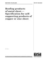
To better provide a comparison of the various exposure limits, developed in clause 4.3, including the
effects of the field-of-view, both a tabular and graphical summary are shown at the end of this clause.
Thus Figure 5.4 and Table 5.4 summarizes the maximum values for each of the irradiance based
hazard exposure quantities as a function of exposure time, while Figure 5.5 and Table 5.5 summarizes
the maximum radiance based (retinal) hazard exposure quantities, also as a function of exposure time.
Note:
The upper wavelength range for evaluation of any hazard is given as 3000 nm in clause 1.
Spectral irradiance or radiance measurements using a monochromator are often difficult to
make in the IR, particularly between 2500 and 3000 nm due to a lack of signal response and
difficulty in obtaining calibrated sources. However, no weighting function is defined at
wavelengths greater than 1400 nm. Thus broadband measurements for wavelengths between
1400 and 3000 nm are suitable in evaluating IR hazard conditions for the eye and skin in this
region.
5.1 Measurement conditions
Measurement conditions shall be reported as part of the evaluation against the exposure limits and the
assignment of risk classification.
5.1.1 Lamp ageing (seasoning)
To maintain stable output during the measurement process and provide reproducible results, lamps
shall be seasoned for an appropriate period of time. During the initial period of operation a lamp output
characteristic will change as its components come to near equilibrium. If measurements are taken of
an unseasoned lamp, the variations within the measurement period and between measurements could
be significant. As the output of a lamp generally decreases over life, the seasoning time should be
short to result in conservative hazard evaluations.
Seasoning of lamps shall be done as stated in the appropriate IEC lamp standard.
Note:
The seasoning time for discharge lamps, e.g., fluorescent or High Intensity Discharge (HID)
types, is typically 100 h, for tungsten lamps it is on the order of one percent of rated lamp life.
However, these seasoning criteria may differ for special applications, e.g. for solaria lamps.
BS EN 62471:2008
62471 © IEC:2006
– 16 –
5.1.2 Test environment
The accurate measurement of light sources requires a controlled environment. The operation of
sources and measurement equipment is impacted by environmental factors. Additionally the formation
of ozone in the measurement path may compromise accuracy and may present a safety hazard. For
specific test conditions, see the appropriate IEC lamp standard or in the absence of such standards,
the appropriate national standards or manufacturer’s recommendations.
The ambient temperature will significantly influence the output of certain light sources; e.g., fluorescent
lamps. The ambient temperature in which measurements are taken shall be maintained in accordance
with the appropriate IEC lamp standard.
The characteristics of some light sources are also significantly affected by draughts. Air movement
over the surface of test lamps, other than that caused by natural convection due to the lamp itself,
should be reduced as much as possible consistent with safety considerations (ozone production).
When the system under test provides interlocks that maintain circulation, measurements shall be
performed with circulation.
5.1.3 Extraneous radiation
Careful checks should be made to ensure that extraneous sources of radiation and reflections do not
add significantly to the measurement results. Often baffles are used to reduce extraneous radiation.
Note that visually black surfaces can be reflective to UV and IR radiation. In addition radiation from hot
baffles must be considered in infrared measurements due to the large input angle subtended by
baffles.
5.1.4 Lamp operation
Operation of the test lamp shall be provided in accordance with the appropriate IEC lamp standard. If
no standard for the lamp type exists, the lamp manufacturer’s recommendation for operation should be
used.
5.1.5 Lamp system operation
The power source for operation of the test lamp shall be provided in accordance with the appropriate
IEC standard. If no standard for the control gear exists, the lamp manufacturer’s recommendation for
operation should be used.
5.2 Measurement procedure
5.2.1 Irradiance measurements
The description given applies both to broadband and spectral irradiance measurements. An ideal
instrument to measure irradiance involves a plane circular area detector of diameter D, sufficient to
achieve the desired signal-to-noise ratio and, that:
•
•
•
accepts radiation within a right circular cone whose centerline is normal to the plane of the detector
area,
has an angular spatial response varying as the cosine of the angle from the normal to the detector
area,
has a spectral response that is constant with position within a specified wavelength band from λ1 to
λ2.
In this standard the minimum input aperture diameter shall be 7 mm with a maximum input aperture
diameter of 50 mm. A plane circular aperture of 25 mm diameter is common on small integrating
spheres, recommended above as the input for monochromators. The 25 mm diameter aperture is
recommended for sources with spatially uniform optical radiation patterns. For sources that do not
produce a spatially uniform irradiance, e.g., narrow beam reflector lamps, the peak irradiance
(intensity) may be significantly higher than that obtained by measurement using the under-filled 25 mm
diameter aperture. In such cases the detector aperture should be limited to a 7 mm diameter aperture.
62471 © IEC:2006
BS EN 62471:2008
– 17 –
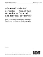
Figure 5.1 schematically shows the main concepts involved in making irradiance or spectral irradiance
measurements, including, if needed, the aperture to limit the field of view, of half angle, A, at some
distance from the receptor that is large with respect to the detector diameter.
The measurement shall be made in that position of the beam giving the maximum reading. The
instrument shall be calibrated to read in absolute incident radiant power per unit receiving area.
Note 1: From a practical point changing the input aperture requires significant extra work in recalibration of the radiometer or spectroradiometer. If the change of irradiance with distance is
known, one method of achieving the lower aperture requirement is to move the detector
aperture (assume 25 mm diameter is used) away from the source to a measurement distance
where the 7 mm aperture cone at a distance of 200 mm now fills the 25 mm aperture, i.e., a
distance about 3,5 times the standard evaluation distance.
Note 2: The measured irradiance should not be averaged over a smaller aperture than specified, as
this might result in an overestimation of the hazard. The minimum size of the averaging
aperture is related to physiological and behavioural factors that result in the averaging of the
incident radiation over a certain surface area.
Note 3: For a number of reasons, including the physiology of the eye, all the exposure levels for
ultraviolet radiation discussed in clause 4.3.1 and 4.3.2 apply to sources that subtend an angle
less than 80 degrees (1,4 radian), i.e., sources within 40 degrees of the normal to the
irradiance area. Thus emission from sources that subtend a greater angle need to be
measured only over a full angle of 80 degrees.
Irradiance measurements apply to the following hazards described in clause 4.3 of this standard.
•
•
•
315 nm – 400 nm ocular exposure limit, EUVA
IR hazard exposure limit, EIR
Skin – thermal hazard exposure limit, EH
Spectral irradiance measurements apply to the following hazards also described in clause 4.3 of this
standard.
•
•
200 – 400 nm skin and ocular exposure limit, ES
Retinal blue light hazard exposure limit – small source, EB
A
Aperture
to lim it
field of
view
H
Detector
H >> D
D
Figure 5.1 Schem atic - Irradiance measurements.
BS EN 62471:2008
62471 © IEC:2006
– 18 –
5.2.2 Radiance measurements
5.2.2.1 Standard method
The description given applies both to broadband and spectral radiance measurements. Radiance
measurements are performed with an optical system that (see Figure 5.2):
•
•
•
images the radiant source onto a detector,
has a circular field stop to establish the specified angular extent of the averaging field of view αeff,
has a circular entrance pupil (aperture stop) which acts as an averaging aperture in the sense of
irradiance measurements and fulfils the same requirements as stated in clause 5.2.1. For small
angles the relationship between the detector diameter and the focal distance of the imaging device
is seen to be d = αeff⋅H.
As with irradiance measurements, the minimum aperture stop diameter D, as shown in Figure 5.2,
corresponds to a 7 mm pupil diameter for pulsed sources and is a biophysically recognised averaging
aperture for cw sources where the pupil could be smaller but eye and head movements allow for this
aperture averaging. As with irradiance measurements, the aperture stop can exceed 7 mm if the
incident irradiance profile is sufficiently uniform.
H
D
Source
Detector/
Field Stop
d
α eff
α eff
Entrance and Exit
Pupils Coincident
Aperture Stop
Figure 5.2 Example of an imaging device for radiance measurements.
The instrument shall be calibrated to read in absolute incident radiant power per unit receiving area
and per unit solid angle of acceptance averaged over the field of view (FOV) of the instrument.
Note:
The measured radiance should not be averaged over a smaller field of view than specified, as
this might result in an overestimation of the hazard. The size of the averaging field of view is
related to the extent of eye movements that distribute the radiant power of the source image
over a larger area on the retina. The size of the averaging field of view αeff is independent of
the source size α. For sources that subtend an angle α smaller than the specified field of view
αeff, the averaged radiance value will be smaller than the actual physical radiance of the
source; however this biologically effective value is the appropriate value to be compared to the
exposure limit.
62471 © IEC:2006
BS EN 62471:2008
– 19 –
Spectral radiance measurements apply to the following hazards also described in clause 4.3 of this
standard.
•
•
•
Retinal blue light hazard exposure limit, LB
Retinal thermal exposure limit, LR
Retinal thermal exposure limit – weak visual stimulus, LIR.
5.2.2.2 Alternative method
Radiance measurements can be conceptualised as an irradiance measurement performed with a welldefined field of view where the measured irradiance value is divided by the measurement field of view
to obtain the radiance value. Alternatively to an imaging radiance set-up (above), an irradiance
measurement set-up with a circular field stop placed at the source can be used to perform radiance
measurements (Figure 5.3). The size of the field stop, F, and the distance of the field stop to the
aperture stop, r, define the field of view, i.e.:
γ = F/r
(5.1)
This set-up implies that the field stop can be placed sufficiently close to the apparent source to
produce the required field of view.
The relationship between the measured irradiance, E, and the source radiance, L, for detection normal
to the source area, (θ = 0 in definition 3.31), for small angles, is given as:
E = L⋅Ω ,
(5.2)
where Ω, angle in sr, is the measurement field of view, i.e., the solid angle subtended by the planar
angle, γ, angle in radian, shown in Figure 5.3. Furthermore, for small angles the relationship between
the plane angle γ and the solid angle Ω is:
Ω=
π ⋅γ 2
(5.3)
4
Thus using the dimensions shown in Figure 5.3, the irradiance in terms of the source radiance is given
by:
E = L⋅
π ⋅γ 2
4
= L⋅
π ⋅ F2
(5.4)
4⋅r2
Source
r
Detector/
Aperture Stop
D
γ
F
Field Stop
Figure 5.3 Alternative radiance technique.
BS EN 62471:2008
62471 © IEC:2006
– 20 –
When using the irradiance measurements to obtain radiance values to compare against a given
hazard, the field stop diameter, F, must be set such that
γ = αeff
Note:
(5.5)
The blue light hazard small-source-irradiance limit is equivalent to the radiance limit for the
specified measurement averaging field of view. The irradiance limit is derived by multiplying
the radiance limit with the averaging measurement field of view using Equation (5.4).
5.2.3 Measurement of source size
The determination of α, the angle subtended by a source, requires the determination of the 50%
emission points of the source. Common methods using photography or solid state cameras should be
used only after verifying that the spectral uniformity is sufficient to warrant the use of visible radiation
as an analog for the IR radiation. Changes in spectra across a source can lead to different sizes in
different regions of the spectra. (See Sliney and Wolbarsht, 1980, clause 12.6.6.)
5.2.4 Pulse width measurement for pulsed sources
The determination of ∆t, the nominal pulse duration of a source, requires the determination of the time
during which the emission is > 50% of its peak value. Common methods, e.g., using a photocell with
an oscilloscope, should be applied only after verifying that the spectral uniformity is sufficient to warrant
the use of visible radiation as an analog for the UV or IR radiation. Changes in spectra during a pulse
can lead to different pulse widths in different regions of the spectra.
5.3 Analysis methods
5.3.1 Weighting curve interpolations
The weighting curves defined in Table 4.1 are normally not sufficiently resolved to perform the
weighted source emission calculations. The functions are reasonably linear in any local region on
semi-log coordinates. Therefore to standardize interpolated values, use linear interpolation on the log
of given values to obtain intermediate points at the wavelength intervals desired, e.g., one nanometer
interval recommended. Anti-logarithm of the interpolated numbers result in the values needed for the
interpolated weighting factors.
5.3.2 Calculations
The calculation of source hazard values shall be performed by weighting the spectral scan by the
appropriate function and calculating the total weighted energy. To provide a repeatable method this
standard suggests interpolation or summing to one nanometer (1 nm) for the spectra below 400 nm.
Weighting and summations are then performed at this 1 nm resolution. Above 400 nm, a step size of 5
nm is recommended.
5.3.3 Measurement uncertainty
The quality of all measurement results must be quantified by an analysis of the uncertainty. All
calculated results must be paired with uncertainty values that conform to the guidance in the normative
references. The uncertainty of each result will be reported as the expanded uncertainty, which is
calculated from the combined standard uncertainty, uc , by use of a coverage factor, k=2, as defined in
the ISO guide listed in Clause 2. The values of uncertainty should be propagated from the calibration
uncertainties, through the calculations and include all sources as described in Annex C.
62471 © IEC:2006
BS EN 62471:2008
– 21 –
Table 5.4 Summary of the ELs for the surface of the skin or cornea (irradiance based values)
Hazard
Name
Relevant
equation
∑Eλ ⋅S(λ) ⋅ ∆λ
= ∑ E λ ⋅ ∆λ
Actinic UV
skin & eye
Es =
Eye UV-A
E UVA
Blue-light
EB =
small source
Eye IR
∑Eλ ⋅ B(λ) ⋅ ∆λ
∑ Eλ ⋅ ∆λ
= ∑ E ⋅ ∆λ
E IR =
Skin thermal E H
λ
EL in terms of
Wavelength Exposure Limiting
range
duration aperture constant irradiance
-2
nm
sec
rad (deg)
W⋅ m
200 – 400
315 – 400
300 – 700
780 –3000
380 – 3000
< 30000
≤1000
>1000
≤100
>100
≤1000
>1000
< 10
1,4 (80)
1,4 (80)
< 0,011
1,4 (80)
2π sr
30/t
10000/t
10
100/t
1,0
0,75
18000/t
100
20000/t
0,75
Table 5.5 Summary of the ELs for the retina (radiance based values)
Hazard
Name
Blue light
Relevant
equation
LB =
Wavelength Exposure
range
duration
nm
sec
Field of
view
radians
∑Lλ ⋅ B(λ) ⋅ ∆λ
300 – 700
0,25 – 10 0,011⋅√(t/10)
10-100
0,011
100-10000 0,0011⋅√t
≥ 10000
0,1
∑
380 – 1400
0,0017
< 0,25
0,25 – 10 0,011⋅√(t/10)
∑
780 – 1400
Retinal
LR = Lλ ⋅ R(λ) ⋅ ∆λ
thermal
Retinal
thermal
L = Lλ ⋅ R(λ) ⋅ ∆λ
(weak visual IR
stimulus)
> 10
0,011
EL in terms of
constant radiance
-2
-1
W⋅m ⋅sr )
6
10 /t
6
10 /t
6
10 /t
100
50000/(α⋅t )
0,25
50000/(α⋅t )
0,25
6000/α
BS EN 62471:2008
62471 © IEC:2006
– 22 –
1E+07
1E+06
Irradiance [Wm-2]
1E+05
1E+04
1E+03
1E+02
1E+01
1E+00
1E-01
1E-02
E Ss
E UVA
UVA
E BB
E IR
IR
1E-03
1E-03 1E-02 1E-01 1E+00 1E+01 1E+02 1E+03 1E+04 1E+05
Time [sec]
Figure 5.4 Weighted irradiance exposure limits vs. time
for constant exposure.
1E+09
Radiance [Wm -2sr-1]
1E+08
1E+07
1E+06
1E+05
L R_amin
R_amin
1E+04
LL R_amax
R_amax
1E+03
L BB
1E+02
L
L IR_amin
IR_amin
LL IR_amax
IR_amax
1E+01
1E-03 1E-02 1E-01 1E+00 1E+01 1E+02 1E+03 1E+04 1E+05
Time [sec]
Figure 5.5 Weighted radiance exposure limits vs. time
for constant exposure.
62471 © IEC:2006
– 23 –
BS EN 62471:2008
6. LAMP CLASSIFICATION
This standard was developed by CIE TC 6-47 with representation of IEC SC34A. This joint effort was
deemed important so that issues concerning risk group classification and distance at which the
photobiological hazard values due to lamp radiation are reported could be agreed upon. Since lamps
may be hazardous from several aspects, a classification scheme is helpful. For the purposes of this
standard it was decided that the values shall be reported as follows:
•
•
for lamps intended for general lighting service (GLS), see definition 3.11, the hazard values shall
be reported as either irradiance or radiance values at a distance which produces an illuminance of
500 lux, but not at a distance less than 200 mm;
for all other light sources, including pulsed lamp sources, the hazard values shall be reported at a
distance of 200 mm.
This clause is concerned with lamp classification. However a similar classification system could be
applicable to luminaires or other systems containing operating lamps. For lamps intended for general
lighting, the distance at which the irradiance measurements are made is left to the discretion of the
measurement facility.
The classification scheme indicates only the potential risk. Depending upon use factors, time of
exposure, and luminaire effects, these potential hazards may or may not actually become real hazards.
Table 6.1 summarizes the various irradiance and radiance emission limits for each of the hazards
discussed in clause 4.3 for each risk group classification.
Note:
In some cases the same lamp may be used in both GLS and special applications and in such
cases should be evaluated and rated for the intended applications.
6.1 Continuous wave lamps
6.1.1 Exempt group
The philosophical basis for the exempt group classification is that the lamp does not pose any
photobiological hazard for the end points in this standard. This requirement is met by any lamp that
does not pose
•
•
•
•
•
an actinic ultraviolet hazard (Es) within 8-hours exposure (30000 s), nor
a near-UV hazard (EUVA) within 1000 s, (about 16 min) nor
a retinal blue-light hazard (LB) within 10000 s (about 2,8 h), nor
a retinal thermal hazard (LR) within 10 s, nor
an infrared radiation hazard for the eye (EIR) within 1000 s.
These lamps are in the Exempt Group.
-2
Also, lamps that emit infrared radiation without a strong visual stimulus (i.e., less than 10 cd⋅m ) and
do not pose a near-infrared retinal hazard (LIR) within 1000 s are in the Exempt Group.
6.1.2 Risk Group 1 (Low-Risk)
The philosophical basis for this classification is that the lamp does not pose a hazard due to normal
behavioral limitations on exposure. This requirement is met by any lamp that exceeds the limits for the
Exempt Group but that does not pose
•
•
•
•
•
an actinic ultraviolet hazard (Es) within 10000 s, nor
a near ultraviolet hazard (EUVA) within 300 s, nor
a retinal blue-light hazard (LB) within 100 s, nor
a retinal thermal hazard (LR) within 10 s, nor
an infrared radiation hazard for the eye (EIR) within 100 s.
These lamps are in Risk Group 1 (Low-Risk).
-2
Also, lamps that emit infrared radiation without a strong visual stimulus (i.e., less than 10 cd⋅m ) and
do not pose a near-infrared retinal hazard (LIR), within 100 s are in Risk Group 1 (Low-Risk).