Iec 60728 1 1 2014
Bạn đang xem bản rút gọn của tài liệu. Xem và tải ngay bản đầy đủ của tài liệu tại đây (1.09 MB, 136 trang )
®
Edition 2.0 2014-03
INTERNATIONAL
STANDARD
NORME
INTERNATIONALE
colour
inside
Cable networks for television signals, sound signals and interactive services –
Part 1-1: RF cabling for two way home networks
IEC 60728-1-1:2014-03(en-fr)
Réseaux de distribution par câbles pour signaux de télévision, signaux de
radiodiffusion sonore et services interactifs –
Partie 1-1: Câblage RF pour réseaux domestiques bidirectionnels
Copyrighted material licensed to BR Demo by Thomson Reuters (Scientific), Inc., subscriptions.techstreet.com, downloaded on Nov-27-2014 by James Madison. No further reproduction or distribution is permitted. Uncontrolled when printe
IEC 60728-1-1
Copyright © 2014 IEC, Geneva, Switzerland
All rights reserved. Unless otherwise specified, no part of this publication may be reproduced or utilized in any form
or by any means, electronic or mechanical, including photocopying and microfilm, without permission in writing from
either IEC or IEC's member National Committee in the country of the requester. If you have any questions about IEC
copyright or have an enquiry about obtaining additional rights to this publication, please contact the address below or
your local IEC member National Committee for further information.
Droits de reproduction réservés. Sauf indication contraire, aucune partie de cette publication ne peut être reproduite
ni utilisée sous quelque forme que ce soit et par aucun procédé, électronique ou mécanique, y compris la photocopie
et les microfilms, sans l'accord écrit de l'IEC ou du Comité national de l'IEC du pays du demandeur. Si vous avez des
questions sur le copyright de l'IEC ou si vous désirez obtenir des droits supplémentaires sur cette publication, utilisez
les coordonnées ci-après ou contactez le Comité national de l'IEC de votre pays de résidence.
IEC Central Office
3, rue de Varembé
CH-1211 Geneva 20
Switzerland
Tel.: +41 22 919 02 11
Fax: +41 22 919 03 00
www.iec.ch
About the IEC
The International Electrotechnical Commission (IEC) is the leading global organization that prepares and publishes
International Standards for all electrical, electronic and related technologies.
About IEC publications
The technical content of IEC publications is kept under constant review by the IEC. Please make sure that you have the
latest edition, a corrigenda or an amendment might have been published.
IEC Catalogue - webstore.iec.ch/catalogue
The stand-alone application for consulting the entire
bibliographical information on IEC International Standards,
Technical Specifications, Technical Reports and other
documents. Available for PC, Mac OS, Android Tablets and
iPad.
Electropedia - www.electropedia.org
The world's leading online dictionary of electronic and
electrical terms containing more than 30 000 terms and
definitions in English and French, with equivalent terms in 14
additional languages. Also known as the International
Electrotechnical Vocabulary (IEV) online.
IEC publications search - www.iec.ch/searchpub
The advanced search enables to find IEC publications by a
variety of criteria (reference number, text, technical
committee,…). It also gives information on projects, replaced
and withdrawn publications.
IEC Glossary - std.iec.ch/glossary
More than 55 000 electrotechnical terminology entries in
English and French extracted from the Terms and Definitions
clause of IEC publications issued since 2002. Some entries
have been collected from earlier publications of IEC TC 37,
77, 86 and CISPR.
IEC Just Published - webstore.iec.ch/justpublished
Stay up to date on all new IEC publications. Just Published
details all new publications released. Available online and
also once a month by email.
IEC Customer Service Centre - webstore.iec.ch/csc
If you wish to give us your feedback on this publication or
need further assistance, please contact the Customer Service
Centre:
A propos de l'IEC
La Commission Electrotechnique Internationale (IEC) est la première organisation mondiale qui élabore et publie des
Normes internationales pour tout ce qui a trait à l'électricité, à l'électronique et aux technologies apparentées.
A propos des publications IEC
Le contenu technique des publications IEC est constamment revu. Veuillez vous assurer que vous possédez l’édition la
plus récente, un corrigendum ou amendement peut avoir été publié.
Catalogue IEC - webstore.iec.ch/catalogue
Application autonome pour consulter tous les renseignements
bibliographiques
sur
les
Normes
internationales,
Spécifications techniques, Rapports techniques et autres
documents de l'IEC. Disponible pour PC, Mac OS, tablettes
Android et iPad.
Recherche de publications IEC - www.iec.ch/searchpub
La recherche avancée permet de trouver des publications IEC
en utilisant différents critères (numéro de référence, texte,
comité d’études,…). Elle donne aussi des informations sur les
projets et les publications remplacées ou retirées.
IEC Just Published - webstore.iec.ch/justpublished
Restez informé sur les nouvelles publications IEC. Just
Published détaille les nouvelles publications parues.
Disponible en ligne et aussi une fois par mois par email.
Electropedia - www.electropedia.org
Le premier dictionnaire en ligne de termes électroniques et
électriques. Il contient plus de 30 000 termes et dộfinitions en
anglais et en franỗais, ainsi que les termes équivalents dans
14 langues additionnelles. Egalement appelé Vocabulaire
Electrotechnique International (IEV) en ligne.
Glossaire IEC - std.iec.ch/glossary
Plus de 55 000 entrées terminologiques électrotechniques, en
anglais et en franỗais, extraites des articles Termes et
Dộfinitions des publications IEC parues depuis 2002. Plus
certaines entrées antérieures extraites des publications des
CE 37, 77, 86 et CISPR de l'IEC.
Service Clients - webstore.iec.ch/csc
Si vous désirez nous donner des commentaires sur cette
publication ou si vous avez des questions contactez-nous:
Copyrighted material licensed to BR Demo by Thomson Reuters (Scientific), Inc., subscriptions.techstreet.com, downloaded on Nov-27-2014 by James Madison. No further reproduction or distribution is permitted. Uncontrolled when printe
THIS PUBLICATION IS COPYRIGHT PROTECTED
®
Edition 2.0 2014-03
INTERNATIONAL
STANDARD
NORME
INTERNATIONALE
colour
inside
Cable networks for television signals, sound signals and interactive services –
Part 1-1: RF cabling for two way home networks
Réseaux de distribution par câbles pour signaux de télévision, signaux de
radiodiffusion sonore et services interactifs –
Partie 1-1: Câblage RF pour réseaux domestiques bidirectionnels
INTERNATIONAL
ELECTROTECHNICAL
COMMISSION
COMMISSION
ELECTROTECHNIQUE
INTERNATIONALE
PRICE CODE
CODE PRIX
ICS 33.060.30; 33.160.01
XB
ISBN 978-2-8322-1437-4
Warning! Make sure that you obtained this publication from an authorized distributor.
Attention! Veuillez vous assurer que vous avez obtenu cette publication via un distributeur agréé.
® Registered trademark of the International Electrotechnical Commission
Marque déposée de la Commission Electrotechnique Internationale
Copyrighted material licensed to BR Demo by Thomson Reuters (Scientific), Inc., subscriptions.techstreet.com, downloaded on Nov-27-2014 by James Madison. No further reproduction or distribution is permitted. Uncontrolled when printe
IEC 60728-1-1
IEC 60728-1-1:2014 © IEC 2014
CONTENTS
FOREWORD ........................................................................................................................... 5
INTRODUCTION ..................................................................................................................... 7
1
Scope .............................................................................................................................. 9
2
Normative references ...................................................................................................... 9
3
Terms, definitions, symbols and abbreviations ............................................................... 11
4
3.1
Terms and definitions ....................................................................................... 11
3.2
Symbols ........................................................................................................... 19
3.3
Abbreviations ................................................................................................... 20
Methods of measurement for the home network ............................................................. 21
5
Performance requirements of the home network ............................................................ 22
5.1
5.2
5.3
6
General ............................................................................................................ 22
Impedance ....................................................................................................... 23
Performance requirements at the terminal input ............................................... 23
5.3.1
General .......................................................................................... 23
5.3.2
Signal level ..................................................................................... 23
5.3.3
Other parameters ........................................................................... 24
Performance requirements at system outlets .................................................... 24
5.4
5.4.1
Minimum and maximum carrier levels ............................................. 24
5.4.2
Mutual isolation between system outlets ......................................... 24
5.4.3
Isolation between individual outlets in one household ..................... 24
5.4.4
Isolation between forward and return path ...................................... 24
5.4.5
Long-term frequency stability of distributed carrier signals at
any system outlet............................................................................ 24
5.5
Performance requirements at the HNI .............................................................. 24
5.5.1
Minimum and maximum carrier levels at HNI1 ................................ 24
5.5.2
Minimum and maximum carrier levels at HNI2 and HNI3 ................. 24
Carrier level differences in the home network from HNI to system outlet .......... 24
5.6
5.7
Frequency response within a television channel in the home network .............. 25
5.7.1
General .......................................................................................... 25
5.7.2
Amplitude response ........................................................................ 25
5.7.3
Group delay .................................................................................... 25
Random noise produced in the home network .................................................. 26
5.8
5.9
Interference produced into downstream channels within a home network ......... 26
5.9.1
General .......................................................................................... 26
5.9.2
Multiple frequency intermodulation interference .............................. 26
5.9.3
Intermodulation noise ..................................................................... 27
5.9.4
Crossmodulation ............................................................................. 27
Home network design and examples .............................................................................. 27
6.1
6.2
6.3
General ............................................................................................................ 27
Basic design considerations ............................................................................. 27
6.2.1
General .......................................................................................... 27
6.2.2
System outlet (SO) or terminal input (TI) specifications................... 27
6.2.3
Home network interface (HNI) specifications ................................... 27
6.2.4
Requirements for the home network ............................................... 28
Implementation considerations ......................................................................... 28
Copyrighted material licensed to BR Demo by Thomson Reuters (Scientific), Inc., subscriptions.techstreet.com, downloaded on Nov-27-2014 by James Madison. No further reproduction or distribution is permitted. Uncontrolled when printe
–2–
–3–
6.4
Home networks with coaxial and balanced cables ............................................ 29
6.4.1
General .......................................................................................... 29
6.4.2
Network examples .......................................................................... 29
6.4.3
Calculation examples ...................................................................... 30
6.4.4
General considerations ................................................................... 40
6.4.5
Home network design in a MATV system ........................................ 41
6.4.6
Return path examples ..................................................................... 41
Different home network types (HNI3 case C) (glass or plastic fibre optic
6.5
network) ........................................................................................................... 41
6.6
Different home network type (HNI3 case D) ..................................................... 42
6.6.1
General .......................................................................................... 42
6.6.2
Wireless links inside the home network ........................................... 42
6.6.3
Applications of IEEE 802.11 (WLAN) .............................................. 43
6.6.4
Available bands in the 2 GHz to 6 GHz frequency range ................. 44
6.6.5
Main characteristics of a WLAN signal ............................................ 44
6.6.6
Main characteristics of coaxial cables ............................................. 45
6.6.7
Characteristics of WLAN signals at system outlet ........................... 45
6.6.8
Characteristics of signals at the TV system outlet ........................... 46
6.6.9
Example of diplexers and power splitters near the HNI ................... 46
6.6.10
Example of system outlet for coaxial TV connector and WLAN
antenna .......................................................................................... 46
6.6.11
Examples of WLAN connection into home networks ........................ 47
Annex A (informative) Wireless links versus cable links ....................................................... 52
General ............................................................................................................ 52
A.1
A.2
Wireless links................................................................................................... 52
A.3
Cable links ....................................................................................................... 53
Annex B (informative) Isolation between radiating element and system outlet ...................... 55
Annex C (informative) MIMO techniques of IEEE 802.11n .................................................... 57
General ............................................................................................................ 57
C.1
C.2
MIMO techniques ............................................................................................. 57
Bibliography .......................................................................................................................... 59
Figure 1 – Examples of RF home network types ..................................................................... 8
Figure 2 – Examples of location of HNI for various home network types ................................ 15
Figure 3 – Examples of home network implementation using coaxial or balanced
cables ................................................................................................................................... 30
Figure 4 – Signal levels at HNI1 (flat splitter response) ......................................................... 32
Figure 5 – Signal levels at HNI1 (+6 dB compensating splitter slope) .................................... 33
Figure 6 – Signal levels at HNI2 (L 1 ) (flat splitter/amplifier response) ................................... 34
Figure 7 – Signal levels at HNI2 (+6 dB compensating splitter/amplifier slope) ..................... 34
Figure 8 – Signal levels at HNI3 (flat splitter/amplifier response) .......................................... 38
Figure 9 – Signal levels at HNI3 (+6 dB compensating splitter/amplifier slope) ..................... 38
Figure 10 – Example of a home network using optical fibres ................................................. 41
Figure 11 – Example of a home network using cable connection and cable/wireless
connection ............................................................................................................................ 43
Figure 12 – Example of a coupler (tandem coupler) to insert WLAN signals into the
home distribution network ..................................................................................................... 46
Figure 13 – Example of system outlet for coaxial TV connector and WLAN antenna .............. 46
Copyrighted material licensed to BR Demo by Thomson Reuters (Scientific), Inc., subscriptions.techstreet.com, downloaded on Nov-27-2014 by James Madison. No further reproduction or distribution is permitted. Uncontrolled when printe
IEC 60728-1-1:2014 © IEC 2014
IEC 60728-1-1:2014 © IEC 2014
Figure 14 – Assumed properties of the filters in the system outlet ......................................... 47
Figure 15 – Reference points for the examples of calculation of link loss or link budget ........ 47
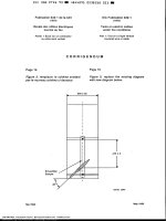
Figure B.1 – Required isolation and attenuation of a cut-off waveguide, with cut-off
frequency of 2 275 MHz and a length (L) of 25 cm or 15 cm .................................................. 55
Figure C.1 – Principle of MIMO techniques according to IEEE 802.11n ................................. 57
Table 1 – Methods of measurement of IEC 60728-1:2014 applicable to the home
network ................................................................................................................................. 22
Table 2 – Amplitude response variation in the home network ................................................ 25
Table 3 – Group delay variation in the home network ............................................................ 26
Table 4 – Example of home network implementation with coaxial cabling (passive) from
HNI1 to system outlet ........................................................................................................... 35
Table 5 – Example of home network implementation with coaxial cabling (active) from
HNI2 to system outlet ........................................................................................................... 35
Table 6 – Example of home network implementation with balanced pair cables (active)
from HNI3 to coaxial terminal input (case A) ......................................................................... 39
Table 7 – Example of home network implementation with balanced pair cables (active)
from HNI3 to coaxial system outlet (case B) .......................................................................... 39
Table 8 – Maximum EIRP according to CEPT ERC 70-03 ..................................................... 44
Table 9 – Available throughput of the WLAN signal ............................................................... 45
Table 10 – Minimum signal level at system outlet (WLAN antenna) ....................................... 45
Table 11 – Loss from the system outlet to WLAN base station .............................................. 48
Table 12 – Direct connection between two system outlets (TV outlets) .................................. 49
Table 13 – Link budget between a WLAN equipment and the WLAN base station ................. 49
Table 14 – Wireless connection between two WLAN equipment ............................................ 50
Table 15 – Connection from a SO to a WLAN equipment ...................................................... 51
Table A.1 – Maximum distance for a wireless link (WLAN) in free space or inside a
home .................................................................................................................................... 53
Table A.2 – Maximum length of the cable.............................................................................. 54
Table C.1 – MCSs that are mandatory in IEEE 802.11n ........................................................ 58
Copyrighted material licensed to BR Demo by Thomson Reuters (Scientific), Inc., subscriptions.techstreet.com, downloaded on Nov-27-2014 by James Madison. No further reproduction or distribution is permitted. Uncontrolled when printe
–4–
–5–
INTERNATIONAL ELECTROTECHNICAL COMMISSION
____________
CABLE NETWORKS FOR TELEVISION SIGNALS,
SOUND SIGNALS AND INTERACTIVE SERVICES –
Part 1-1: RF cabling for two way home networks
FOREWORD
1) The International Electrotechnical Commission (IEC) is a worldwide organization for standardization comprising
all national electrotechnical committees (IEC National Committees). The object of IEC is to promote
international co-operation on all questions concerning standardization in the electrical and electronic fields. To
this end and in addition to other activities, IEC publishes International Standards, Technical Specifications,
Technical Reports, Publicly Available Specifications (PAS) and Guides (hereafter referred to as “IEC
Publication(s)”). Their preparation is entrusted to technical committees; any IEC National Committee interested
in the subject dealt with may participate in this preparatory work. International, governmental and nongovernmental organizations liaising with the IEC also participate in this preparation. IEC collaborates closely
with the International Organization for Standardization (ISO) in accordance with conditions determined by
agreement between the two organizations.
2) The formal decisions or agreements of IEC on technical matters express, as nearly as possible, an international
consensus of opinion on the relevant subjects since each technical committee has representation from all
interested IEC National Committees.
3) IEC Publications have the form of recommendations for international use and are accepted by IEC National
Committees in that sense. While all reasonable efforts are made to ensure that the technical content of IEC
Publications is accurate, IEC cannot be held responsible for the way in which they are used or for any
misinterpretation by any end user.
4) In order to promote international uniformity, IEC National Committees undertake to apply IEC Publications
transparently to the maximum extent possible in their national and regional publications. Any divergence
between any IEC Publication and the corresponding national or regional publication shall be clearly indicated in
the latter.
5) IEC itself does not provide any attestation of conformity. Independent certification bodies provide conformity
assessment services and, in some areas, access to IEC marks of conformity. IEC is not responsible for any
services carried out by independent certification bodies.
6) All users should ensure that they have the latest edition of this publication.
7) No liability shall attach to IEC or its directors, employees, servants or agents including individual experts and
members of its technical committees and IEC National Committees for any personal injury, property damage or
other damage of any nature whatsoever, whether direct or indirect, or for costs (including legal fees) and
expenses arising out of the publication, use of, or reliance upon, this IEC Publication or any other IEC
Publications.
8) Attention is drawn to the Normative references cited in this publication. Use of the referenced publications is
indispensable for the correct application of this publication.
9) Attention is drawn to the possibility that some of the elements of this IEC Publication may be the subject of
patent rights. IEC shall not be held responsible for identifying any or all such patent rights.
International Standard IEC 60728-1-1 has been prepared by technical area 5: Cable networks
for television signals, sound signals and interactive services, of IEC technical committee 100:
Audio, video and multimedia systems and equipment.
This second edition cancels and replaces the first edition published in 2010, and constitutes a
technical revision.
This edition includes the following significant technical changes with respect to the previous
edition:
•
update of performance requirements in Clause 5 to include those for DVB-T2 signals.
This International Standard is to be used in conjunction with IEC 60728-1:2014.
Copyrighted material licensed to BR Demo by Thomson Reuters (Scientific), Inc., subscriptions.techstreet.com, downloaded on Nov-27-2014 by James Madison. No further reproduction or distribution is permitted. Uncontrolled when printe
IEC 60728-1-1:2014 © IEC 2014
IEC 60728-1-1:2014 © IEC 2014
The text of this standard is based on the following documents:
FDIS
Report on voting
100/2249/FDIS
100/2285/RVD
Full information on the voting for the approval of this standard can be found in the report on
voting indicated in the above table.
This publication has been drafted in accordance with the ISO/IEC Directives, Part 2.
A list of all parts of the IEC 60728 series, under the general title Cable networks for television
signals, sound signals and interactive services, can be found on the IEC website.
The committee has decided that the contents of this publication will remain unchanged until
the stability date indicated on the IEC web site under "" in the data
related to the specific publication. At this date, the publication will be
•
reconfirmed,
•
withdrawn,
•
replaced by a revised edition, or
•
amended.
IMPORTANT – The 'colour inside' logo on the cover page of this publication indicates
that it contains colours which are considered to be useful for the correct
understanding of its contents. Users should therefore print this document using a
colour printer.
Copyrighted material licensed to BR Demo by Thomson Reuters (Scientific), Inc., subscriptions.techstreet.com, downloaded on Nov-27-2014 by James Madison. No further reproduction or distribution is permitted. Uncontrolled when printe
–6–
–7–
INTRODUCTION
Standards and deliverables of IEC 60728 series deal with cable networks including equipment
and associated methods of measurement for headend reception, processing and distribution
of television and sound signals and for processing, interfacing and transmitting all kinds of
data signals for interactive services using all applicable transmission media. These signals
are typically transmitted in networks by frequency-multiplexing techniques.
This includes for instance
•
regional and local broadband cable networks,
•
extended satellite and terrestrial television distribution systems,
•
individual satellite and terrestrial television receiving systems,
and all kinds of equipment, systems and installations used in such cable networks, distribution
and receiving systems.
The extent of this standardization work is from the antennas and/or special signal source
inputs to the headend or other interface points to the network up to the terminal input of the
customer premises equipment.
The standardization work will consider coexistence with users of the RF spectrum in wired
and wireless transmission systems.
The standardization of any user terminals (i.e. tuners, receivers, decoders, multimedia
terminals, etc.) as well as of any coaxial, balanced and optical cables and accessories thereof
is excluded.
The reception of television signals inside a building requires an outdoor antenna and a
distribution network to convey the signal to the TV receivers.
This part of the IEC 60728 deals with the requirements and implementation guidelines for a
home network that can be realised with different techniques. The following types of home
networks (HN) are possible:
•
passive coaxial home network;
•
active coaxial home network;
•
different home network types.
Figure 1 shows typical situations that are possible when considering RF home networks.
The RF home network can be realised using coaxial cables, balanced cables, optical cables
or radio links.
Clause 5 defines the performance limits measured at system outlet or terminal input for an
unimpaired (ideal) test signal applied at the HNI. Under normal operating conditions for any
analogue channel and meeting these limits, the cumulative effect of the impairment of any
single parameter at the HNI and that, due to the home network, will produce picture and
sound signals not worse than grade four on the five-grade impairment scale contained in
ITU-R BT.500. These requirements are given in IEC 60728-1-2. For digitally modulated
signals the quality requirement is a QEF (Quasi Error Free) reception.
This standard describes the physical layer connection for home networks. Description of
protocols required for Layer 2 and higher layers is out of the scope of this standard. Logical
connections between devices within the home network are therefore not always guaranteed.
Copyrighted material licensed to BR Demo by Thomson Reuters (Scientific), Inc., subscriptions.techstreet.com, downloaded on Nov-27-2014 by James Madison. No further reproduction or distribution is permitted. Uncontrolled when printe
IEC 60728-1-1:2014 © IEC 2014
IEC
Figure 1 – Examples of RF home network types
2523/09
Copyrighted material licensed to BR Demo by Thomson Reuters (Scientific), Inc., subscriptions.techstreet.com, downloaded on Nov-27-2014 by James Madison. No further reproduction or distribution is permitted. Uncontrolled when printe
IEC 60728-1-1:2014 © IEC 2014
–8–
–9–
CABLE NETWORKS FOR TELEVISION SIGNALS,
SOUND SIGNALS AND INTERACTIVE SERVICES –
Part 1-1: RF cabling for two way home networks
1
Scope
This part of IEC 60728 provides the requirements and describes the implementation
guidelines of RF cabling for two-way home networks. This standard is applicable to any home
network that distributes signals provided by CATV/MATV/SMATV cable networks (including
individual receiving systems) having a coaxial cable output. This standard also applies to
home networks where some part of the distribution network uses wireless links, for example
instead of the receiver cord.
This part of IEC 60728 is therefore applicable to RF cabling for two-way home networks with
wired cords or wireless links inside a room and primarily intended for television and sound
signals operating between about 5 MHz and 3 000 MHz. The frequency range is extended to
6 000 MHz for distribution techniques that replace wired cords with a wireless two-way
communication inside a room (or a small number of adjacent rooms) that uses the 5 GHz to
6 GHz band.
2
Normative references
The following documents, in whole or in part, are normatively referenced in this document and
are indispensable for its application. For dated references, only the edition cited applies. For
undated references, the latest edition of the referenced document (including any
amendments) applies.
IEC 60050-705,
propagation
International Electrotechnical Vocabulary – Chapter 705: Radio wave
IEC 60050-712,
International Electrotechnical Vocabulary – Chapter 712: Antennas
IEC 60050-725, International
radiocommunications
Electrotechnical
Vocabulary
–
Chapter
725:
Space
IEC 60728-1:2014, Cable networks for television signals, sound signals and interactive
services – Part 1: System performance of forward paths
IEC 60728-1-2, Cable networks for television signals, sound signals and interactive services
– Part 1-2: Performance requirements for signals delivered at system outlet in operation
IEC 60728-3:2010, Cable networks for television signals, sound signals and interactive
services – Part 3: Active wideband equipment for coaxial cable networks
IEC 60728-10, Cable networks for television signals, sound signals and interactive services
– Part 10: System performance of return paths
IEC 60966 (all parts),
Radio frequency and coaxial cable assemblies
IEC 60966-2 (all parts), Radio frequency and coaxial cable assemblies – Part 2: Detail
specification for cable assemblies for radio and TV receivers
Copyrighted material licensed to BR Demo by Thomson Reuters (Scientific), Inc., subscriptions.techstreet.com, downloaded on Nov-27-2014 by James Madison. No further reproduction or distribution is permitted. Uncontrolled when printe
IEC 60728-1-1:2014 © IEC 2014
IEC 60728-1-1:2014 © IEC 2014
IEC 60966-2-4, Radio frequency and coaxial cable assemblies – Part 2-4: Detail
specification for cable assemblies for radio and TV receivers – Frequency range 0 MHz to
3 000 MHz, IEC 61169-2 connectors
IEC 60966-2-5, Radio frequency and coaxial cable assemblies – Part 2-5: Detail
specification for cable assemblies for radio and TV receivers – Frequency range 0 MHz to
1 000 MHz, IEC 61169-2 connectors
IEC 60966-2-6, Radio frequency and coaxial cable assemblies – Part 2-6: Detail
specification for cable assemblies for radio and TV receivers – Frequency range 0 MHz to
3 000 MHz, IEC 61169-24 connectors
IEEE 802.11, IEEE Standards for Information technology – Telecommunications and
Information Exchange between Systems – Local and Metropolitan Area Network – Specific
Requirements – Part 11: Wireless LAN Medium Access Control (MAC) and Physical Layer
(PHY) Specifications 1I
IEEE 802.11a, IEEE Standard for Information technology – Telecommunications and
information exchange between systems – Local and metropolitan area networks – Specific
requirements – Part 11: Wireless LAN Medium Access Control (MAC) and Physical Layer
(PHY) specifications – Amendment 1: High-speed Physical Layer in the 5 GHz band
IEEE 802.11b, Supplement to 802.11-1999, Wireless LAN MAC and PHY specifications:
Higher speed Physical Layer (PHY) extension in the 2.4 GHz band
IEEE 802.11e, IEEE Standard for Information technology – Telecommunications and
information exchange between systems – Local and metropolitan area networks – Specific
requirements Part 11: Wireless LAN Medium Access Control (MAC) and Physical Layer (PHY)
specifications: Amendment 8: Medium Access Control (MAC) Quality of Service
Enhancements
IEEE 802.11g, IEEE Standard for Information technology – Telecommunications and
information exchange between systems – Local and metropolitan area networks – Specific
requirements – Part 11: Wireless LAN Medium Access Control (MAC) and Physical Layer
(PHY) specifications – Amendment 4: Further Higher-Speed Physical Layer Extension in the
2.4 GHz Band
IEEE 802.11h, IEEE Standard for Information technology – Telecommunications and
Information Exchange Between Systems – LAN/MAN Specific Requirements – Part 11:
Wireless LAN Medium Access Control (MAC) and Physical Layer (PHY) Specifications:
Spectrum and Transmit Power Management Extensions in the 5GHz band in Europe
IEEE 802.11n, IEEE Standard for Information Technology – Telecommunications and
information exchange between systems-Local and metropolitan area networks-Specific
requirements – Part 11: Wireless LAN Medium Access Control (MAC) and Physical Layer
(PHY) specifications: Amendment 4: Enhancements for Higher Throughput
IEEE 802.16, IEEE Standard for Local and metropolitan area networks – Part 16: Air
Interface for Fixed Broadband Wireless Access Systems (WiMax)
ITU-R Recommendation BT.500,
television pictures
Methodology for the subjective assessment of the quality of
—————————
1
Parts of IEEE 802.11 are reproduced in ISO/IEC 8802-11:2005, Information technology – Telecommunications
and information exchange between systems – Local and metropolitan area networks – Specific requirements –
Part 11: Wireless LAN Medium Access Control (MAC) and Physical Layer (PHY) specification
Copyrighted material licensed to BR Demo by Thomson Reuters (Scientific), Inc., subscriptions.techstreet.com, downloaded on Nov-27-2014 by James Madison. No further reproduction or distribution is permitted. Uncontrolled when printe
– 10 –
– 11 –
ITU-T Recommendation J.61, Transmission performance of television circuits designed for
use in international connections
ITU-T Recommendation J.63, Insertion of test signals in the field-blanking interval of
monochrome and colour television signals
EN 50117-2-4, Coaxial cables – Part 2-4: Sectional specification for cables used in cabled
distribution networks – Indoor drop cables for systems operating at 5 MHz to 3 000 MHz
ETSI EN 300 421, Digital Video Broadcasting (DVB); Framing structure, channel coding and
modulation for 11/12 GHz satellite services
ETSI EN 300 429, Digital Video Broadcasting (DVB); Framing structure, channel coding and
modulation for cable systems
ETSI EN 300 473, Digital Video Broadcasting (DVB); Satellite Master Antenna Television
(SMATV) distribution systems
ETSI EN 300 744, Digital Video Broadcasting (DVB); Framing structure, channel coding and
modulation for digital terrestrial television
ETSI EN 302 307, Digital Video Broadcasting (DVB) – Second generation framing structure,
channel coding and modulation systems for Broadcasting, Interactive Services, News
Gathering and other broadband satellite applications (DVB-S2)
ETSI EN 302 755, Digital Video Broadcasting (DVB) – Frame structure, channel coding and
modulation for a second generation digital terrestrial television broadcasting system (DVB-T2)
3
Terms, definitions, symbols and abbreviations
3.1
Terms and definitions
For the purposes of this document, the terms and definitions given in IEC 60050-705,
IEC 60050-712 and IEC 60050-725, apply.
NOTE
The most important definitions are repeated below.
3.1.1
active home network
home network that uses active equipment (for example, amplifiers) in addition to passive
equipment like splitters, taps, system outlets, cables and connectors up to the coaxial RF
interface (input and/or output) of the terminal equipment for distributing and combining RF
signals
3.1.2
antenna
part of a radio transmitting or receiving system which is designed to provide the required
coupling between a transmitter or receiver and the medium in which the radio wave
propagates
Note 1 to entry: In practice, the terminals of the antenna or the points to be considered as the interface between
the antenna and the transmitter or receiver should be specified.
Note 2 to entry: If the transmitter or receiver is connected to its antenna by a feeder line, the antenna may be
considered to be a transducer between the guided radio waves of the feeder line and the radiated waves in space.
[SOURCE: IEC 60050-712:1992, 712-01-01, modified – The term feeder line instead of feed
line has been used in note 2.]
Copyrighted material licensed to BR Demo by Thomson Reuters (Scientific), Inc., subscriptions.techstreet.com, downloaded on Nov-27-2014 by James Madison. No further reproduction or distribution is permitted. Uncontrolled when printe
IEC 60728-1-1:2014 © IEC 2014
IEC 60728-1-1:2014 © IEC 2014
3.1.3
attenuation
ratio of the input power to the output power of an equipment or system
Note 1 to entry:
The ratio is expressed in decibels.
3.1.4
balun
device for transforming an unbalanced voltage to a balanced voltage or vice-versa
Note 1 to entry:
The term is derived from balanced to unbalanced transformer.
3.1.5
bit error ratio
BER
ratio between erroneous bits and the total number of transmitted bits
3.1.6
broadcast and communication technologies
BCT
group of applications including RF distribution of sound signals and video signals
Note 1 to entry: For this standard, this is a group of applications using the HF band (3 MHz to 30 MHz), the VHF
band (30 MHz to 300 MHz) and the UHF band (300 MHz to 3 000 MHz) for transmission of television signals,
sound signals and interactive services, as well as for in-home inter-networking.
3.1.7
carrier-to-intermodulation ratio
C/I
difference between the carrier level at a specified point in a piece of equipment or a system
and the level of a specified intermodulation product or combination of products
Note 1 to entry: The difference is given in decibels.
3.1.8
carrier-to-noise ratio
C/N
difference between the vision or sound carrier level at a given point in a piece of equipment or
a system and the noise level at that point (measured within a bandwidth appropriate to the
television or radio system in use)
Note 1 to entry: The difference is given in decibels.
3.1.9
CATV network
regional and local broadband cable networks designed to provide sound and television signals
as well as signals for interactive services to a regional or local area
Note 1 to entry:
Originally defined as Community Antenna Television network.
3.1.10
cross-modulation
undesired modulation of the carrier of a desired signal by the modulation of another signal as
a result of equipment or system non-linearities
3.1.11
decibel ratio
ten times the logarithm to base 10 of the ratio of two quantities of power P 1 and P 2 , i.e
Copyrighted material licensed to BR Demo by Thomson Reuters (Scientific), Inc., subscriptions.techstreet.com, downloaded on Nov-27-2014 by James Madison. No further reproduction or distribution is permitted. Uncontrolled when printe
– 12 –
– 13 –
10 lg
Note 1 to entry:
P1
P2
in dB
May also be expressed in terms of voltages.
20 lg
U1
U2
in dB
3.1.12
designed receiving antenna
antenna that has the gain, the directivity and the polarization for receiving the wanted signal
at the headend site with the required performance
3.1.13
directivity
attenuation between output port and interface or tap port minus the attenuation between input
port and interface or tap port, of any equipment or system
3.1.14
DOCSIS
Euro-DOCSIS
standards defining interface specifications for cable modems and cable modem termination
systems for high-speed data communication over RF cable networks
3.1.15
dwelling unit
DU
home or office where television and sound signals are distributed and that provides access to
interactive services
3.1.16
echo rating
E
result of a system test with a 2T sine-squared pulse using the boundary line on a specified
graticule within which all parts of the received pulse fall
EXAMPLE
See Figure 25 of IEC 60728-1:2014.
Note 1 to entry:
Echo rating is determined in ITU-T Recommendation J.61 and ITU-T Recommendation J.63.
Note 2 to entry: The object of the graticule design is to ensure that the subjective effect of an echo of rating E %
is the same as that of a single echo, with displacement greater than 12T, of (E/2) % relative to the peak amplitude
of the test pulse.
3.1.17
extended satellite television distribution network or system
distribution network or system designed to provide sound and television signals received by
satellite receiving antenna to households in one or more buildings
Note 1 to entry: This kind of network or system can be combined with terrestrial antennas for the additional
reception of TV and/or radio signals via terrestrial networks.
Note 2 to entry: This kind of network or system can also carry control signals for satellite switched systems or
other signals for special transmission systems (e.g. MoCA or WiFi) in the return path direction.
3.1.18
extended terrestrial television distribution network or system
distribution network or system designed to provide sound and television signals received by
terrestrial receiving antennas to households in one or more buildings
Copyrighted material licensed to BR Demo by Thomson Reuters (Scientific), Inc., subscriptions.techstreet.com, downloaded on Nov-27-2014 by James Madison. No further reproduction or distribution is permitted. Uncontrolled when printe
IEC 60728-1-1:2014 © IEC 2014
IEC 60728-1-1:2014 © IEC 2014
Note 1 to entry: This kind of network or system can be combined with a satellite antenna for the additional
reception of TV and/or radio signals via satellite networks.
Note 2 to entry: This kind of network or system can also carry other signals for special transmission systems (e.g.
MoCA or WiFi) in the return path direction.
3.1.19
feeder
transmission path forming part of a cable network
Note 1 to entry:
Such a path may consist of a metallic cable, optical fibre, waveguide, or any combination of them.
Note 2 to entry:
By extension, the term is also applied to paths containing one or more radio links.
3.1.20
gain
ratio of the output power to the input power of any equipment or system
Note 1 to entry:
The ratio is expressed in decibels.
3.1.21
headend
equipment which is connected between receiving antennas or other signal sources and the
remainder of the cable networks, to process the signals to be distributed
Note 1 to entry: The headend may, for example, comprise antenna amplifiers, frequency converters, combiners,
separators and generators.
3.1.22
headend for individual reception
headend supplying an individual household
Note 1 to entry:
This type of installation may include one or more system outlets.
3.1.23
headend input
interface of the headend where the signals received by antennas or individual feeder lines are
applied for signal processing
3.1.24
home cable link
HCL
physical link (cable) between the home distributor (HD) and the system outlet or the terminal
input
3.1.25
home distributor
HD
distributor within a home where cables terminate
3.1.26
home network
HN
RF cable network inside a single dwelling (one-family house or one unit of a multi-dwelling
building) in the SOHO (Small Offices Home Offices) environments or in the rooms of hotels,
and hospitals.
Note 1 to entry:
The preferred topology of this network is a star.
Note 2 to entry: This network carries television signals, sound signals and interactive services up to the coaxial
RF interface (input and/or output) of the terminal equipment. It may comprise active equipment, passive equipment,
cables and connectors.
Copyrighted material licensed to BR Demo by Thomson Reuters (Scientific), Inc., subscriptions.techstreet.com, downloaded on Nov-27-2014 by James Madison. No further reproduction or distribution is permitted. Uncontrolled when printe
– 14 –
– 15 –
3.1.27
home network interface
HNI
interface for access to the network for transmission of television signals, sound signals and
interactive services inside a home (single dwelling)
Note 1 to entry:
Figure 2).
It is the first accessible point after the entrance of the network into an individual home (see
Note 2 to entry: In some cases the home network interface may coincide with the system outlet. In this case the
performance requirements for a system outlet apply.
Active home network
HNI
Passive home network
HNI
Looped system
outlets
HNI
Single
system
outlet
BNI
IEC 1013/09
Figure 2 – Examples of location of HNI for various home network types
3.1.28
individual satellite television receiving system
system designed to provide sound and television signals received from satellite(s) to an
individual household
Note 1 to entry: This kind of system can also carry control signals for satellite switched systems or other signals
for special transmission systems (e.g. MoCA or WiFi) in the return path direction.
3.1.29
individual terrestrial television receiving system
system designed to provide sound and television signals received via terrestrial broadcast
networks to an individual household
Note 1 to entry: This kind of system can also carry other signals for special transmission systems (e.g. MoCA or
WiFi) in the return path direction.
3.1.30
intermodulation
process whereby non-linearity of equipment in a system produces output signals (called
intermodulation products) at frequencies which are linear combinations of those of the input
signals
Copyrighted material licensed to BR Demo by Thomson Reuters (Scientific), Inc., subscriptions.techstreet.com, downloaded on Nov-27-2014 by James Madison. No further reproduction or distribution is permitted. Uncontrolled when printe
IEC 60728-1-1:2014 © IEC 2014
IEC 60728-1-1:2014 © IEC 2014
3.1.31
isolation
attenuation between two output, tap or interface ports of any equipment or system
3.1.32
3.1.32.1
level
ratio of any power P 1 to the standard reference power P 0 , i.e
10 lg
Note 1 to entry:
P1
P0
in dB
The ratio is given in decibel (dB).
Note 2 to entry: This may be expressed in decibels (relative to 1 µV in 75 Ω) or more simply in dB(µV) if there is
no risk of ambiguity.
3.1.32.2
level
ratio of any voltage U 1 to the standard reference voltage U 0 , i.e
20 lg
Note 1 to entry:
U1
U0
in dB
The ratio is given in decibel (dB).
Note 2 to entry: This may be expressed in decibels (relative to 1 µV in 75 Ω) or more simply in dB(µV) if there is
no risk of ambiguity.
3.1.33
local broadband cable network
network designed to provide sound and television signals as well as signals for interactive
services to a local area (e.g. one town or one village)
3.1.34
looped system outlet
device through which the spur feeder passes and to which is connected a receiver lead,
without the use of a subscriber feeder
3.1.35
MATV headend
headend used in blocks of flats and in built-up sites to feed TV channels and FM radio
channels into the house network or the spur network
3.1.36
MATV network
extended terrestrial television distribution networks or systems designed to provide sound and
television signals received by terrestrial receiving antenna to households in one or more
buildings
Note 1 to entry:
Originally defined as Master Antenna Television network.
Note 2 to entry: This kind of network or system can be combined with a satellite antenna for the additional
reception of TV and/or radio signals via satellite networks.
Note 3 to entry: This kind of network or system can also carry other signals for special transmission systems (e.g.
MoCA or WiFi) in the return path direction.
Copyrighted material licensed to BR Demo by Thomson Reuters (Scientific), Inc., subscriptions.techstreet.com, downloaded on Nov-27-2014 by James Madison. No further reproduction or distribution is permitted. Uncontrolled when printe
– 16 –
– 17 –
3.1.37
multi dwelling unit
MDU
building with many homes or offices used by single owners where television signals, sound
signals are distributed and with access to interactive services
3.1.38
multiplex
signals from several separate sources assembled into a single composite signal for
transmission over a common transmission channel
[SOURCE: IEC 60050-701:1988, 701-03-10, modified – Term and definition have been
changed to describe the result of the multiplexing process.]
3.1.39
mutual isolation
attenuation between two specified system outlets at any frequency within the range of the
system under investigation which is always specified, for any particular installation, as the
minimum value obtained within specified frequency limits
3.1.40
network interface
NI
interface to the network for transmission of television signals, sound signals and interactive
services
3.1.41
network termination unit
NTU
equipment for access to the cable network for television signals, sound signals and interactive
services
3.1.42
permanent link
transmission path between any two test interfaces within a cabling subsystem link including
the connecting hardware at each end
3.1.43
receiver lead
lead which connects the system outlet to the subscriber’s equipment
Note 1 to entry:
A receiver lead may include filters and balun transformers in addition to the cable.
3.1.44
regional broadband cable network
network designed to provide sound and television signals as well as signals for interactive
services to a regional area covering several towns and/or villages
3.1.45
SMATV network
extended distribution networks or systems designed to provide sound and television signals
received by satellite receiving antenna to households in one or more buildings
Note 1 to entry:
Originally defined as satellite master antenna television network.
Note 2 to entry: This kind of network or system can be combined with terrestrial antennas for the additional
reception of TV and/or radio signals via terrestrial networks.
Note 3 to entry: This kind of network or system can also carry control signals for satellite switched systems or
other signals for special transmission systems (e.g. MoCA or WiFi) in the return path direction
Copyrighted material licensed to BR Demo by Thomson Reuters (Scientific), Inc., subscriptions.techstreet.com, downloaded on Nov-27-2014 by James Madison. No further reproduction or distribution is permitted. Uncontrolled when printe
IEC 60728-1-1:2014 © IEC 2014
IEC 60728-1-1:2014 © IEC 2014
3.1.46
satellite master antenna television system
SMATV
system designed to provide sound and television signals to the outlets of a building or a group
of buildings
Note 1 to entry:
Two system configurations are defined in ETSI EN 300 473 as follows:
•
SMATV system A, based on transparent transmodulation of QPSK satellite signals into QAM signals to be
distributed to the user;
•
SMATV system B, based on direct distribution of QPSK signals to the user, with two options:
–
SMATV-IF distribution in the satellite IF band (above 950 MHz);
–
SMATV-S distribution in the VHF/UHF band, for example in the extended S band (230 MHz to 470 MHz)
3.1.47
S D,RF /N
signal-to-noise ratio for a digitally modulated signal in the RF band
3.1.48
single dwelling unit
SDU
home or office used by a single owner where television signals and sound signals are
distributed and with access to interactive services
3.1.49
slope
difference in gain or attenuation at two specified frequencies between any two points in a
system
3.1.50
splitter
spur unit
device in which the signal power at the (input) port is divided equally or unequally between
two or more (output) ports
Note 1 to entry:
Some forms of this device may be used in the reverse direction for combining signal energy.
3.1.51
spur feeder
feeder to which splitters, subscriber taps, or looped system outlets are connected
3.1.52
standard reference power
P0
<in cable networks> 1/75 pW
Note 1 to entry:
This is the power dissipated in a 75 Ω resistor with a voltage drop of 1 µV RMS across it.
3.1.53
subscriber feeder
feeder connecting a subscriber tap to a system outlet or, where the latter is not used, directly
to the subscriber equipment
Note 1 to entry:
A subscriber feeder may include filters and balun transformers.
3.1.54
subscriber equipment
equipment at the subscriber premises such as receivers, tuners, decoders, video recorders
Copyrighted material licensed to BR Demo by Thomson Reuters (Scientific), Inc., subscriptions.techstreet.com, downloaded on Nov-27-2014 by James Madison. No further reproduction or distribution is permitted. Uncontrolled when printe
– 18 –
– 19 –
3.1.55
subscriber tap
device for connecting a subscriber feeder to a spur feeder
3.1.56
system outlet
SO
device for interconnecting a subscriber feeder and a receiver lead
3.1.57
terminal equipment
equipment (television receiver, radio receiver, set-top box, etc.) able to receive the distributed
signals or to send (via a cable modem) return signals for interactive services
3.1.58
well-matched
matching condition when the return loss of the equipment complies with the requirements of
Table 1 of IEC 60728-3:2010
3.2
Symbols
The following graphical symbols are used in the figures of this standard. These symbols are
either listed in IEC 60617 or based on symbols defined in IEC 60617.
Symbols
Terms
Symbols
Terms
Directional coupler
[IEC 60617-S01340
(2001-07)]
System outlet (SO)
[IEC 60617-S00438,
modified (2001-07)]
HNI:
Home Network Interface
Splitter
Subscriber tap
Receiver lead
Amplifier
[IEC 60617-S01239
(2001-07)]
Two-way amplifier
Balun:
Balanced to unbalanced
transformer
NTU:
Network Terminating Unit
Optical transmitter
based on
[IEC 60617-S01231
(2001-07)]
Optical receiver
based on
[IEC 60617-S01231
(2001-07)]
Optical fibre
[IEC 60617-S01318
(2001-07)]
Coupler
based on
[IEC 60617-S00059 and
IEC 60617-S01188
(2001-07)]
Antenna
[IEC 60617-S01102
(2001-07)]
Diplexer
based on
[IEC 60617-S01247 and
IEC 60617-S01248
(2001-07)]
Copyrighted material licensed to BR Demo by Thomson Reuters (Scientific), Inc., subscriptions.techstreet.com, downloaded on Nov-27-2014 by James Madison. No further reproduction or distribution is permitted. Uncontrolled when printe
IEC 60728-1-1:2014 © IEC 2014
3.3
IEC 60728-1-1:2014 © IEC 2014
Abbreviations
ADSL
Asynchronous Digital Subscriber
Line
AM
Amplitude Modulation
APSK
Amplitude and Phase Shift
Keying
BCT
Broadcast and Communication
Technologies
BER
Bit Error Ratio
BPSK
Binary Phase Shift Keying
BW
Bandwidth
C/I
Carrier-to-Interference ratio
C/N
Carrier-to-Noise ratio (ratio of
RF or IF power to noise power)
CATV
Community Antenna Television
CCK
Complementary Code Keying
COFDM
Coded Orthogonal Frequency
Division Multiplex
DAB
Digital Audio Broadcasting
DFS
Dynamic Frequency Selection
DOCSIS
Data Over Cable Service
Interface Specification
DPC
Dynamic Power Control
DSSS
Direct Sequence Spread
Spectrum
DU
Dwelling Unit
DVB
Digital Video Broadcasting
DVB-C
Digital Video Broadcasting
baseline system for digital Cable
television
(ETSI EN 300 429)
DVB-S
Digital Video Broadcasting
baseline system for digital
Satellite television
(ETSI EN 300 421)
DVB-S2
Digital Video Broadcasting
baseline system for digital
Satellite television Second
generation
(ETSI EN 302 307)
DVB-T
Digital Video Broadcasting
baseline system for digital
Terrestrial television
(ETSI EN 300 744)
DVB-T2
digital video broadcasting
baseline system for digital
terrestrial television second
generation
(ETSI EN 302 755)
EIRP
Equivalent Isotropically Radiated
Power
Euro
DOCSIS
European Data Over Cable
Service Interface Specification
FDM
Frequency Division Multiplex
FFT
Fast Fourier Transformation
FM
Frequency Modulation
HCL
Home Cable Link
HD
Home Distributor
HFC
Hybrid Fibre Coaxial
HN
Home Network
HNI
Home Network Interface
IF
Intermediate Frequency
IP
Internet Protocol
LAN
Local Area Network
LED
Light Emitting Diode
MAC
Medium Access Control
MAN
Metropolitan Area Network
MATV
Master Antenna Television
(network)
MoCA
Multimedia over Cable Alliance
MCS
Modulation Coding Scheme
MDU
Multi-Dwelling Unit
MIMO
Multiple Input Multiple Output
MRC
Maximum Ratio Combining
NI
Network Interface
NICAM
Near-Instantaneously
Companded Audio Multiplex
NTSC
National Television System
Committee
NTU
Network Termination Unit
OFDM
Orthogonal Frequency Division
Multiplex
PAL
Phase Alternation Line
Copyrighted material licensed to BR Demo by Thomson Reuters (Scientific), Inc., subscriptions.techstreet.com, downloaded on Nov-27-2014 by James Madison. No further reproduction or distribution is permitted. Uncontrolled when printe
– 20 –
– 21 –
PC
Personal Computer
PCMCIA
Personal Computer Memory
Card International Association
PHY
Physical (layer)
PSK
Phase Shift Keying
PVR
Personal Video Recorder
QAM
Quadrature Amplitude
Modulation
QEF
Quasi Error Free
QPSK
Quaternary Phase Shift Keying
RF
Radio Frequency
SDU
Single Dwelling Unit
SECAM
Séquenciel Couleur À Mémoire
SISO
Single Input Single Output
SMATV
Satellite Master Antenna
Television
SO
System Outlet
SOHO
Small Office Home Office
TCP
Transmission Control Protocol
TC8PSK
Trellis Coded 8-Phase Shift
Keying
TI
Terminal Input
TPC
Transmission Power Control
TV
Television
UDP
User Datagram Protocol
UHF
Ultra-High Frequency
USB
Universal Serial Bus
UWB
Ultra-Wide-Band
VHF
Very High Frequency
VSB
Vestigial Side Band
WLAN
Wireless Local Area Network
WiFi
Wireless Fidelity
4
Methods of measurement for the home network
The methods of measurement are related to the most important characteristics and
requirements that the home network shall fulfil. The home network can be considered as a
cabled bidirectional transmission network. Therefore the measuring methods described in
IEC 60728-1 and in IEC 60728-10 for CATV/MATV/SMATV are applicable, although the
network is much smaller in size. For the forward path the input of the network is in this case at
the home network interface (HNI), while the output is still the system outlet (SO) or the
terminal input (TI). The methods of measurement of the forward path for analogue and/or
digitally modulated carriers are indicated in Table 1 with reference to the relevant clauses of
IEC 60728-1:2014.
In a building divided into apartment blocks, the distribution of the signals inside the home
starts from the home network interface (HNI) up to the system outlet or terminal input. The
requirements at the system outlet are given in IEC 60728-1:2014, Clause 5 and the
requirements at the HNI are given in IEC 60728-1:2014, Clause 7. In Clause 5 of this
standard gives additional requirements.
This standard deals with various possibilities to distribute signals in a home network, using
coaxial cables, balanced pair cables, fibre optic cables (glass or plastic) and also wireless
links inside a room (or a small number of adjacent rooms) to replace wired cords.
This standard gives references to basic methods of measurement of the operational
characteristics of the home cable network in order to assess its performance.
All requirements refer to the performance limits, which are obtained between the input(s) at
the home network interface (HNI) and the output at any system outlet when terminated in a
resistance equal to the nominal load impedance of the system, unless otherwise specified.
Where system outlets are not used, the above applies to the terminal input.
If the home network is subdivided into a number of parts, using different transmission media
(e.g. coaxial cabling, balanced cabling, optical cabling, wireless links) the accumulation of
degradations should not exceed the figures given below.
Copyrighted material licensed to BR Demo by Thomson Reuters (Scientific), Inc., subscriptions.techstreet.com, downloaded on Nov-27-2014 by James Madison. No further reproduction or distribution is permitted. Uncontrolled when printe
IEC 60728-1-1:2014 © IEC 2014
IEC 60728-1-1:2014 © IEC 2014
NOTE Performance requirements of return paths as well as special methods of measurement for the use of the
return paths in cable networks are described in IEC 60728-10.
Table 1 – Methods of measurement of IEC 60728-1:2014 applicable to the home network
Modulation of carriers
Analogue
Digital
Radio
FM
Television
Methods of
measurement
Subclause reference
of IEC 60728-1:2014
Vision carrier
AM-VSB
Vision
and
sound
carriers
TV
sound
carrier
Television
Vision and sound
DVB
Sound
Radio
NTSC
PAL
SECAM
FM
FM/AM
PSK,
APSK
QAM
OFDM
NICAM
DAB
4.2 Mutual isolation
between system
outlets
X
X
X
X
X
X
X
X
X
X
4.3 Amplitude
response within a
channel
X
X
X
X
X
X
X
X
X
X
X
X
4.4 Chrominance
luminance gain and
delay inequalities
4.5 Non-linear
distortion
X
X
X
X
X
4.6 Carrier-to-noise
ratio
X
X
X
X
X
4.7 Echoes
X
X
X
4.8 AM-VSB
television, FM radio
and FM television
signal level
X
X
X
X
X
4.9 Data echo rating
and data delay
inequality
X
X
X
4.10 Interference in
FM sound channels
X
X
4.11 Methods of
measurement for
digitally modulated
signals
X
X
X
X
NOTE For non linearity (intermodulation) measurements of equipment used in the home network the reference
method is described in IEC 60728-3:2010.
5
5.1
Performance requirements of the home network
General
This clause defines the performance limits measured at system outlets or terminal inputs for
an unimpaired (ideal) test signal applied at the HNI. In normal operating conditions for any
analogue channel, the cumulative effect of the impairment of any single parameter at the HNI
and that due to the home network will produce picture and sound signals not worse than
Grade four on the five-grade impairment scale contained in ITU-R Recommendation BT.500
as given below:
5 – imperceptible;
4 – perceptible but not annoying;
Copyrighted material licensed to BR Demo by Thomson Reuters (Scientific), Inc., subscriptions.techstreet.com, downloaded on Nov-27-2014 by James Madison. No further reproduction or distribution is permitted. Uncontrolled when printe
– 22 –
– 23 –
3 – slightly annoying;
2 – annoying;
1 – very annoying.
The system parameters specified are mainly related to analogue frequency division
multiplexed (FDM) signals. When different techniques are used, the overall quality
requirements should be met.
The performance limits set out in this clause apply when the methods of measurement given
in Clause 4 are employed, and, where appropriate, in the presence of all the signals for which
the system was designed. The performance limits shall be met for those specified conditions
of temperature, humidity, mains supply voltage and frequency, which apply to the location in
which the home network is situated.
If a higher grade than 4 is desired at system outlet, the figures quoted in Clause 5 of
IEC 60728-1:2014 should be modified accordingly. For instance, for grade 4,5, the figures
quoted in 5.8 and 5.9 of IEC 60728-1:2014 shall be increased by 3 dB. The echo rating in
5.10.2 of IEC 60728-1:2014 shall be reduced to 3 %.
NOTE Performance requirements that are frequency dependent are specified up to 2 150 MHz. Requirements for
the frequency range 2 150 MHz to 3 000 MHz (6 000 MHz) are under consideration.
For digital signals, the system performance limits ensure a service that is quasi-error-free,
corresponding to a bit error ratio, before Reed-Solomon error correction, of 1 × 10 -4 in a DVB
signal.
When measuring the system parameters at the system outlet or terminal input in operation,
the limit values indicated below can be exceeded, taking into account the contribution of the
signal performance (quality) of each parameter present at the HNI.
EXAMPLE: The carrier-to-noise ratio measured at the system outlet in operation is lower than the values given at
the HNI in Clause 7 of IEC 60728-1:2014. That is, for DVB-S or DVB-S2 the carrier to noise ratio will be impaired
by up to 1 dB in respect to the HNI values given in Clause 7 of IEC 60728-1:2014.
5.2
Impedance
The nominal impedance of the home network shall be 75 Ω when coaxial cables are used or
100 Ω when twisted pair cables are used. It should be noted that the value of 75 Ω applies to
all coaxial feeder cables and system outlets and shall be used as the reference impedance for
all measurements.
5.3
5.3.1
Performance requirements at the terminal input
General
The following requirements apply when a receiver lead connects the system outlet directly to
the “terminal input” (see 3.1.74 and 3.1.99 of IEC 60728-1:2014).
5.3.2
Signal level
The signal levels are those given in IEC 60728-1:2014 at the system outlet, reduced by the
attenuation specified in IEC 60966-2-4, IEC 60966-2-5, IEC 60966-2-6. A receiver lead
shorter than 3 m is not considered to affect the other quality parameters of the service
provided by the terminal.
NOTE At the terminal input the signal level present at the system outlet is reduced by approximately 1,5 dB (at
1 000 MHz) by the receiver lead loss.
When balanced cables are used in the home network, the minimum signal levels at the
terminal input are increased by 1 dB (see Table 45 of IEC 60728-1:2014).
Copyrighted material licensed to BR Demo by Thomson Reuters (Scientific), Inc., subscriptions.techstreet.com, downloaded on Nov-27-2014 by James Madison. No further reproduction or distribution is permitted. Uncontrolled when printe
IEC 60728-1-1:2014 © IEC 2014