Iec 60728 1 2 2014
Bạn đang xem bản rút gọn của tài liệu. Xem và tải ngay bản đầy đủ của tài liệu tại đây (580.44 KB, 80 trang )
®
Edition 2.0 2014-03
INTERNATIONAL
STANDARD
NORME
INTERNATIONALE
Cable networks for television signals, sound signals and interactive services –
Part 1-2: Performance requirements for signals delivered at the system outlet in
operation
IEC 60728-1-2:2014-03(en-fr)
Réseaux de distribution par câbles pour signaux de télévision, signaux de
radiodiffusion sonore et services interactifs –
Partie 1-2: Exigences de performance relatives aux signaux délivrés à la prise
terminale en fonctionnement
Copyrighted material licensed to BR Demo by Thomson Reuters (Scientific), Inc., subscriptions.techstreet.com, downloaded on Nov-27-2014 by James Madison. No further reproduction or distribution is permitted. Uncontrolled when printe
IEC 60728-1-2
All rights reserved. Unless otherwise specified, no part of this publication may be reproduced or utilized in any form
or by any means, electronic or mechanical, including photocopying and microfilm, without permission in writing from
either IEC or IEC's member National Committee in the country of the requester. If you have any questions about IEC
copyright or have an enquiry about obtaining additional rights to this publication, please contact the address below or
your local IEC member National Committee for further information.
Droits de reproduction réservés. Sauf indication contraire, aucune partie de cette publication ne peut être reproduite
ni utilisée sous quelque forme que ce soit et par aucun procédé, électronique ou mécanique, y compris la photocopie
et les microfilms, sans l'accord écrit de l'IEC ou du Comité national de l'IEC du pays du demandeur. Si vous avez des
questions sur le copyright de l'IEC ou si vous désirez obtenir des droits supplémentaires sur cette publication, utilisez
les coordonnées ci-après ou contactez le Comité national de l'IEC de votre pays de résidence.
IEC Central Office
3, rue de Varembé
CH-1211 Geneva 20
Switzerland
Tel.: +41 22 919 02 11
Fax: +41 22 919 03 00
www.iec.ch
About the IEC
The International Electrotechnical Commission (IEC) is the leading global organization that prepares and publishes
International Standards for all electrical, electronic and related technologies.
About IEC publications
The technical content of IEC publications is kept under constant review by the IEC. Please make sure that you have the
latest edition, a corrigenda or an amendment might have been published.
IEC Catalogue - webstore.iec.ch/catalogue
The stand-alone application for consulting the entire
bibliographical information on IEC International Standards,
Technical Specifications, Technical Reports and other
documents. Available for PC, Mac OS, Android Tablets and
iPad.
Electropedia - www.electropedia.org
The world's leading online dictionary of electronic and
electrical terms containing more than 30 000 terms and
definitions in English and French, with equivalent terms in 14
additional languages. Also known as the International
Electrotechnical Vocabulary (IEV) online.
IEC publications search - www.iec.ch/searchpub
The advanced search enables to find IEC publications by a
variety of criteria (reference number, text, technical
committee,…). It also gives information on projects, replaced
and withdrawn publications.
IEC Glossary - std.iec.ch/glossary
More than 55 000 electrotechnical terminology entries in
English and French extracted from the Terms and Definitions
clause of IEC publications issued since 2002. Some entries
have been collected from earlier publications of IEC TC 37,
77, 86 and CISPR.
IEC Just Published - webstore.iec.ch/justpublished
Stay up to date on all new IEC publications. Just Published
details all new publications released. Available online and
also once a month by email.
IEC Customer Service Centre - webstore.iec.ch/csc
If you wish to give us your feedback on this publication or
need further assistance, please contact the Customer Service
Centre:
A propos de l'IEC
La Commission Electrotechnique Internationale (IEC) est la première organisation mondiale qui élabore et publie des
Normes internationales pour tout ce qui a trait à l'électricité, à l'électronique et aux technologies apparentées.
A propos des publications IEC
Le contenu technique des publications IEC est constamment revu. Veuillez vous assurer que vous possédez l’édition la
plus récente, un corrigendum ou amendement peut avoir été publié.
Catalogue IEC - webstore.iec.ch/catalogue
Application autonome pour consulter tous les renseignements
bibliographiques
sur
les
Normes
internationales,
Spécifications techniques, Rapports techniques et autres
documents de l'IEC. Disponible pour PC, Mac OS, tablettes
Android et iPad.
Recherche de publications IEC - www.iec.ch/searchpub
La recherche avancée permet de trouver des publications IEC
en utilisant différents critères (numéro de référence, texte,
comité d’études,…). Elle donne aussi des informations sur les
projets et les publications remplacées ou retirées.
IEC Just Published - webstore.iec.ch/justpublished
Restez informé sur les nouvelles publications IEC. Just
Published détaille les nouvelles publications parues.
Disponible en ligne et aussi une fois par mois par email.
Electropedia - www.electropedia.org
Le premier dictionnaire en ligne de termes électroniques et
électriques. Il contient plus de 30 000 termes et définitions en
anglais et en franỗais, ainsi que les termes ộquivalents dans
14 langues additionnelles. Egalement appelé Vocabulaire
Electrotechnique International (IEV) en ligne.
Glossaire IEC - std.iec.ch/glossary
Plus de 55 000 entrộes terminologiques ộlectrotechniques, en
anglais et en franỗais, extraites des articles Termes et
Définitions des publications IEC parues depuis 2002. Plus
certaines entrées antérieures extraites des publications des
CE 37, 77, 86 et CISPR de l'IEC.
Service Clients - webstore.iec.ch/csc
Si vous désirez nous donner des commentaires sur cette
publication ou si vous avez des questions contactez-nous:
Copyrighted material licensed to BR Demo by Thomson Reuters (Scientific), Inc., subscriptions.techstreet.com, downloaded on Nov-27-2014 by James Madison. No further reproduction or distribution is permitted. Uncontrolled when printe
THIS PUBLICATION IS COPYRIGHT PROTECTED
Copyright © 2014 IEC, Geneva, Switzerland
®
Edition 2.0 2014-03
INTERNATIONAL
STANDARD
NORME
INTERNATIONALE
Cable networks for television signals, sound signals and interactive services –
Part 1-2: Performance requirements for signals delivered at the system outlet in
operation
Réseaux de distribution par câbles pour signaux de télévision, signaux de
radiodiffusion sonore et services interactifs –
Partie 1-2: Exigences de performance relatives aux signaux délivrés à la prise
terminale en fonctionnement
INTERNATIONAL
ELECTROTECHNICAL
COMMISSION
COMMISSION
ELECTROTECHNIQUE
INTERNATIONALE
PRICE CODE
CODE PRIX
ICS 33.120.10; 33.160; 35.110
W
ISBN 978-2-8322-1436-7
Warning! Make sure that you obtained this publication from an authorized distributor.
Attention! Veuillez vous assurer que vous avez obtenu cette publication via un distributeur agréé.
® Registered trademark of the International Electrotechnical Commission
Marque déposée de la Commission Electrotechnique Internationale
Copyrighted material licensed to BR Demo by Thomson Reuters (Scientific), Inc., subscriptions.techstreet.com, downloaded on Nov-27-2014 by James Madison. No further reproduction or distribution is permitted. Uncontrolled when printe
IEC 60728-1-2
IEC 60728-1-2:2014 © IEC 2014
CONTENTS
FOREWORD ........................................................................................................................... 4
INTRODUCTION ..................................................................................................................... 6
1
Scope .............................................................................................................................. 9
2
Normative references ...................................................................................................... 9
3
Terms, definitions, symbols and abbreviations ............................................................... 10
4
3.1
Terms and definitions ....................................................................................... 10
3.2
Abbreviations ................................................................................................... 17
Methods of measurement .............................................................................................. 18
5
6
Subjective quality of television pictures in relation to the main impairments of the
analogue composite television signal ............................................................................. 19
5.1
Subjective quality scale.................................................................................... 19
5.2
Subjective quality and objective parameters ..................................................... 20
Summation of the impairments ...................................................................................... 23
6.1
6.2
7
Impairments to be summed .............................................................................. 23
Summation laws ............................................................................................... 23
6.2.1
General .......................................................................................... 23
6.2.2
Voltage addition .............................................................................. 23
6.2.3
Power addition ................................................................................ 24
Examples ......................................................................................................... 24
6.3
Performance requirements in operation ......................................................................... 24
7.1
7.2
7.3
General ............................................................................................................ 24
Impedance ....................................................................................................... 25
Performance requirements at the terminal input ............................................... 25
7.3.1
Definition ........................................................................................ 25
7.3.2
Signal level ..................................................................................... 25
7.3.3
Other parameters ........................................................................... 25
Performance requirements at system outlets .................................................... 25
7.4
7.4.1
Minimum and maximum carrier levels ............................................. 25
7.4.2
Mutual isolation between system outlets ......................................... 26
7.4.3
Isolation between individual outlets in one household ..................... 26
7.4.4
Isolation between forward and return path ...................................... 26
7.4.5
Long-term frequency stability of distributed carrier signals at
any system outlet............................................................................ 26
7.4.6
Carrier level differences at system outlet ........................................ 26
7.4.7
Frequency response within a television channel ............................. 26
7.4.8
Random noise at system outlet ....................................................... 26
7.4.9
Interference to television channels.................................................. 29
Annex A (normative) RF carrier to noise ratio ...................................................................... 31
A.1
A.2
AM-VSB modulated signals .............................................................................. 31
A.1.1
General .......................................................................................... 31
A.1.2
Definition ........................................................................................ 31
A.1.3
TV receiver IF filtering process ....................................................... 31
A.1.4
Equivalent noise bandwidth ............................................................ 31
A.1.5
AM demodulation process ............................................................... 32
FM modulated signals ...................................................................................... 33
Copyrighted material licensed to BR Demo by Thomson Reuters (Scientific), Inc., subscriptions.techstreet.com, downloaded on Nov-27-2014 by James Madison. No further reproduction or distribution is permitted. Uncontrolled when printe
–2–
–3–
Annex B (informative) Examples of summation of impairments............................................. 34
B.1
Voltage addition ............................................................................................... 34
B.2
Power addition ................................................................................................. 34
Bibliography .......................................................................................................................... 36
Figure 1 – CATV/MATV/SMATV cable network – Performance requirements .......................... 7
Figure 2 – Examples of location of HNI for various home network types ................................ 14
Figure 3 – Signal to echo ratio (dB) versus echo delay (µs) .................................................. 22
Figure A.1 – Example of a TV receiver IF filter (systems B and G) ........................................ 31
Figure A.2 – Example of a demodulated TV signal (systems B and G) .................................. 32
Table 1 – Methods of measurement of IEC 60728-1 applicable in operation .......................... 19
Table 2 – Impairment units versus subjective quality ............................................................. 20
Table 3 – Impairment grade versus un-weighted white noise ................................................ 21
Table 4 – Impairment grade versus differential gain .............................................................. 21
Table 5 – Impairment grade versus differential phase ........................................................... 21
Table 6 – Impairment grade versus short time linear distortion (2T pulse) ............................. 21
Table 7 – Impairment grade versus chrominance-luminance gain inequality .......................... 21
Table 8 – Impairment grade versus chrominance-luminance delay inequality ........................ 22
Table 9 – Impairment grade versus echo rating (1 µs echo delay) ......................................... 22
Table 10 – Correction factors to be applied for delays different from 1 µs ............................. 22
Table 11 – Carrier-to-noise ratios at system outlet (analogue television) in operation .......... 27
Table 12 – RF signal-to-noise ratios at system outlet (digital television) in operation ........... 27
Table 13 – Carrier-to-noise ratios at system outlet (sound radio) in operation ....................... 29
Table B.1 – Examples of voltage addition ............................................................................. 34
Table B.2 – Examples of power addition ............................................................................... 35
Copyrighted material licensed to BR Demo by Thomson Reuters (Scientific), Inc., subscriptions.techstreet.com, downloaded on Nov-27-2014 by James Madison. No further reproduction or distribution is permitted. Uncontrolled when printe
IEC 60728-1-2:2014 © IEC 2014
IEC 60728-1-2:2014 © IEC 2014
INTERNATIONAL ELECTROTECHNICAL COMMISSION
____________
CABLE NETWORKS FOR TELEVISION SIGNALS,
SOUND SIGNALS AND INTERACTIVE SERVICES –
Part 1-2: Performance requirements for signals
delivered at the system outlet in operation
FOREWORD
1) The International Electrotechnical Commission (IEC) is a worldwide organization for standardization comprising
all national electrotechnical committees (IEC National Committees). The object of IEC is to promote
international co-operation on all questions concerning standardization in the electrical and electronic fields. To
this end and in addition to other activities, IEC publishes International Standards, Technical Specifications,
Technical Reports, Publicly Available Specifications (PAS) and Guides (hereafter referred to as “IEC
Publication(s)”). Their preparation is entrusted to technical committees; any IEC National Committee interested
in the subject dealt with may participate in this preparatory work. International, governmental and nongovernmental organizations liaising with the IEC also participate in this preparation. IEC collaborates closely
with the International Organization for Standardization (ISO) in accordance with conditions determined by
agreement between the two organizations.
2) The formal decisions or agreements of IEC on technical matters express, as nearly as possible, an international
consensus of opinion on the relevant subjects since each technical committee has representation from all
interested IEC National Committees.
3) IEC Publications have the form of recommendations for international use and are accepted by IEC National
Committees in that sense. While all reasonable efforts are made to ensure that the technical content of IEC
Publications is accurate, IEC cannot be held responsible for the way in which they are used or for any
misinterpretation by any end user.
4) In order to promote international uniformity, IEC National Committees undertake to apply IEC Publications
transparently to the maximum extent possible in their national and regional publications. Any divergence
between any IEC Publication and the corresponding national or regional publication shall be clearly indicated in
the latter.
5) IEC itself does not provide any attestation of conformity. Independent certification bodies provide conformity
assessment services and, in some areas, access to IEC marks of conformity. IEC is not responsible for any
services carried out by independent certification bodies.
6) All users should ensure that they have the latest edition of this publication.
7) No liability shall attach to IEC or its directors, employees, servants or agents including individual experts and
members of its technical committees and IEC National Committees for any personal injury, property damage or
other damage of any nature whatsoever, whether direct or indirect, or for costs (including legal fees) and
expenses arising out of the publication, use of, or reliance upon, this IEC Publication or any other IEC
Publications.
8) Attention is drawn to the Normative references cited in this publication. Use of the referenced publications is
indispensable for the correct application of this publication.
9) Attention is drawn to the possibility that some of the elements of this IEC Publication may be the subject of
patent rights. IEC shall not be held responsible for identifying any or all such patent rights.
International Standard IEC 60728-1-2 has been prepared by technical area 5: Cable networks
for television signals, sound signals and interactive services, of IEC technical committee 100:
Audio, video and multimedia systems and equipment.
This second edition cancels and replaces the first edition published in 2009, and constitutes a
technical revision.
This edition includes the following significant technical changes with respect to the previous
edition:
•
update of performance requirements in Clause 7 to include those for DVB-T2 signals.
This International Standard is to be used in conjunction with IEC 60728-1:2014.
Copyrighted material licensed to BR Demo by Thomson Reuters (Scientific), Inc., subscriptions.techstreet.com, downloaded on Nov-27-2014 by James Madison. No further reproduction or distribution is permitted. Uncontrolled when printe
–4–
–5–
The text of this standard is based on the following documents:
FDIS
Report on voting
100/2246/FDIS
100/2282/RVD
Full information on the voting for the approval of this standard can be found in the report on
voting indicated in the above table.
This publication has been drafted in accordance with the ISO/IEC Directives, Part 2.
A list of all parts of the IEC 60728 series, published under the general title Cable networks for
television signals, sound signals and interactive services, can be found on the IEC website.
The committee has decided that the contents of this publication will remain unchanged until
the stability date indicated on the IEC web site under "" in the data
related to the specific publication. At this date, the publication will be
•
reconfirmed,
•
withdrawn,
•
replaced by a revised edition, or
•
amended.
Copyrighted material licensed to BR Demo by Thomson Reuters (Scientific), Inc., subscriptions.techstreet.com, downloaded on Nov-27-2014 by James Madison. No further reproduction or distribution is permitted. Uncontrolled when printe
IEC 60728-1-2:2014 © IEC 2014
IEC 60728-1-2:2014 © IEC 2014
INTRODUCTION
Standards and deliverables of the IEC 60728 series deal with cable networks including
equipment and associated methods of measurement for headend reception, processing and
distribution of television and sound signals, and for processing, interfacing and transmitting all
kinds of data signals for interactive services using all applicable transmission media. These
signals are typically transmitted in networks by frequency-multiplexing techniques.
This includes for instance
•
regional and local broadband cable networks,
•
extended satellite and terrestrial television distribution systems,
•
individual satellite and terrestrial television receiving systems,
and all kinds of equipment, systems and installations used in such cable networks, distribution
and receiving systems.
The extent of this standardization work is from the antennas and/or special signal source
inputs to the headend or other interface points to the network up to the terminal input of the
customer premises equipment.
The standardization work will consider coexistence with users of the RF spectrum in wired
and wireless transmission systems.
The standardization of any user terminals (i.e. tuners, receivers, decoders, multimedia
terminals, etc.) as well as of any coaxial, balanced and optical cables and accessories thereof
is excluded.
The reception of television signals inside a building requires an outdoor antenna and a
distribution network to convey the signal to the TV receivers. In a building divided into
apartment blocks, the signals received by the antennas are distributed by the MATV/SMATV
cable network up to the home network interface (HNI). The television signals are then
distributed (inside the home) by home networks (HN) of various types up to the system outlet
or terminal input. The cable network can support two way operation, from the system outlet
(or terminal input) towards the headend.
The home network can use coaxial cables, balanced pair cables, fibre optic cables (glass or
plastic) and also wireless links inside a room (or a small number of adjacent rooms) to replace
wired cords.
IEC 60728-1-2 (this standard) deals with the requirements to be fulfilled at the system outlet
or terminal input, when the CATV/MATV/SMATV system is in operation.
These performance requirements for signals at the system outlet or terminal input in operation
are derived from considerations of the characteristics of the received signals at the input of
the headend (see Clause 6 of IEC 60728-1:2014) and the summation of the impairments
produced by the headend, the CATV/MATV/SMATV network and the home network, when the
requirements given in IEC 60728-1:2014 and IEC 60728-1-1 are fulfilled.
This standard gives the guidelines for calculation of the operational characteristics at system
outlet, taking into account the performance requirements of the CATV/MATV/SMATV network,
of the home networks and of the received signals, given in the International Standards
IEC 60728-1:2014 and 60728-1-1.
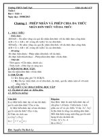
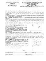
Figure 1 shows the main sections of a general CATV/MATV/SMATV system, indicating the
parts of the IEC 60728-1 series where the relevant performance requirements are indicated.
Copyrighted material licensed to BR Demo by Thomson Reuters (Scientific), Inc., subscriptions.techstreet.com, downloaded on Nov-27-2014 by James Madison. No further reproduction or distribution is permitted. Uncontrolled when printe
–6–
–7–
•
The requirements for the signals received at the headend are given in Clause 6 of
IEC 60728-1:2014.
•
The requirements for the CATV/MATV/SMATV cable network, assuming an unimpaired
input signal at the input of the headend, up to the system outlet are given in
IEC 60728-1:2014, Clause 5.
•
The requirements for the CATV/MATV/SMATV cable network up to the home network
interface (HNI) are given in IEC 60728-1:2014, Clause 7, assuming an unimpaired input
signal at the input of the headend.
•
The specific requirements from HNI to the system outlet or terminal input are given in
IEC 60728-1-1:2014, Clause 5, assuming an unimpaired input signal at the HNI.
•
The requirements at the system outlet in operation are given in Clause 7 of this standard.
The expression in operation means that the received signals, with their impairments, are
applied to the headend input of the CATV/MATV/SMATV cable network. The requirements at
the system outlet in operation are derived, therefore, by summing the impairments of the
various cascaded parts of the system and of the input signal.
When a change of signal format from analogue to analogue (e.g. from FM to AM-VSB) or from
digital to digital (e.g. from QPSK to QAM) or from digital to analogue (e.g. from DVB-S/S2 to
AM-VSB or DVB-T to AM-VSB) is made at the headend, the summation of the impairments
that produce a relaxation of requirements at system outlet does not apply . Such a case will be
the equivalence of unimpaired signals applied at the headend input. Therefore, the
requirements at system outlet given in IEC 60728-1:2014 apply.
Performance requirements,
see Clause 7 (in operation)
Antenna system
(or other feeding network)
Terrestrial
antenna
Satellite
antenna
CATV/MATV/SMATV
Headend
Headend
input
Performance
requirements, see
Clause 6 of IEC
60728-1:2014
HNI
Distribution
network
Performance requirements, see
Clause 7 of IEC 60728-1:2014
(unimpaired input signals)
System
oulet
Home network
(HN)
Terminal
equipment
Performance requirements, see
Clause 5 of IEC 60728-1-1:2014
(unimpaired input signals)
Performance requirements, see
Clause 5 of IEC 60728-1:2014
(unimpaired input signals)
IEC 0732/14
Diagram of the main sections of a CATV/MATV/SMATV cable network and the relevant parts
of the IEC 60728-1 series where the requirements are indicated.
Figure 1 – CATV/MATV/SMATV cable network – Performance requirements
This standard also provides references for the basic methods of measurement of the
operational characteristics of the downstream cable network in order to assess its
performance.
All requirements refer to the performance limits to be achieved in operation at any system
outlet when terminated in a resistance equal to the nominal load impedance of the system,
Copyrighted material licensed to BR Demo by Thomson Reuters (Scientific), Inc., subscriptions.techstreet.com, downloaded on Nov-27-2014 by James Madison. No further reproduction or distribution is permitted. Uncontrolled when printe
IEC 60728-1-2:2014 © IEC 2014
IEC 60728-1-2:2014 © IEC 2014
unless otherwise specified. Where system outlets are not used, the above applies to the
terminal input.
If the home network is subdivided into a number of parts, using different transmission media
(e.g. coaxial cabling, balanced cabling, optical cabling, wireless links) the accumulation of
degradations should not exceed the figures given below.
NOTE Performance requirements of return paths as well as special methods of measurement for the use of the
return paths in cable networks are described in IEC 60728-10.
Copyrighted material licensed to BR Demo by Thomson Reuters (Scientific), Inc., subscriptions.techstreet.com, downloaded on Nov-27-2014 by James Madison. No further reproduction or distribution is permitted. Uncontrolled when printe
–8–
–9–
CABLE NETWORKS FOR TELEVISION SIGNALS,
SOUND SIGNALS AND INTERACTIVE SERVICES –
Part 1-2: Performance requirements for signals
delivered at the system outlet in operation
1
Scope
This part of IEC 60728 provides the minimum performance requirements to be fulfilled in
operation at the system outlet or terminal input and describes the summation criteria for the
impairments present in the received signals and those produced by the CATV/MATV/SMATV
cable network, including individual receiving systems.
In a building divided into apartment blocks, the signals received by the antennas are
distributed by the MATV/SMATV cable network up to the home network interface (HNI). The
television signals are then distributed (inside the home) by home networks (HN) of various
types up to the system outlet or terminal input. The cable network can support two way
operation, from the system outlet (or terminal input) towards the headend.
The home network can use coaxial cables, balanced pair cables, fibre optic cables (glass or
plastic) and also wireless links inside a room (or a small number of adjacent rooms) to replace
wired cords.
This part of IEC 60728 is applicable to cable networks intended for television signals, sound
signals and interactive services operating between about 5 MHz and 3 000 MHz. The
frequency range is extended to 6 000 MHz for home distribution techniques that replace wired
cords with a wireless two way communication inside a room (or a small number of adjacent
rooms) that uses the 5 GHz to 6 GHz frequency band.
2
Normative references
The following documents, in whole or in part, are normatively referenced in this document and
are indispensable for its application. For dated references, only the edition cited applies. For
undated references, the latest edition of the referenced document (including any
amendments) applies.
IEC 60050-705, International Electrotechnical Vocabulary – Chapter 705: Radio wave
propagation
IEC 60050-712, International Electrotechnical Vocabulary – Chapter 712: Antennas
IEC 60050-725, International
radiocommunications
Electrotechnical
Vocabulary
–
Chapter
725:
Space
IEC 60728-1:2014, Cable networks for television signals, sound signals and interactive
services – Part 1: System performance of forward paths
IEC 60728-1-1:2014, Cable networks for television signals, sound signals and interactive
services – Part 1-1: RF cabling for two way home networks
IEC 60728-3:2010, Cable networks for television signals sound signals and interactive
services – Part 3: Active wideband equipment for cable networks
Copyrighted material licensed to BR Demo by Thomson Reuters (Scientific), Inc., subscriptions.techstreet.com, downloaded on Nov-27-2014 by James Madison. No further reproduction or distribution is permitted. Uncontrolled when printe
IEC 60728-1-2:2014 © IEC 2014
IEC 60728-1-2:2014 © IEC 2014
IEC 60966-2-4, Radio frequency and coaxial cable assemblies – Part 2-4: Detail specification
for cable assemblies for radio and TV receivers – Frequency range 0 MHz to 3 000 MHz,
IEC 61169-2 connectors
IEC 60966-2-5, Radio frequency and coaxial cable assemblies – Part 2-5: Detail specification
for cable assemblies for radio and TV receivers – Frequency range 0 MHz to 1 000 MHz,
IEC 61169-2 connectors
IEC 60966-2-6, Radio frequency and coaxial cable assemblies – Part 2-6: Detail specification
for cable assemblies for radio and TV receivers – Frequency range 0 MHz to 3 000 MHz,
IEC 61169-24 connectors
ITU-R Recommendation BT.500, Methodology for the subjective assessment of the quality of
television pictures
ITU-R Recommendation BT.654, Subjective quality of television pictures in relation to the
main impairments of the analogue composite television signal
ITU-R Recommendation BT.655, Radio-frequency protection ratios for AM vestigial sideband
terrestrial television systems interfered with by unwanted analogue vision signals and their
associated sound signals
ITU-T Recommendation J.61, Transmission performance of television circuits designed for
use in international connections
ITU-T Recommendation J.63, Insertion of test signals in the field-blanking interval of
monochrome and colour television signals
ETSI EN 300 421, Digital Video Broadcasting (DVB); Framing structure, channel coding and
modulation for 11/12 GHz satellite services
ETSI EN 300 429, Digital Video Broadcasting (DVB); Framing structure, channel coding and
modulation for cable systems
ETSI EN 300 473, Digital Video Broadcasting (DVB); Satellite Master Antenna Television
(SMATV) distribution systems
ETSI EN 300 744, Digital Video Broadcasting (DVB); Framing structure, channel coding and
modulation for digital terrestrial television
ETSI EN 302 307, Digital Video Broadcasting (DVB); Second generation framing structure,
channel coding and modulation systems for Broadcasting, Interactive Services, News
Gathering and other broadband satellite applications
ETSI EN 302 755, Digital Video Broadcasting (DVB) – Frame structure, channel coding and
modulation for a second generation digital terrestrial television broadcasting system (DVB-T2)
3
Terms, definitions, symbols and abbreviations
3.1
Terms and definitions
For the purposes of this document, the terms and definitions given in IEC 60050-705,
IEC 60050-712, IEC 60050-725 and IEC 60728-1, as well as the following, apply.
NOTE
The most important definitions are repeated below.
Copyrighted material licensed to BR Demo by Thomson Reuters (Scientific), Inc., subscriptions.techstreet.com, downloaded on Nov-27-2014 by James Madison. No further reproduction or distribution is permitted. Uncontrolled when printe
– 10 –
– 11 –
3.1.1
active home network
home network that uses active equipment (for example, amplifiers) in addition to passive
equipment such as splitters, taps, system outlets, cables and connectors up to the coaxial RF
interface (input and/or output) of the terminal equipment for distributing and combining RF
signals
3.1.2
antenna
part of a radio transmitting or receiving system which is designed to provide the required
coupling between a transmitter or a receiver and the medium in which the radio wave
propagates
Note 1 to entry: In practice, the terminals of the antenna or the points to be considered as the interface between
the antenna and the transmitter or receiver should be specified.
Note 2 to entry: If the transmitter or receiver is connected to its antenna by a feeder line, the antenna may be
considered to be a transducer between the guided radio waves of the feeder line and the radiated waves in space.
[SOURCE: IEC 60050-712:1992,
line has been used.]
712-01-01, modified – The term feeder line instead of feed
3.1.3
attenuation
ratio of the input power to the output power of an equipment or system
Note 1 to entry:
The ratio is expressed in decibels.
3.1.4
balun
device for transforming an unbalanced voltage to a balanced voltage or vice-versa
Note 1 to entry:
The term is derived from "balanced to unbalanced transformer".
3.1.5
bit error ratio
BER
ratio between erroneous bits and the total number of transmitted bits
3.1.6
carrier-to-intermodulation ratio
C/I
difference between the carrier level at a specified point in a piece of equipment or a system
and the level of a specified intermodulation product or combination of products
Note 1 to entry:
The difference is expressed in decibels.
3.1.7
carrier-to-noise ratio
C/N
difference between the vision or sound carrier level at a given point in a piece of equipment or
a system and the noise level at that point (measured within a bandwidth appropriate to the
television or radio system in use)
Note 1 to entry:
The difference is expressed in decibels.
3.1.8
CATV network
regional and local broadband cable networks designed to provide sound and television signals
as well as signals for interactive services to a regional or local area
Note 1 to entry:
Originally defined as community antenna television network.
Copyrighted material licensed to BR Demo by Thomson Reuters (Scientific), Inc., subscriptions.techstreet.com, downloaded on Nov-27-2014 by James Madison. No further reproduction or distribution is permitted. Uncontrolled when printe
IEC 60728-1-2:2014 © IEC 2014
IEC 60728-1-2:2014 © IEC 2014
3.1.9
cross-modulation
undesired modulation of the carrier of a desired signal by the modulation of another signal as
a result of equipment or system non-linearities
3.1.10
decibel ratio
ten times the logarithm to base 10 of the ratio of two quantities of power P 1 and P 2 , that is
P
10 lg 1
P2
Note 1 to entry:
Quantities of power may also be expressed in terms of voltages.
20 lg
Note 2 to entry:
in dB
U1
U2
in dB
The abbreviation “lg” in equations signifies “log 10 ”.
3.1.11
directivity
attenuation between output port and interface or tap port minus the attenuation between input
port and interface or tap port, of any equipment or system
3.1.12
distribution amplifier
amplifier designed to feed one or more branch or spur feeders
Note 1 to entry:
This is a general term embracing branch amplifier and spur amplifier.
3.1.13
DOCSIS
EuroDOCSIS
standards defining interface specifications for cable modems and cable modem termination
systems for high-speed data communication over RF cable networks
3.1.14
dwelling unit
DU
home or office where television and sound signals are distributed and where there is access
to interactive services
3.1.15
echo rating
E
result of a system test with a 2T sine-squared pulse using the boundary line on a specified
graticule within which all parts of the received pulse fall
SEE: Figure Figure 24 of IEC 60728-1:2014.
Note 1 to entry:
Determined in ITU-T Recommendation J.61 and ITU-T Recommendation J.63
Note 2 to entry: The object of the graticule design is to ensure that the subjective effect of an echo of rating E %
is the same as that of a single echo, with displacement greater than 12T, of (E/2) % relative to the peak amplitude
of the test pulse.
3.1.16
extended satellite television distribution network
extended satellite television distribution system
distribution network or system designed to provide sound and television signals received by
satellite receiving antenna to households in one or more buildings
Copyrighted material licensed to BR Demo by Thomson Reuters (Scientific), Inc., subscriptions.techstreet.com, downloaded on Nov-27-2014 by James Madison. No further reproduction or distribution is permitted. Uncontrolled when printe
– 12 –
– 13 –
Note 1 to entry: This kind of network or system can be combined with terrestrial antennas for the additional
reception of TV and/or radio signals via terrestrial networks.
Note 2 to entry: This kind of network or system can also carry control signals for satellite switched systems or
other signals for special transmission systems (e.g. MoCA or WiFi) in the return path direction.
3.1.17
extended terrestrial television distribution network
extended terrestrial television distribution system
distribution network or system designed to provide sound and television signals received by
terrestrial receiving antenna to households in one or more buildings
Note 1 to entry: This kind of network or system can be combined with a satellite antenna for the additional
reception of TV and/or radio signals via satellite networks.
Note 2 to entry: This kind of network or system can also carry other signals for special transmission systems (e.g.
MoCA or WiFi) in the return path direction.
3.1.18
feeder
transmission path forming part of a cable network
Note 1 to entry:
Such a path may consist of a metallic cable, optical fibre, waveguide, or any combination of them.
Note 2 to entry:
By extension, the term is also applied to paths containing one or more radio links.
3.1.19
gain
ratio of the output power to the input power of any equipment or system
Note 1 to entry:
The ratio is expressed in decibels.
3.1.20
headend
equipment which is connected between receiving antennas or other signal sources and the
remainder of the cable networks, to process the signals to be distributed
Note 1 to entry: The headend may, for example, comprise antenna amplifiers, frequency converters, combiners,
separators and generators.
3.1.21
headend input
interface of the headend where the signals received by antennas or individual feeder lines are
applied for signal processing
3.1.22
home network
HN
RF cable network inside a single dwelling (one-family house or one unit of a multi-dwelling
building) in the SOHO (Small Offices Home Offices) environments or in the rooms of hotels,
hospitals
Note 1 to entry:
The preferred topology of this network is a star.
Note 2 to entry: This network carries television signals, sound signals and interactive services up to the coaxial
RF interface (input and/or output) of the terminal equipment. It may comprise active equipment, passive equipment,
cables and connectors.
3.1.23
home network interface
HNI
interface for access to the network for transmission of television signals, sound signals and
interactive services inside a home (single dwelling)
Copyrighted material licensed to BR Demo by Thomson Reuters (Scientific), Inc., subscriptions.techstreet.com, downloaded on Nov-27-2014 by James Madison. No further reproduction or distribution is permitted. Uncontrolled when printe
IEC 60728-1-2:2014 © IEC 2014
IEC 60728-1-2:2014 © IEC 2014
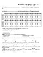
Note 1 to entry: It is the first accessible point after the entrance of the network into an individual home (see
Figure 2)
Note 2 to entry: In some cases the home network interface may coincide with the system outlet. In this case the
performance requirements for a system outlet apply.
Active home network
HNI
Passive home network
HNI
Looped system
outlets
HNI
Single
system
outlet
BNI
IEC 0733/14
Figure 2 – Examples of location of HNI for various home network types
3.1.24
individual satellite television receiving system
system designed to provide sound and television signals received from satellite(s) to an
individual household
Note 1 to entry: This kind of system can also carry control signals for satellite switched systems or other signals
for special transmission systems (e.g. MoCA or WiFi) in the return path direction.
3.1.25
individual terrestrial television receiving system
system designed to provide sound and television signals received via terrestrial broadcast
networks to an individual household
Note 1 to entry: This kind of system can also carry other signals for special transmission systems (e.g. MoCA or
WiFi) in the return path direction.
3.1.26
intermodulation
process whereby non-linearity of equipment in a system produces output signals (called
intermodulation products) at frequencies which are linear combinations of those of the input
signals
Copyrighted material licensed to BR Demo by Thomson Reuters (Scientific), Inc., subscriptions.techstreet.com, downloaded on Nov-27-2014 by James Madison. No further reproduction or distribution is permitted. Uncontrolled when printe
– 14 –
– 15 –
3.1.27
isolation
attenuation between two output, tap or interface ports of any equipment or system
3.1.28
3.1.28.1
level
decibel ratio of any power P 1 to the standard reference power P 0 , that is
10 lg
Note 1 to entry:
P1
P0
in dB
The ratio is given in decibel (dB).
Note 2 to entry: This may be expressed in decibels (relative to 1 µV in 75 Ω) or more simply in dB(µV) if there is
no risk of ambiguity.
3.1.28.2
level
decibel ratio of any voltage U 1 to the standard reference voltage U 0 , that is
20 lg
Note 1 to entry:
U1
U0
in dB
The ratio is given in decibel (dB).
Note 2 to entry: This may be expressed in decibels (relative to 1 µV in 75 Ω) or more simply in dB(µV) if there is
no risk of ambiguity.
3.1.29
local broadband cable network
network designed to provide sound and television signals as well as signals for interactive
services to a local area (e.g. one town or one village)
3.1.30
MATV network
extended terrestrial television distribution networks or systems designed to provide sound and
television signals received by terrestrial receiving antenna to households in one or more
buildings
Note 1 to entry:
Originally defined as Master Antenna Television network.
Note 2 to entry: This kind of network or system can be combined with a satellite antenna for the additional
reception of TV and/or radio signals via satellite networks.
Note 3 to entry: This kind of network or system can also carry other signals for special transmission systems (e.g.
MoCA or WiFi) in the return path direction.
3.1.31
multiplex
signals from several separate sources assembled into a single composite signal for
transmission over a common transmission channel
[SOURCE: IEC 60050-701:1988, 701-03-09, modified – Term and definition have been
changed to describe the result of the multiplexing process.]
3.1.32
mutual isolation
attenuation between two specified system outlets at any frequency within the range of the
system under investigation which is always specified, for any particular installation, as the
minimum value obtained within specified frequency limits
Copyrighted material licensed to BR Demo by Thomson Reuters (Scientific), Inc., subscriptions.techstreet.com, downloaded on Nov-27-2014 by James Madison. No further reproduction or distribution is permitted. Uncontrolled when printe
IEC 60728-1-2:2014 © IEC 2014
IEC 60728-1-2:2014 © IEC 2014
3.1.33
network interface
NI
interface to the network for transmission of television signals, sound signals and interactive
services
3.1.34
receiver lead
lead which connects the system outlet to the subscriber’s equipment
Note 1 to entry:
A receiver lead may include filters and balun transformers in addition to the cable.
3.1.35
regional broadband cable network
network designed to provide sound and television signals as well as signals for interactive
services to a regional area covering several towns and/or villages
3.1.36
SMATV headend
headend in block of flats or in built-up sites to feed TV channels received by satellite into the
house network or the spur network
Note 1 to entry:
In some cases, a distribution point may be connected directly to the headend.
3.1.37
SMATV network
extended distribution networks or systems designed to provide sound and television signals
received by satellite receiving antenna to households in one or more buildings
Note 1 to entry:
Originally defined as satellite master antenna television network.
Note 2 to entry: This kind of network or system can be combined with terrestrial antennas for the additional
reception of TV and/or radio signals via terrestrial networks.
Note 3 to entry: This kind of network or system can also carry control signals for satellite switched systems or
other signals for special transmission systems (e.g. MoCA or WiFi) in the return path direction.
3.1.38
satellite master antenna system
SMATV
system which is designed to provide sound and television signals to the outlets of a building
or a group of buildings
Note 1 to entry:
Two system configurations are defined in ETSI EN 300 473 as follows:
•
SMATV system A, based on transparent transmodulation of QPSK satellite signals into QAM signals to be
distributed to the user;
•
SMATV system B, based on direct distribution of QPSK signals to the user, with two options:
–
SMATV-IF distribution in the satellite IF band (above 950 MHz);
–
SMATV-S distribution in the VHF/UHF band, for example in the extended S band (230 MHz to 470 MHz)
3.1.39
S D,RF /N
signal-to-noise ratio for a digitally modulated signal in the RF band
3.1.40
single dwelling unit
SDU
home or office used by a single owner where television and sound signals are distributed and
with access to interactive services
Copyrighted material licensed to BR Demo by Thomson Reuters (Scientific), Inc., subscriptions.techstreet.com, downloaded on Nov-27-2014 by James Madison. No further reproduction or distribution is permitted. Uncontrolled when printe
– 16 –
– 17 –
3.1.41
splitter
spur unit
device in which the signal power at the (input) port is divided equally or unequally between
two or more (output) ports
Note 1 to entry:
Some forms of this device may be used in the reverse direction for combining signal energy.
3.1.42
spur feeder
feeder to which splitters, subscriber taps, or looped system outlets are connected
3.1.43
standard reference power
P0
<in cable networks> 1/75 pW
Note 1 to entry:
This is the power dissipated in a 75 Ω resistor with a voltage drop of 1 µV RMS across it.
3.1.44
subscriber feeder
feeder connecting a subscriber tap to a system outlet or, where the latter is not used, directly
to the subscriber equipment
Note 1 to entry:
A subscriber feeder may include filters and balun transformers.
3.1.45
subscriber equipment
equipment at the subscriber premises such as receivers, tuners, decoders, video recorders
3.1.46
subscriber tap
device for connecting a subscriber feeder to a spur feeder
3.1.47
system outlet
SO
device for interconnecting a subscriber feeder and a receiver lead
3.1.48
terminal equipment
equipment (television receiver, radio receiver, set-top box, etc.) able to receive the distributed
signals or to send (via a cable modem) return signals for interactive services
3.1.49
well-matched
matching condition when the return loss of the equipment complies with the requirements of
Table 1 of IEC 60728-3:2010
3.2
Abbreviations
APSK
amplitude and phase shift keying
AWGN
additive white Gaussian noise
BBUW
base-band un-weighted noise
BBWN
base-band weighted noise
BER
bit error ratio
BW
bandwidth
C/N
carrier-to-noise ratio (ratio of RF
or IF power to noise power)
CATV
community antenna television
Copyrighted material licensed to BR Demo by Thomson Reuters (Scientific), Inc., subscriptions.techstreet.com, downloaded on Nov-27-2014 by James Madison. No further reproduction or distribution is permitted. Uncontrolled when printe
IEC 60728-1-2:2014 © IEC 2014
IEC 60728-1-2:2014 © IEC 2014
COFDM
coded orthogonal frequency
division multiplex
DA
distribution amplifier
DAB
digital audio broadcasting
DOCSIS
Data Over Cable Service
Interface Specification
DVB
digital video broadcasting
DVB-C
digital video broadcasting
baseline system for digital cable
television
(ETSI EN 300 429)
DVB-CS
digital video broadcasting
baseline system for SMATV
distribution systems
(ETSI EN 300 473)
DVB-S
digital video broadcasting
baseline system for digital
satellite television
(ETSI EN 300 421)
DVB-S2
digital video broadcasting
baseline system for digital
satellite television second
generation (ETSI EN 302 307)
DVB-T
digital video broadcasting
baseline system for digital
terrestrial television
(ETSI EN 300 744)
DVB-T2
digital video broadcasting
baseline system for digital
terrestrial television second
generation (ETSI EN 302 755)
Euro
DOCSIS
European Data Over Cable
Service Interface Specification
FDM
frequency division multiplex
FM
frequency modulation
HFC
Hybrid Fibre Coaxial
HN
home network
HNI
home network interface
ITS
insertion test signal
LDPC
low-density parity check (codes)
LNB
low noise block converter
(frequency converter in the focal
point of a parabolic antenna)
MATV
master antenna television
MoCA
multimedia over cable alliance
NB
noise bandwidth
NICAM
near-instantaneously companded
audio multiplex
NTSC
national television system
committee
OFDM
orthogonal frequency division
multiplex
PAL
phase alternation line
PSK
phase shift keying
QAM
quadrature amplitude modulation
QEF
quasi-error-free
QPSK
quaternary phase shift keying
RF
radio frequency
RMS
root mean square
SDU
single dwelling unit
SECAM
séquenciel couleur à mémoire
SMATV
satellite master antenna
television
SO
system outlet
SOHO
small office, home office
TI
terminal input
TS
transport stream
TV
television
UHF
ultra-high frequency
VHF
very high frequency
VSB
vestigial side band
WiFi
Wireless Fidelity
4
Methods of measurement
The methods of measurement applicable in operation are concerned mainly with the most
important characteristics and requirements that shall be fulfilled at system outlet (SO) or
terminal input (TI) in operation.
Copyrighted material licensed to BR Demo by Thomson Reuters (Scientific), Inc., subscriptions.techstreet.com, downloaded on Nov-27-2014 by James Madison. No further reproduction or distribution is permitted. Uncontrolled when printe
– 18 –