Iec 60728 1 2014
Bạn đang xem bản rút gọn của tài liệu. Xem và tải ngay bản đầy đủ của tài liệu tại đây (1.45 MB, 158 trang )
IEC 60728-1:2014-05(en)
®
Edition 5.0 2014-05
INTERNATIONAL
STANDARD
Cable networks for television signals, sound signals and interactive services –
Part 1: System performance of forward paths
Copyrighted material licensed to BR Demo by Thomson Reuters (Scientific), Inc., subscriptions.techstreet.com, downloaded on Nov-27-2014 by James Madison. No further reproduction or distribution is permitted. Uncontrolled when printe
IEC 60728-1
Copyright © 2014 IEC, Geneva, Switzerland
All rights reserved. Unless otherwise specified, no part of this publication may be reproduced or utilized in any form
or by any means, electronic or mechanical, including photocopying and microfilm, without permission in writing from
either IEC or IEC's member National Committee in the country of the requester. If you have any questions about IEC
copyright or have an enquiry about obtaining additional rights to this publication, please contact the address below or
your local IEC member National Committee for further information.
IEC Central Office
3, rue de Varembé
CH-1211 Geneva 20
Switzerland
Tel.: +41 22 919 02 11
Fax: +41 22 919 03 00
www.iec.ch
About the IEC
The International Electrotechnical Commission (IEC) is the leading global organization that prepares and publishes
International Standards for all electrical, electronic and related technologies.
About IEC publications
The technical content of IEC publications is kept under constant review by the IEC. Please make sure that you have the
latest edition, a corrigenda or an amendment might have been published.
IEC Catalogue - webstore.iec.ch/catalogue
The stand-alone application for consulting the entire
bibliographical information on IEC International Standards,
Technical Specifications, Technical Reports and other
documents. Available for PC, Mac OS, Android Tablets and
iPad.
Electropedia - www.electropedia.org
The world's leading online dictionary of electronic and
electrical terms containing more than 30 000 terms and
definitions in English and French, with equivalent terms in 14
additional languages. Also known as the International
Electrotechnical Vocabulary (IEV) online.
IEC publications search - www.iec.ch/searchpub
The advanced search enables to find IEC publications by a
variety of criteria (reference number, text, technical
committee,…). It also gives information on projects, replaced
and withdrawn publications.
IEC Glossary - std.iec.ch/glossary
More than 55 000 electrotechnical terminology entries in
English and French extracted from the Terms and Definitions
clause of IEC publications issued since 2002. Some entries
have been collected from earlier publications of IEC TC 37,
77, 86 and CISPR.
IEC Just Published - webstore.iec.ch/justpublished
Stay up to date on all new IEC publications. Just Published
details all new publications released. Available online and
also once a month by email.
IEC Customer Service Centre - webstore.iec.ch/csc
If you wish to give us your feedback on this publication or
need further assistance, please contact the Customer Service
Centre:
Copyrighted material licensed to BR Demo by Thomson Reuters (Scientific), Inc., subscriptions.techstreet.com, downloaded on Nov-27-2014 by James Madison. No further reproduction or distribution is permitted. Uncontrolled when printe
THIS PUBLICATION IS COPYRIGHT PROTECTED
®
Edition 5.0 2014-05
INTERNATIONAL
STANDARD
Cable networks for television signals, sound signals and interactive services –
Part 1: System performance of forward paths
INTERNATIONAL
ELECTROTECHNICAL
COMMISSION
ICS 33.060.40
PRICE CODE
ISBN 978-2-8322-1619-4
Warning! Make sure that you obtained this publication from an authorized distributor.
® Registered trademark of the International Electrotechnical Commission
XG
Copyrighted material licensed to BR Demo by Thomson Reuters (Scientific), Inc., subscriptions.techstreet.com, downloaded on Nov-27-2014 by James Madison. No further reproduction or distribution is permitted. Uncontrolled when printe
IEC 60728-1
IEC 60728-1:2014 © IEC 2014
CONTENTS
FOREWORD ......................................................................................................................... 10
INTRODUCTION ................................................................................................................... 12
1
Scope ............................................................................................................................ 13
2
Normative references .................................................................................................... 13
3
Terms, definitions, symbols and abbreviations ............................................................... 15
4
3.1
Terms and definitions ....................................................................................... 15
3.2
Symbols ........................................................................................................... 27
3.3
Abbreviations ................................................................................................... 29
Methods of measurement at system outlet ..................................................................... 31
4.1
4.2
4.3
4.4
4.5
4.6
4.7
Performance limits ........................................................................................... 31
Mutual isolation between system outlets .......................................................... 33
4.2.1
Overview ........................................................................................ 33
4.2.2
Equipment required ........................................................................ 33
4.2.3
Connection of the equipment .......................................................... 34
4.2.4
Measurement procedure ................................................................. 34
4.2.5
Presentation of the results .............................................................. 35
Amplitude response within a channel ............................................................... 35
4.3.1
Overview ........................................................................................ 35
4.3.2
Equipment required ........................................................................ 35
4.3.3
Connection of the equipment .......................................................... 35
4.3.4
Measurement procedure ................................................................. 36
4.3.5
Presentation of the results .............................................................. 37
Chrominance-luminance gain and delay inequalities ........................................ 38
4.4.1
Overview ........................................................................................ 38
4.4.2
Equipment required ........................................................................ 39
4.4.3
Connection of the equipment .......................................................... 39
4.4.4
Measurement procedure ................................................................. 39
4.4.5
Presentation of the results .............................................................. 40
Non-linear distortion......................................................................................... 41
4.5.1
General .......................................................................................... 41
4.5.2
Intermodulation ............................................................................... 41
4.5.3
Composite beat .............................................................................. 41
4.5.4
Composite crossmodulation ............................................................ 45
4.5.5
Intermodulation noise ..................................................................... 46
4.5.6
Hum modulation of carriers ............................................................. 46
4.5.7
Differential gain and phase ............................................................. 51
Carrier-to-noise ratio ........................................................................................ 56
4.6.1
Overview ........................................................................................ 56
4.6.2
Equipment required ........................................................................ 56
4.6.3
Connection of the equipment .......................................................... 56
4.6.4
Measurement set-up ....................................................................... 57
4.6.5
Measurement procedure ................................................................. 57
4.6.6
Presentation of the results .............................................................. 58
Echoes ............................................................................................................ 58
4.7.1
Overview ........................................................................................ 58
4.7.2
Equipment required ........................................................................ 59
Copyrighted material licensed to BR Demo by Thomson Reuters (Scientific), Inc., subscriptions.techstreet.com, downloaded on Nov-27-2014 by James Madison. No further reproduction or distribution is permitted. Uncontrolled when printe
–2–
5
–3–
4.7.3
Connection of the equipment .......................................................... 59
4.7.4
Measurement procedure ................................................................. 59
4.7.5
Presentation of the results .............................................................. 60
AM-VSB television, FM radio and FM television signal level ............................. 60
4.8
4.8.1
General .......................................................................................... 60
4.8.2
Definitions for NTSC, PAL and SECAM systems ............................. 60
4.8.3
Equipment required ........................................................................ 60
4.8.4
Measurement procedure ................................................................. 60
4.8.5
Presentation of the results .............................................................. 61
Data echo rating and data delay inequality ....................................................... 61
4.9
4.10
Interference in FM sound radio channels .......................................................... 61
4.11
Methods of measurement for digitally modulated signals .................................. 61
4.11.1
Overview ........................................................................................ 61
4.11.2
Basic assumptions and measurement interfaces ............................. 62
4.11.3
Signal level for digitally modulated signals ...................................... 65
4.11.4
RF signal-to-noise ratio S D,RF /N for digitally modulated
signals ............................................................................................ 66
4.11.5
Bit error ratio (BER) ........................................................................ 68
4.11.6
BER versus E b /N 0 or C/N ............................................................... 69
4.11.7
Noise margin .................................................................................. 73
4.11.8
Modulation error ratio (MER) .......................................................... 74
4.11.9
Phase jitter ..................................................................................... 76
4.11.10
Phase noise of an RF carrier .......................................................... 79
Performance requirements at system outlet ................................................................... 82
5.1
5.2
5.3
5.4
5.5
5.6
5.7
5.8
5.9
General ............................................................................................................ 82
Impedance ....................................................................................................... 82
Requirements at the terminal input ................................................................... 82
5.3.1
General .......................................................................................... 82
5.3.2
Signal level ..................................................................................... 83
5.3.3
Other parameters ........................................................................... 83
Carrier levels at system outlets ........................................................................ 83
5.4.1
Minimum and maximum carrier levels ............................................. 83
5.4.2
Carrier level differences .................................................................. 85
Mutual isolation between system outlets .......................................................... 86
5.5.1
Isolation between two subscribers .................................................. 86
5.5.2
Isolation between individual outlets in one household ..................... 86
5.5.3
Isolation between forward and return path ...................................... 86
Frequency response within a television channel at any system outlet ............... 87
5.6.1
Amplitude response ........................................................................ 87
5.6.2
Group delay .................................................................................... 87
Long-term frequency stability of distributed carrier signals at any system
outlet ............................................................................................................... 88
Random noise .................................................................................................. 89
Interference to television channels ................................................................... 91
5.9.1
Single-frequency interference ......................................................... 91
5.9.2
Single-channel intermodulation interference ................................... 92
5.9.3
Multiple frequency intermodulation interference .............................. 92
5.9.4
Intermodulation noise ..................................................................... 92
5.9.5
Cross-modulation ........................................................................... 93
Copyrighted material licensed to BR Demo by Thomson Reuters (Scientific), Inc., subscriptions.techstreet.com, downloaded on Nov-27-2014 by James Madison. No further reproduction or distribution is permitted. Uncontrolled when printe
IEC 60728-1:2014 © IEC 2014
IEC 60728-1:2014 © IEC 2014
5.10
6
Video baseband requirements .......................................................................... 93
5.10.1
Differential gain and phase in any television channel ...................... 93
5.10.2
Echoes ........................................................................................... 93
Hum modulation of carriers in television channels ............................................ 93
5.11
5.12
Requirements for data signal transmission ....................................................... 94
5.12.1
Data signals carried in the structure of a television signal ............... 94
5.12.2
Data signals other than those carried within the structure of a
television signal .............................................................................. 94
5.13
Digitally modulated signals – Additional performance requirements ................. 94
5.13.1
DVB (PSK, QAM, OFDM) performance ........................................... 94
5.13.2
NICAM performance ....................................................................... 96
5.13.3
DAB performance ........................................................................... 96
FM sound radio – Additional performance requirements ................................... 97
5.14
5.14.1
Amplitude response within an FM channel ...................................... 97
5.14.2
Phase response within an FM channel ............................................ 97
5.14.3
Interference within an FM channel .................................................. 97
5.14.4
AM hum modulation on FM sound carriers ...................................... 97
5.14.5
Echoes within an FM channel ......................................................... 97
Performance requirements at receiving antennas .......................................................... 97
6.1
6.2
7
General ............................................................................................................ 97
Method of measurement of field strength ......................................................... 98
6.2.1
Overview ........................................................................................ 98
6.2.2
Equipment required ........................................................................ 98
6.2.3
Connection of the equipment .......................................................... 98
6.2.4
Measurement procedure ................................................................. 98
6.2.5
Presentation of the results ............................................................ 100
Requirements ................................................................................................ 100
6.3
6.3.1
General ........................................................................................ 100
6.3.2
Field strength requirements .......................................................... 100
6.3.3
Quality of received signals ............................................................ 102
6.3.4
Safety ........................................................................................... 106
6.3.5
Electromagnetic compatibility (EMC) ............................................ 107
Interference reduction .................................................................................... 107
6.4
6.4.1
General ........................................................................................ 107
6.4.2
Active antennas ............................................................................ 107
Performance requirements at home network interfaces of cable networks.................... 107
7.1
7.2
7.3
General .......................................................................................................... 107
Requirements at HNI1 for passive coaxial home networks ............................. 108
7.2.1
General ........................................................................................ 108
7.2.2
Carrier levels at the HNI1 ............................................................. 109
7.2.3
Mutual isolation between two HNI1 ............................................... 112
7.2.4
Frequency response within any television channel at HNI1 ........... 112
7.2.5
Long-term frequency stability of distributed carrier signals at
HNI1 ............................................................................................. 113
7.2.6
Random noise at the HNI1 ............................................................ 113
7.2.7
Interference to television channels at HNI1 ................................... 113
7.2.8
Return path requirements at HNI1 ................................................ 114
Requirements at HNI2 for active coaxial home networks ................................ 114
7.3.1
General ........................................................................................ 114
Copyrighted material licensed to BR Demo by Thomson Reuters (Scientific), Inc., subscriptions.techstreet.com, downloaded on Nov-27-2014 by James Madison. No further reproduction or distribution is permitted. Uncontrolled when printe
–4–
–5–
7.3.2
7.3.3
7.3.4
7.3.5
7.4
7.5
7.6
Annex A
Carrier levels at the HNI2 ............................................................. 114
Mutual isolation between two HNI2 ............................................... 117
Frequency response within any television channel at HNI2 ........... 117
Long-term frequency stability of distributed carrier signals at
HNI2 ............................................................................................. 117
7.3.6
Random noise at HNI2 .................................................................. 118
7.3.7
Interference to television channels at the HNI2 ............................. 121
7.3.8
Return path requirements at HNI2 ................................................ 122
Requirements at HNI3 and at system outlet or terminal input when the
home network is mainly of balanced type ....................................................... 122
7.4.1
Overview ...................................................................................... 122
7.4.2
Requirements at HNI3 .................................................................. 122
7.4.3
Requirements at system output ..................................................... 123
7.4.4
Additional requirements at HNI3 for upstream transmission .......... 123
Requirements at HNI3 (Case C) ..................................................................... 124
Requirements at HNI3 (Case D) ..................................................................... 124
(informative) Reception of television signals ........................................................ 125
Annex B (normative) Calibration of modulation depth ......................................................... 130
B.1
Equipment required ........................................................................................ 130
B.2
Connection of the equipment ......................................................................... 130
B.3
Calibration procedure ..................................................................................... 130
Annex C (normative) Equipment required – Additional items .............................................. 131
C.1
Measuring receiver preamplifier ..................................................................... 131
C.2
Measuring receiver input filter ........................................................................ 131
Annex D (normative) Preliminary checks on the measuring equipment for carrier-tonoise ratio ................................................................................................................... 132
D.1
Noise ............................................................................................................. 132
D.2
Intermodulation .............................................................................................. 132
D.3
Overload ........................................................................................................ 132
Annex E (normative) Correction factors.............................................................................. 133
E.1
Level correction factor C m ............................................................................. 133
E.2
Bandwidth correction factor C b ...................................................................... 133
Annex F (normative) Calibration of the measuring receiver ................................................ 134
Annex G (normative) Correction factors for noise ............................................................... 135
G.1
Signal level measurement .............................................................................. 135
G.2
Noise level measurement ............................................................................... 135
Annex H (normative) Null packet and PRBS definitions ...................................................... 137
H.1
Null packet definition...................................................................................... 137
H.2
PRBS definition.............................................................................................. 138
Annex I (normative) Digital signal level and bandwidth ....................................................... 139
I.1
I.2
RF/IF power (carrier) ..................................................................................... 139
Bandwidth of a digital signal .......................................................................... 139
I.2.1
Occupied bandwidth ..................................................................... 139
I.2.2
Noise bandwidth ........................................................................... 140
I.2.3
Equivalent signal bandwidth ......................................................... 140
I.3
Examples ....................................................................................................... 141
Annex J (normative) Correction factor for a spectrum analyser .......................................... 142
Annex K (informative) Differences in some countries ......................................................... 143
Copyrighted material licensed to BR Demo by Thomson Reuters (Scientific), Inc., subscriptions.techstreet.com, downloaded on Nov-27-2014 by James Madison. No further reproduction or distribution is permitted. Uncontrolled when printe
IEC 60728-1:2014 © IEC 2014
IEC 60728-1:2014 © IEC 2014
K.1
K.2
Subclause 3.1.58, Norway ............................................................................. 143
Subclause 5.4.1, Japan, Netherlands ............................................................. 143
K.2.1
Japan ........................................................................................... 143
K.2.2
Netherlands .................................................................................. 143
K.3
Subclause 5.4.2, Japan .................................................................................. 143
K.4
Subclause 5.5.1, Japan .................................................................................. 144
K.5
Subclause 5.6.1, Japan .................................................................................. 145
K.6
Subclause 5.6.2, Netherlands ........................................................................ 145
K.7
Subclause 5.7, Japan..................................................................................... 146
K.8
Subclause 5.8, Japan..................................................................................... 146
K.9
Subclause 5.9.1, Japan, Netherlands ............................................................. 147
K.9.1
Japan ........................................................................................... 147
K.9.2
Netherlands .................................................................................. 148
K.10
Subclause 5.9.5, Japan .................................................................................. 149
K.11
Subclause 5.10.2, Netherlands, Japan ........................................................... 149
K.11.1
Netherlands .................................................................................. 149
K.11.2
Japan ........................................................................................... 149
K.12
Subclause 5.11, Japan ................................................................................... 150
K.13
Subclause 5.12.1, Denmark ........................................................................... 151
K.14
Subclause 5.13.1.5, Japan ............................................................................. 151
K.15
Subclause 5.14.3, Netherlands ...................................................................... 151
K.16
Clause 7, Japan ............................................................................................. 151
Bibliography ........................................................................................................................ 152
Figure 1 – Arrangement of test equipment for measurement of mutual isolation
between system outlets ........................................................................................................ 34
Figure 2 – Arrangement of test equipment for measurement of frequency response
within a channel .................................................................................................................... 36
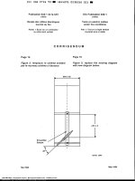
Figure 3 – Interpretation of displays for measurement of frequency response within a
channel ................................................................................................................................. 37
Figure 4 – Test signal (signal F for 625-line systems) employed for
chrominance/luminance gain and delay inequality ................................................................. 38
Figure 5 – Test signal (signal B2 for 625-line systems) employed for
chrominance/luminance gain and delay inequality ................................................................. 38
Figure 6 – Arrangement of test equipment for measurement of chrominance/luminance
gain and delay inequality ...................................................................................................... 39
Figure 7 – Displayed pulses: chrominance low and lagging ................................................... 40
Figure 8 – Displayed pulses: chrominance high and leading ................................................. 40
Figure 9 – Connection of test equipment for the measurement of non-linear distortion
by composite beat ................................................................................................................. 42
Figure 10 – Weighting curve for 625-line system B, G and D1 (PAL): CW interference
with no special (frequency offset) control .............................................................................. 44
Figure 11 – Weighting curve for 625-line system I (PAL): CW interference with no
special (frequency offset) control .......................................................................................... 44
Figure 12 – Weighting curve for 625-line systems D and K (PAL): CW interference
with no special (frequency offset) control .............................................................................. 45
Figure 13 – Weighting curve for 625-line system L (SECAM): CW interference with no
special (frequency offset) control .......................................................................................... 45
Figure 14 – Hum modulation envelope .................................................................................. 46
Copyrighted material licensed to BR Demo by Thomson Reuters (Scientific), Inc., subscriptions.techstreet.com, downloaded on Nov-27-2014 by James Madison. No further reproduction or distribution is permitted. Uncontrolled when printe
–6–
–7–
Figure 15 – Calibrated potential divider ................................................................................. 47
Figure 16 – Stable variable DC source .................................................................................. 47
Figure 17 – Connection of equipment for measurement of hum modulation (DC
method) ................................................................................................................................ 48
Figure 18 – Oscilloscope display ........................................................................................... 49
Figure 19 – Connection of equipment for hum modulation measurement (AC method) .......... 50
Figure 20 – Signal D2 ........................................................................................................... 52
Figure 21 – Example of the modified staircase waveform ...................................................... 53
Figure 22 – Arrangement of test equipment for measurement of differential gain and
phase ................................................................................................................................... 54
Figure 23 – Arrangement of test equipment for carrier-to-noise ratio measurement ............... 56
Figure 24 – Echo rating graticule .......................................................................................... 58
Figure 25 – Arrangement of test equipment for measurement of echo rating ......................... 59
Figure 26 – PSK modulation (QPSK, BPSK or TC8PSK) ....................................................... 62
Figure 27 – DVB-S2 modulation (QPSK, 8PSK, 16APSK, 32APSK) ...................................... 62
Figure 28 – DVB-C QAM modulation ..................................................................................... 62
Figure 29 – DVB-T OFDM modulation ................................................................................... 63
Figure 30 – DVB-T2 OFDM modulation ................................................................................. 63
Figure 31 – Reference receiver for PSK demodulation (QPSK, BPSK or TC8PSK) ................ 63
Figure 32 – Reference receiver for DVB-S2 demodulation (QPSK, 8PSK, 16APSK,
32APSK) ............................................................................................................................... 64
Figure 33 – Reference receiver for QAM demodulation ......................................................... 64
Figure 34 – Reference receiver for DVB-T OFDM demodulation ............................................ 64
Figure 35 – Reference receiver (buffer model) for DVB-T2 OFDM demodulation ................... 64
Figure 36 – Test set-up for BER measurement ...................................................................... 69
Figure 37 – Test set-up for BER measurement versus E b /N 0 or C/N and noise margin
measurement ........................................................................................................................ 70
Figure 38 – Example of BER measurement versus E b /N 0 ..................................................... 72
Figure 39 – Example of BER measurement versus C/N ......................................................... 72
Figure 40 – Test set-up for modulation error ratio (MER) measurement and phase
jitter measurement ................................................................................................................ 75
Figure 41 – Example of constellation diagram for a 64 QAM modulation format .................... 76
Figure 42 – Example of constellation diagram for a 64 QAM modulation format with
arc sections due to phase jitter ............................................................................................. 78
Figure 43 – Test set-up for phase noise measurement .......................................................... 79
Figure 44 – Example of mask for phase noise measurements: PSK, APSK and QAM
formats ................................................................................................................................. 81
Figure 45 – Example of mask for phase noise measurements: OFDM format ........................ 81
Figure 46 – Home network types used to define the requirements at HNI1 (coaxial) .......... 108
Figure A.1 – Example of a master antenna television system (MATV) for terrestrial
reception ............................................................................................................................ 126
Figure A.2 – Example of the headend of a master antenna television system for
satellite (SMATV) reception ................................................................................................ 127
Figure A.3 – Example of a master antenna television system for terrestrial and
satellite (SMATV) reception ................................................................................................ 127
Figure A.4 – Example of a cabled distribution system for television and sound signals ....... 128
Copyrighted material licensed to BR Demo by Thomson Reuters (Scientific), Inc., subscriptions.techstreet.com, downloaded on Nov-27-2014 by James Madison. No further reproduction or distribution is permitted. Uncontrolled when printe
IEC 60728-1:2014 © IEC 2014
IEC 60728-1:2014 © IEC 2014
Figure A.5 – System model for downstream direction of a cable network for television
and sound signals (CATV) .................................................................................................. 129
Figure B.1 – Calibration of modulation depth ...................................................................... 130
Figure G.1 – Noise correction factor CF versus measured level difference D ...................... 136
Figure K.1 – Mask group delay characteristic for PAL signals with FM-FM sound
(Netherlands) ...................................................................................................................... 145
Figure K.2 – Single-frequency interference (VSB-AM NTSC) (Japan) .................................. 147
Figure K.3 – Single-frequency interference (64 QAM digital) (Japan) .................................. 148
Figure K.4 – Single-frequency interference (256 QAM digital) (Japan) ................................ 148
Figure K.5 – Requirement for echo loss in relation to the time delay of the reflected
signal (Netherlands) ............................................................................................................ 149
Figure K.6 – Echoes (VSB-AM NTSC) (Japan) .................................................................... 150
Figure K.7 – Echoes (FM NTSC) (Japan) ............................................................................ 150
Table 1 – Application of the methods of measurement .......................................................... 32
Table 2 – Residual carrier reduction factors .......................................................................... 49
Table 3 – Frequency distance f m .......................................................................................... 81
Table 4 – Carrier signal levels at any system outlet (analogue signals) ................................. 83
Table 5 – RF signal levels at any system outlet (digital signals) ............................................ 84
Table 6 – Maximum level differences at any system outlet between distributed
television channels ............................................................................................................... 85
Table 7 – Mutual isolation ..................................................................................................... 86
Table 8 – Residual carrier level at television or FM radio output within the same outlet
or between two different outlets ............................................................................................ 87
Table 9 – Amplitude response variation ................................................................................ 87
Table 10 – Group delay variation .......................................................................................... 88
Table 11 – Maximum deviation of the conversion frequency for digitally modulated
DVB signals .......................................................................................................................... 89
Table 12 – Carrier-to-noise ratios at system outlet (analogue television) ............................... 89
Table 13 – RF signal-to noise ratio at system outlet (digital television) ................................. 90
Table 14 – Carrier-to-noise ratios at the system outlet (sound radio) .................................... 91
Table 15 – Differential gain and phase in television channels ............................................... 93
Table 16 – Modulation error ratio MER of DVB signals .......................................................... 95
Table 17 – Phase jitter of a DVB signal ................................................................................. 95
Table 18 – Phase noise of a DVB signal (PSK, APSK and QAM) .......................................... 96
Table 19 – Phase noise of a DVB-T signal (COFDM) ............................................................ 96
Table 20 – Minimum field strength levels recommended by ITU-R....................................... 101
Table 21 – Minimum field strength levels recommended by CEPT:1997 .............................. 101
Table 22 – Minimum signal level at the headend input for the reception of analogue
sound broadcasting............................................................................................................. 102
Table 23 – Minimum signal level at the headend input for the reception of analogue
television broadcasting ....................................................................................................... 102
Table 24 – Minimum signal level at the headend input for the reception of DAB signals
at an error ratio of 1 × 10 −4 and code rate 1/2 .................................................................... 103
Table 25 – Minimum signal level and RF signal-to-noise ratio at the headend input for
stationary reception of DVB-T signals ................................................................................. 103
Copyrighted material licensed to BR Demo by Thomson Reuters (Scientific), Inc., subscriptions.techstreet.com, downloaded on Nov-27-2014 by James Madison. No further reproduction or distribution is permitted. Uncontrolled when printe
–8–
–9–
Table 26 – Minimum signal-to-noise ratio S D,RF /N at the headend input for DVB-T2
signals (LDPC block length 64 800 bit) ............................................................................... 104
Table 27 – Minimum signal level and carrier-to-noise ratio at the headend input for the
reception of FM modulated satellite signals......................................................................... 104
Table 28 – Minimum RF signal-to-noise ratio at the headend input for the reception of
DVB-S or DVB-S2 satellite signals (AWGN channel and FECFRAME length of 64 800) ..... 105
Table 29 – Minimum values for signal-to-disturbance ratio .................................................. 105
Table 30 – Minimum values for signal-to-echo ratio ............................................................ 106
Table 31 – Signal level at HNI1 (analogue signals) ............................................................. 109
Table 32 – Signal level at HNI1 (digital signals) .................................................................. 110
Table 33 – Maximum level differences at HNI1 ................................................................... 111
Table 34 – Mutual isolation between two HNI1 .................................................................... 112
Table 35 – Amplitude response variation at HNI1 ................................................................ 112
Table 36 – Group delay variation at HNI1 ........................................................................... 113
Table 37 – Signal level at HNI2 (analogue signals) ............................................................. 114
Table 38 – Signal level at HNI2 (digital signals) .................................................................. 115
Table 39 – Maximum level differences at HNI2 ................................................................... 116
Table 40 – Amplitude response variation at HNI2 ................................................................ 117
Table 41 – Group delay variation at HNI2 ........................................................................... 117
Table 42 – Carrier-to-noise ratios at HNI2 (analogue television) ......................................... 118
Table 43 – RF signal-to-noise ratios at HNI2 (digital television) .......................................... 119
Table 44 – Carrier-to-noise ratios at HNI2 (sound radio) ..................................................... 120
Table 45 – Minimum signal level at coaxial terminal input (case A) or at coaxial
system outlet (case B) ........................................................................................................ 123
Table G.1 – Noise correction factor ..................................................................................... 135
Table H.1 – Null transport stream packet definition ............................................................. 138
Table I.1 – Examples of bandwidths for digital modulation techniques ................................ 141
Table K.1 – Carrier signal levels at any system outlet (Japan) ............................................ 143
Table K.2 – Carrier signal levels at any system outlet (Netherlans) ..................................... 143
Table K.3 – Maximum level differences at any system outlet between distributed
television channels (Japan) ................................................................................................ 144
Table K.4 – Mutual isolation (Japan) ................................................................................... 144
Table K.5 – Amplitude response variation (Japan) .............................................................. 145
Table K.6 – Frequency stability requirements (Japan) ......................................................... 146
Table K.7 – Carrier-to-noise ratios at system outlet (Japan) ................................................ 146
Table K.8 – Single-frequency interference (Japan) .............................................................. 147
Table K.9 – Single-frequency interference (Netherlands) .................................................... 148
Table K.10 – Cross-modulation (Japan) .............................................................................. 149
Table K.11 – Echoes requirements (Japan) ......................................................................... 149
Table K.12 – Hum modulation of carriers in television channels (Japan) ............................. 150
Table K.13 – Phase noise of an RF carrier (Japan) ............................................................. 151
Copyrighted material licensed to BR Demo by Thomson Reuters (Scientific), Inc., subscriptions.techstreet.com, downloaded on Nov-27-2014 by James Madison. No further reproduction or distribution is permitted. Uncontrolled when printe
IEC 60728-1:2014 © IEC 2014
IEC 60728-1:2014 © IEC 2014
INTERNATIONAL ELECTROTECHNICAL COMMISSION
____________
CABLE NETWORKS FOR TELEVISION SIGNALS,
SOUND SIGNALS AND INTERACTIVE SERVICES –
Part 1: System performance of forward paths
FOREWORD
1) The International Electrotechnical Commission (IEC) is a worldwide organization for standardization comprising
all national electrotechnical committees (IEC National Committees). The object of IEC is to promote
international co-operation on all questions concerning standardization in the electrical and electronic fields. To
this end and in addition to other activities, IEC publishes International Standards, Technical Specifications,
Technical Reports, Publicly Available Specifications (PAS) and Guides (hereafter referred to as “IEC
Publication(s)”). Their preparation is entrusted to technical committees; any IEC National Committee interested
in the subject dealt with may participate in this preparatory work. International, governmental and nongovernmental organizations liaising with the IEC also participate in this preparation. IEC collaborates closely
with the International Organization for Standardization (ISO) in accordance with conditions determined by
agreement between the two organizations.
2) The formal decisions or agreements of IEC on technical matters express, as nearly as possible, an international
consensus of opinion on the relevant subjects since each technical committee has representation from all
interested IEC National Committees.
3) IEC Publications have the form of recommendations for international use and are accepted by IEC National
Committees in that sense. While all reasonable efforts are made to ensure that the technical content of IEC
Publications is accurate, IEC cannot be held responsible for the way in which they are used or for any
misinterpretation by any end user.
4) In order to promote international uniformity, IEC National Committees undertake to apply IEC Publications
transparently to the maximum extent possible in their national and regional publications. Any divergence
between any IEC Publication and the corresponding national or regional publication shall be clearly indicated in
the latter.
5) IEC itself does not provide any attestation of conformity. Independent certification bodies provide conformity
assessment services and, in some areas, access to IEC marks of conformity. IEC is not responsible for any
services carried out by independent certification bodies.
6) All users should ensure that they have the latest edition of this publication.
7) No liability shall attach to IEC or its directors, employees, servants or agents including individual experts and
members of its technical committees and IEC National Committees for any personal injury, property damage or
other damage of any nature whatsoever, whether direct or indirect, or for costs (including legal fees) and
expenses arising out of the publication, use of, or reliance upon, this IEC Publication or any other IEC
Publications.
8) Attention is drawn to the Normative references cited in this publication. Use of the referenced publications is
indispensable for the correct application of this publication.
9) Attention is drawn to the possibility that some of the elements of this IEC Publication may be the subject of
patent rights. IEC shall not be held responsible for identifying any or all such patent rights.
International Standard IEC 60728-1 has been prepared by technical area 5: Cable networks
for television signals, sound signals and interactive services, of IEC technical committee 100:
Audio, video and multimedia systems and equipment.
This fifth edition cancels and replaces the fourth edition published in 2007 and constitutes a
technical revision.
This edition includes the following significant technical changes with respect to the previous
edition:
•
redrafting of measurement procedure to include DVB-T2 signals;
•
updating of performance requirements in Clause 5 to include those for DVB-T2 signals;
•
updating of performance requirements in Clause 6 to include those for DVB-T2 signals;
•
updating of performance requirements in Clause 7 to include those for DVB-T2 signals;
Copyrighted material licensed to BR Demo by Thomson Reuters (Scientific), Inc., subscriptions.techstreet.com, downloaded on Nov-27-2014 by James Madison. No further reproduction or distribution is permitted. Uncontrolled when printe
– 10 –
– 11 –
•
reference to IEC 60728-1-1 for home networks;
•
reference to IEC 60728-1-2 for performance requirements at system outlet in operation.
The text of this standard is based on the following documents:
FDIS
Report on voting
100/2269/FDIS
100/2335/RVD
Full information on the voting for the approval of this standard can be found in the report on
voting indicated in the above table.
This publication has been drafted in accordance with the ISO/IEC Directives, Part 2.
The list of all the parts of the IEC 60728 series, under the general title Cable networks for
television signals, sound signals and interactive services, can be found on the IEC website.
For the differences in some countries, see Annex K.
The committee has decided that the contents of this publication will remain unchanged until
the stability date indicated on the IEC web site under "" in the data
related to the specific publication. At this date, the publication will be
•
reconfirmed,
•
withdrawn,
•
replaced by a revised edition, or
•
amended.
A bilingual version of this publication may be issued at a later date.
Copyrighted material licensed to BR Demo by Thomson Reuters (Scientific), Inc., subscriptions.techstreet.com, downloaded on Nov-27-2014 by James Madison. No further reproduction or distribution is permitted. Uncontrolled when printe
IEC 60728-1:2014 © IEC 2014
IEC 60728-1:2014 © IEC 2014
INTRODUCTION
Standards and deliverables of the IEC 60728 series deal with cable networks including
equipment and associated methods of measurement for headend reception, processing and
distribution of television and sound signals and for processing, interfacing and transmitting all
kinds of data signals for interactive services using all applicable transmission media. These
signals are typically transmitted in networks by frequency-multiplexing techniques.
This includes for instance
•
regional and local broadband cable networks,
•
extended satellite and terrestrial television distribution systems,
•
individual satellite and terrestrial television receiving systems,
and all kinds of equipment, systems and installations used in such cable networks, distribution
and receiving systems.
The extent of this standardization work is from the antennas and/or special signal source
inputs to the headend or other interface points to the network up to the terminal input of the
customer premises equipment.
The standardization work will consider coexistence with users of the RF spectrum in wired
and wireless transmission systems.
The standardization of any user terminals (i.e. tuners, receivers, decoders, multimedia
terminals, etc.) as well as of any coaxial, balanced and optical cables and accessories thereof
is excluded.
IEC 60728-1 includes the following clauses:
Clause 5 defines the system performance limits which will, with an unimpaired input,
(headend input signal), produce picture and sound signals (at system outlets) where the
impairment to any single parameter will not be worse, in normal operating conditions for any
analogue channel, than grade four on the five-grade impairment scale contained in ITU- R
Recommendation BT.500-10. For digitally modulated signals, the quality requirement is a
quasi-error-free (QEF) reception.
Appropriate performance requirements for the signals at the receiving antennas site are given
in Clause 6 in order to provide at the input of the headend of the cable network both analogue
and digital television signals with suitable quality.
Clause 7 is applicable to home networks (including those of individual receiving systems)
using coaxial cables, balanced cables or optical cables and primarily intended for television
signals, sound signals and interactive services, operating between about 30 MHz and
3 000 MHz.
This clause (Clause 7), considering the basic operational characteristics of a home network,
specifies the requirements with respect to the home network interface (HNI) taking into
account the performance requirements given at the system outlet or at the terminal input.
Copyrighted material licensed to BR Demo by Thomson Reuters (Scientific), Inc., subscriptions.techstreet.com, downloaded on Nov-27-2014 by James Madison. No further reproduction or distribution is permitted. Uncontrolled when printe
– 12 –
– 13 –
CABLE NETWORKS FOR TELEVISION SIGNALS,
SOUND SIGNALS AND INTERACTIVE SERVICES –
Part 1: System performance of forward paths
1
Scope
This part of IEC 60728 is applicable to any cable network (including individual receiving
systems) having in the forward path a coaxial cable output and primarily intended for
television and sound signals operating between about 30 MHz and 3 000 MHz.
This part of IEC 60728 specifies the basic methods of measurement of the operational
characteristics of cable network having coaxial cable outputs in order to assess the
performance of these systems and their performance limits.
2
Normative references
The following documents, in whole or in part, are normatively referenced in this document and
are indispensable for its application. For dated references, only the edition cited applies. For
undated references, the latest edition of the referenced document (including any
amendments) applies.
IEC 60050-705,
propagation
International Electrotechnical Vocabulary – Chapter 705: Radio wave
IEC 60050-712:1992,
International Electrotechnical Vocabulary – Chapter 712: Antennas
IEC 60050-725, International Electrotechnical Vocabulary (IEV) – Chapter 725: Space
radiocommunications
IEC 60728-1-1, Cable networks for television signals, sound signals and interactive services –
Part 1-1: RF cabling for two way home networks
IEC 60728-1-2, Cable networks for television signals sound signals and interactive services
– Part 1-2: Performance requirements for signals delivered at the system outlet in operation
IEC 60728-2, Cable networks for television signals, sound signals and interactive services –
Part 2: Electromagnetic compatibility for equipment
IEC 60728-3:2010, Cable networks for television signals, sound signals and interactive
services – Part 3: Active wideband equipment for cable networks
IEC 60728-5, Cable networks for television signals, sound signals and interactive services –
Part 5: Headend equipment
IEC 60728-10, Cable networks for television signals, sound signals and interactive services
– Part 10: System performance of return paths
IEC 60728-11, Cable networks for television signals, sound signals and interactive services
– Part 11: Safety
Copyrighted material licensed to BR Demo by Thomson Reuters (Scientific), Inc., subscriptions.techstreet.com, downloaded on Nov-27-2014 by James Madison. No further reproduction or distribution is permitted. Uncontrolled when printe
IEC 60728-1:2014 © IEC 2014
IEC 60728-1:2014 © IEC 2014
IEC 60728-12, Cabled distribution systems for television and sound signals – Part 12:
Electromagnetic compatibility of systems
IEC 60966-2-4, Radio frequency and coaxial cable assemblies – Part 2-4: Detail
specification for cable assemblies for radio and TV receivers – Frequency range 0 MHz to
3 000 MHz, IEC 61169-2 connectors
IEC 60966-2-5, Radio frequency and coaxial cable assemblies – Part 2-5: Detail specification
for cable assemblies for radio and TV receivers – Frequency range 0 MHz to 1 000 MHz,
IEC 61169-2 connectors
IEC 60966-2-6, Radio frequency and coaxial cable assemblies – Part 2-6: Detail specification
for cable assemblies for radio and TV receivers – Frequency range 0 MHz to 3 000 MHz,
IEC 61169-24 connectors
ISO/IEC 13818-1:2007, Information technology – Generic coding of moving pictures and
associated audio information: Systems
ISO/IEC 13818-4, Information technology – Generic coding of moving pictures and associated
audio information – Part 4: Conformance testing
ISO/IEC 14496-1, Information technology – Coding of audio-visual objects – Part 1: Systems
ITU-R Recommendation BS.412-9, Planning standards for terrestrial FM sound broadcasting
at VHF
ITU-R Recommendation BT.417-4, Minimum field strengths for which protection may be
sought in planning an analogue terrestrial television service
ITU-R Recommendation BT.470-7, Conventional analogue television systems
ITU-R Recommendation BT.500-11, Methodology for the subjective assessment of the quality
of television pictures
ITU-T Recommendation J.61, Transmission performance of television circuits designed for
use in international connections
EN 50248, Characteristics of DAB receivers
ETSI EN 300 421, Digital Video Broadcasting (DVB) – Framing structure, channel coding and
modulation for 11/12 GHz satellite services
ETSI EN 300 429, Digital Video Broadcasting (DVB) – Framing structure, channel coding and
modulation for cable systems
ETSI EN 300 468, Digital Video Broadcasting (DVB) – Specification for Service Information
(SI) in DVB systems
ETSI EN 300 473, Digital Video Broadcasting (DVB) – Satellite Master Antenna Television
(SMATV) distribution systems
ETSI EN 300 744, Digital Video Broadcasting (DVB) – Framing structure, channel coding and
modulation for digital terrestrial television
Copyrighted material licensed to BR Demo by Thomson Reuters (Scientific), Inc., subscriptions.techstreet.com, downloaded on Nov-27-2014 by James Madison. No further reproduction or distribution is permitted. Uncontrolled when printe
– 14 –
– 15 –
ETSI EN 302 307/V1.3.1:2012, Digital Video Broadcasting (DVB) – Second generation
framing structure, channel coding and modulation systems for Broadcasting, Interactive
Services, News Gathering and other broadband satellite applications
ETSI ETS 300 784, Satellite Earth Stations and Systems (SES) – TeleVision Receive-Only
(TVRO) satellite earth stations operating in the 11/12 GHz frequency bands
ETSI TR 101 211, Digital Video Broadcasting (DVB) – Guidelines on implementation and
usage of Service Information (SI)
ETSI TS 102 831/V1.2.1:2012, Digital Video Broadcasting (DVB) – Implementation
guidelines for a second generation digital terrestrial television broadcasting system (DVB-T2)
3
Terms, definitions, symbols and abbreviations
3.1
Terms and definitions
For the purposes of this document, the terms and definitions given in IEC 60050-705,
IEC 60050-712 and IEC 60050-725, as well as the following apply.
NOTE
The most important definitions are repeated below.
3.1.1
active antenna
antenna incorporating active devices
[SOURCE: IEC 60050-712:1992, 712-03-29]
3.1.2
active home network
home network that uses active equipment (for example, amplifiers) in addition to passive
equipment like splitters, taps, system outlets, cables and connectors up to the coaxial RF
interface (input and/or output) of the terminal equipment for distributing and combining RF
signals
3.1.3
antenna
part of a radio transmitting or receiving system which is designed to provide the required
coupling between a transmitter or a receiver and the medium in which the radio wave
propagates
Note 1 to entry: In practice, the terminals of the antenna or the points to be considered as the interface between
the antenna and the transmitter or receiver should be specified.
Note 2 to entry: If the transmitter or receiver is connected to its antenna by a feeder line, the antenna may be
considered to be a transducer between the guided radio waves of the feeder line and the radiated waves in space.
[SOURCE: IEC 60050-712:1992, 712-01-01, modified – The term feeder line instead of feed
line has been used.]
3.1.4
antenna amplifier
amplifier (often a low-noise type) associated with an antenna
3.1.5
attenuation
ratio of the input power to the output power of an equipment or system
Note 1 to entry:
The ratio is expressed in decibels.
Copyrighted material licensed to BR Demo by Thomson Reuters (Scientific), Inc., subscriptions.techstreet.com, downloaded on Nov-27-2014 by James Madison. No further reproduction or distribution is permitted. Uncontrolled when printe
IEC 60728-1:2014 © IEC 2014
IEC 60728-1:2014 © IEC 2014
3.1.6
automatic gain control
AGC
automatic control of a device to maintain constant the level of the signal at its output, using
that signal as the control stimulus
3.1.7
automatic level controlled amplifier
amplifier which includes means to control automatically the level of the signal(s) at its output
Note 1 to entry:
This may be achieved by controlling the variation of gain or slope or both, by means of
•
one or more pilot carriers,
•
a temperature sensing device,
•
remote control.
3.1.8
backoff
nominal difference of the lower level to a higher reference level
3.1.9
bit error ratio
BER
ratio between erroneous bits and the total number of transmitted bits
3.1.10
branch amplifier
amplifier to compensate for the attenuation in a branch feeder
3.1.11
branch feeder
feeder used for connecting a distribution point to spur feeders
3.1.12
bridger amplifier
amplifier for connection in a trunk or branch feeder to energize a distribution point or one or
more branch or spur feeders
3.1.13
broadcast and communication technologies
BCT
group of applications including RF distribution of sound signals and video signals
Note 1 to entry: For this standard, this is a group of applications using the HF band (3 MHz to 30 MHz), the VHF
band (30 MHz to 300 MHz) and the UHF band (300 MHz to 3 000 MHz) for transmission of television signals,
sound signals and interactive services, as well as for in-home inter-networking.
3.1.14
building network
BN
network for transmission of television signals, sound signals and interactive services inside a
building (multi-dwellings)
3.1.15
building network interface
BNI
interface to the network for the transmission of television signals, sound signals and
interactive services inside a building (multi-dwellings)
Note 1 to entry: This point is also called “transfer point” or “external network interface”.
Copyrighted material licensed to BR Demo by Thomson Reuters (Scientific), Inc., subscriptions.techstreet.com, downloaded on Nov-27-2014 by James Madison. No further reproduction or distribution is permitted. Uncontrolled when printe
– 16 –
– 17 –
3.1.16
carrier-to-intermodulation ratio
C/I
difference between the carrier level at a specified point in a piece of equipment or a system
and the level of a specified intermodulation product or combination of products
Note 1 to entry: The difference is given in decibels.
3.1.17
carrier-to-noise ratio
C/N
difference between the vision or sound carrier level at a given point in a piece of equipment or
a system and the noise level at that point (measured within a bandwidth appropriate to the
television or radio system in use)
Note 1 to entry:
The difference is given in decibels.
3.1.18
CATV network
regional and local broadband cable networks designed to provide sound and television signals
as well as signals for interactive services to a regional or local area
Note 1 to entry:
Originally defined as Community Antenna Television network.
3.1.19
combiner
device in which signals arriving at two or more input ports are fed to a single output port
Note 1 to entry:
Some forms of this device may be used in reverse direction as splitters.
3.1.20
composite intermodulation noise
CIN
sum of noise and intermodulation products due to digitally modulated signals
3.1.21
composite intermodulation noise ratio
CINR
difference between the signal level and the composite intermodulation noise (CIN) level
Note 1 to entry:
The difference is given in decibels.
3.1.22
cross-modulation
undesired modulation of the carrier of a desired signal by the modulation of another signal as
a result of equipment or system non-linearities
3.1.23
crossview
effect on a wanted television signal of the undesired transfer of one or more television
signal(s) from other circuit(s)
3.1.24
decibel ratio
ten times the logarithm to base 10 of the ratio of two quantities of power P 1 and P 2 , i.e.
10 lg
Note 1 to entry:
P1
P2
in dB
This ratio may also be expressed in terms of voltages.
Copyrighted material licensed to BR Demo by Thomson Reuters (Scientific), Inc., subscriptions.techstreet.com, downloaded on Nov-27-2014 by James Madison. No further reproduction or distribution is permitted. Uncontrolled when printe
IEC 60728-1:2014 © IEC 2014
20 lg
U1
U2
IEC 60728-1:2014 © IEC 2014
in dB
3.1.25
designed receiving antenna
antenna that has the gain, the directivity and the polarization for receiving the wanted signal
at the headend site with the required performance
3.1.26
directional coupler
passive signal splitting device, with minimum signal loss between the input port and the
output port (through loss), a specified coupling loss between the input port and the tap port
(tap loss), and very high loss between the output port and tap port (isolation)
3.1.27
directivity
attenuation between output port and interface or tap port minus the attenuation between input
port and interface or tap port, of any equipment or system
3.1.28
distribution amplifier
amplifier designed to feed one or more branch or spur feeders
Note 1 to entry:
This is a general term embracing branch amplifier and spur amplifier.
3.1.29
distribution point
point where signals are taken from the trunk feeder to energize branch and/or spur feeders
Note 1 to entry:
In some cases, a distribution point may be directly connected to the headend.
3.1.30
DOCSIS
EuroDOCSIS
standards defining interface specifications for cable modems and cable modem termination
systems for high-speed data communication over RF cable networks
3.1.31
dwelling unit
DU
home or office where television and sound signals are distributed and that provides access to
interactive services
3.1.32
E b /N 0
ratio between the energy per bit (E b ) and the noise power density (N 0 )
3.1.33
echo rating
E
result of a system test with a 2T sine-squared pulse using the boundary line on a specified
graticule within which all parts of the received pulse fall
EXAMPLE
See Figure 25.
Note 1 to entry: Echo rating is determined in ITU-T Recommendation J.61 and ITU-T Recommendation J.63.
Note 2 to entry: The object of the graticule design is to ensure that the subjective effect of an echo of rating E %
is the same as that of a single echo, with displacement greater than 12T, of (E/2) % relative to the peak amplitude
of the test pulse.
Copyrighted material licensed to BR Demo by Thomson Reuters (Scientific), Inc., subscriptions.techstreet.com, downloaded on Nov-27-2014 by James Madison. No further reproduction or distribution is permitted. Uncontrolled when printe
– 18 –
– 19 –
3.1.34
equaliser
device designed to compensate, over a certain frequency range, for the amplitude/frequency
distortion or the phase/frequency distortion introduced by feeders or equipment
Note 1 to entry:
This device is for the compensation of linear distortions only.
3.1.35
extended satellite television distribution network or system
distribution network or system designed to provide sound and television signals received by
satellite receiving antenna to households in one or more buildings
Note 1 to entry: This kind of network or system can be combined with terrestrial antennas for the additional
reception of TV and/or radio signals via terrestrial networks.
Note 2 to entry: This kind of network or system can also carry control signals for satellite switched systems or
other signals for special transmission systems (e.g. MoCA or WiFi) in the return path direction.
3.1.36
extended terrestrial television distribution network or system
distribution network or system designed to provide sound and television signals received by
terrestrial receiving antennas to households in one or more buildings
Note 1 to entry: This kind of network or system can be combined with a satellite antenna for the additional
reception of TV and/or radio signals via satellite networks.
Note 2 to entry: This kind of network or system can also carry other signals for special transmission systems (e.g.
MoCA or WiFi) in the return path direction.
3.1.37
FECFRAME
frame processed by the FEC coding subsystem
3.1.38
feeder
transmission path forming part of a cable network
Note 1 to entry:
Such a path may consist of a metallic cable, optical fibre, waveguide, or any combination of them.
Note 2 to entry:
By extension, the term is also applied to paths containing one or more radio links.
3.1.39
frequency amplitude response
gain or loss between two ports of an equipment or system plotted against frequency
3.1.40
frequency converter
device for changing the carrier frequency of one or more signals
3.1.41
frequency designations
frequency designations and abbreviations of IEC 60050-713 to be used in relation to cable
networks
Note 1 to entry:
For example, a VHF system includes frequencies between 30 MHz and 300 MHz.
3.1.42
gain
ratio of the output power to the input power of any equipment or system
Note 1 to entry:
The gain is expressed in decibels.
Copyrighted material licensed to BR Demo by Thomson Reuters (Scientific), Inc., subscriptions.techstreet.com, downloaded on Nov-27-2014 by James Madison. No further reproduction or distribution is permitted. Uncontrolled when printe
IEC 60728-1:2014 © IEC 2014
IEC 60728-1:2014 © IEC 2014
3.1.43
headend
equipment which is connected between receiving antennas or other signal sources and the
remainder of the cable networks, to process the signals to be distributed
Note 1 to entry: The headend may, for example, comprise antenna amplifiers, frequency converters, combiners,
separators and generators.
3.1.44
headend for individual reception
headend supplying an individual household
Note 1 to entry:
This type of installation may include one or more system outlets.
3.1.45
headend input
interface of a headend where the signals received by antennas or individual feeder lines are
applied for signal processing
3.1.46
home cable link
HCL
physical link (cable) between the home distributor (HD) and the system outlet or the terminal
input
3.1.47
home distributor
HD
distributor within a home where cables terminate
3.1.48
home network
HN
RF cable network inside a single dwelling (one-family house or one unit of a multi-dwelling
building) in the SOHO (Small Offices Home Offices) environments or in the rooms of hotels,
and hospitals
Note 1 to entry:
The preferred topology of this network is a star.
Note 2 to entry: This network carries television signals, sound signals and interactive services up to the coaxial
RF interface (input and/or output) of the terminal equipment. It may comprise active equipment, passive equipment,
cables and connectors.
3.1.49
home network interface
HNI
interface for access to the network for transmission of television signal, sound signals and
interactive services inside a home (single dwelling)
3.1.50
hub headend
headend used to feed the entire operating network in the service area
3.1.51
individual satellite television receiving system
system designed to provide sound and television signals received from satellite(s) to an
individual household
Note 1 to entry: This kind of system can also carry control signals for satellite switched systems or other signals
for special transmission systems (e.g. MoCA or WiFi) in the return path direction.
Copyrighted material licensed to BR Demo by Thomson Reuters (Scientific), Inc., subscriptions.techstreet.com, downloaded on Nov-27-2014 by James Madison. No further reproduction or distribution is permitted. Uncontrolled when printe
– 20 –
– 21 –
3.1.52
individual terrestrial television receiving system
system designed to provide sound and television signals received via terrestrial broadcast
networks to an individual household
Note 1 to entry: This kind of system can also carry other signals for special transmission systems (e.g. MoCA or
WiFi) in the return path direction.
3.1.53
intermodulation
process whereby non-linearity of equipment in a system produces output signals (called
intermodulation products) at frequencies which are linear combinations of those of the input
signals
3.1.54
isolation
attenuation between two output, tap or interface ports of any equipment or system
3.1.55
3.1.55.1
level
ratio of any power P 1 to the standard reference power P 0 , i.e.
10 lg
Note 1 to entry:
P1
P0
in dB
The ratio is given in decibel (dB).
Note 2 to entry: This may be expressed in decibels (relative to 1 µV in 75 Ω) or more simply in dB(µV) if there is
no risk of ambiguity.
3.1.55.2
level
ratio of any voltage U 1 to the standard reference voltage U 0 , i.e.
20 lg
Note 1 to entry:
U1
U0
in dB
The ratio is given in decibel (dB).
Note 2 to entry: This may be expressed in decibels (relative to 1 µV in 75 Ω) or more simply in dB(µV) if there is
no risk of ambiguity.
3.1.56
local broadband cable network
network designed to provide sound and television signals as well as signals for interactive
services to a local area (e.g. one town or one village)
3.1.57
local headend
headend which is connected directly to the system trunk feeders or to a short-haul trunk
feeder replacement link
3.1.58
looped system outlet
device through which the spur feeder passes and to which is connected a receiver lead,
without the use of a subscriber feeder
Note 1 to entry:
For special conditions in Norway, see Clause K.1.
Copyrighted material licensed to BR Demo by Thomson Reuters (Scientific), Inc., subscriptions.techstreet.com, downloaded on Nov-27-2014 by James Madison. No further reproduction or distribution is permitted. Uncontrolled when printe
IEC 60728-1:2014 © IEC 2014
IEC 60728-1:2014 © IEC 2014
3.1.59
MATV headend
headend used in blocks of flats and in built-up sites to feed TV channels and FM radio
channels into the house network or the spur network
3.1.60
MATV network
extended terrestrial television distribution networks or systems designed to provide sound and
television signals received by terrestrial receiving antennas to households in one or more
buildings
Note 1 to entry:
Originally defined as Master Antenna Television network.
Note 2 to entry: This kind of network or system can be combined with a satellite antenna for the additional
reception of TV and/or radio signals via satellite networks.
Note 3 to entry: This kind of network or system can also carry other signals for special transmission systems (e.g.
MoCA or WiFi) in the return path direction.
3.1.61
modulation error ratio
MER
sum of the squares of the magnitudes of the ideal symbol vectors divided by the sum of the
squares of the magnitudes of the symbol error vectors of a sequence of symbols
Note 1 to entry:
The result being expressed as a power ratio in decibel, as follows.
MER = 10 lg
+ Q 2j
j =1
in dB
N
2
2
δI j + δQ j
j =1
∑ (I
N
∑(
2
j
)
)
3.1.62
MPEG-2
refers to the ISO/IEC 13818 series of standards
Note 1 to entry: For system coding, see ISO/IEC 13818-1; for video coding, see ISO/IEC 13818-2; for audio
coding, see ISO/IEC 13818-3.
3.1.63
MPEG-4
refers to the ISO/IEC 14496 series of standards
Note 1 to entry: For system coding, see ISO/IEC 14496-1; for video coding, see ISO/IEC 14496-2; for audio
coding, see ISO/IEC 14496-3.
3.1.64
multi dwelling unit
MDU
building with many homes or offices used by single owners where television signals, sound
signals are distributed and with access to interactive services
3.1.65
multiplex
signals from several separate sources assembled into a single composite signal for
transmission over a common transmission channel
[SOURCE: IEC 60050-701:1988, 701-03-09, modified – Term and definition have been
changed to describe the result of the multiplexing process.]
Copyrighted material licensed to BR Demo by Thomson Reuters (Scientific), Inc., subscriptions.techstreet.com, downloaded on Nov-27-2014 by James Madison. No further reproduction or distribution is permitted. Uncontrolled when printe
– 22 –
– 23 –
3.1.66
mutual isolation
attenuation between two specified system outlets at any frequency within the range of the
system under investigation which is always specified, for any particular installation, as the
minimum value obtained within specified frequency limits
3.1.67
network interface
NI
interface to the network for transmission of television signals, sound signals and interactive
services
3.1.68
network termination unit
NTU
equipment for access to the cable network for television signal, sound signals and interactive
services
3.1.69
outdoor unit
part of the TVRO installed in a position within line of sight to the satellite(s) to be received
Note 1 to entry:
An outdoor unit normally comprises two main parts:
a)
the antenna sub-system which
The antenna sub-system consists of
converts
the
incident
radiation
field
into
a
guided
wave;
–
the main reflector, the secondary reflectors (if any) and the radiator,
–
the feeder network, which may include optional polarizing devices, to receive orthogonal linear
polarizations, in a simultaneous or exclusive way.
Instead of reflector(s)/feed network subsystem, other types of antennas may be used, for example, flat array
antennas;
b)
the LNB(s), which may include an optional filter, is/are a device(s) with very low internal noise that amplifies
the received signals in the RF band and converts them to intermediate frequencies, (often called the 1 st IF), for
transmission to one or more indoor units where tuning, demodulation and decoding of the received signals are
performed.
3.1.70
out-of-band emissions
emissions on a frequency or on frequencies outside the necessary bandwidth resulting from
the modulation process, but excluding spurious emissions
3.1.71
permanent link
transmission path between any two test interfaces within a cabling subsystem link including
the connecting hardware at each end
3.1.72
phase noise
phase instability of random nature
Note 1 to entry:
noise.
The sources of random sideband noise in an oscillator are thermal noise, flicker noise and shot
Note 2 to entry: Each time the signal is frequency processed this signal is degraded by an addition of phase noise
due to phase noise of the local oscillator. Frequency converters or modulators generate phase noise.
Copyrighted material licensed to BR Demo by Thomson Reuters (Scientific), Inc., subscriptions.techstreet.com, downloaded on Nov-27-2014 by James Madison. No further reproduction or distribution is permitted. Uncontrolled when printe
IEC 60728-1:2014 © IEC 2014