Iec 60747 6 3 1993 scan
Bạn đang xem bản rút gọn của tài liệu. Xem và tải ngay bản đầy đủ của tài liệu tại đây (1.15 MB, 36 trang )
NORME
INTERNATIONALE
INTERNATIONAL
STANDARD
CE
I EC
747-6-3
QC 750113
Première édition
First edition
1993-11
Dispositifs discrets
Partie 6:
Thyristors
Section trois – Spécification particulière cadre
pour les thyristors triodes bloqués en inverse,
à température ambiante et de btier spécifiée,
pour courants supérieurs à 100 A
Semiconductor devices
Discrete devices
Part 6:
Thyristors
Section Three – Blank detail specification
for reverse blocking triode thyristors, ambient
and case-rated, for currents greater than 100 A
IEC•
Numéro de référence
Reference number
CEI/IEC 747-6-3: 1993
LICENSED TO MECON Limited. - RANCHI/BANGALORE
FOR INTERNAL USE AT THIS LOCATION ONLY, SUPPLIED BY BOOK SUPPLY BUREAU.
Dispositifs à semiconducteurs
Numbering
Depuis le 1er janvier 1997, les publications de la CEI
sont numérotées à partir de 60000.
As from 1 January 1997 all IEC publications are
issued with a designation in the 60000 series.
Publications consolidées
Consolidated publications
Les versions consolidées de certaines publications de
la CEI incorporant les amendements sont disponibles.
Par exemple, les numéros d'édition 1.0, 1.1 et 1.2
indiquent respectivement la publication de base, la
publication de base incorporant l'amendement 1, et
la publication de base incorporant les amendements 1
et 2.
Consolidated versions of some IEC publications
including amendments are available. For example,
edition numbers 1.0, 1.1 and 1.2 refer, respectively, to
the base publication, the base publication incorporating amendment 1 and the base publication
incorporating amendments 1 and 2.
Validité de la présente publication
Validity of this publication
Le contenu technique des publications de la CEI est
constamment revu par la CEI afin qu'il reflète l'état
actuel de la technique.
The technical content of IEC publications is kept under
constant review by the IEC, thus ensuring that the
content reflects current technology.
Des renseignements relatifs à la date de reconfirmation de la publication sont disponibles dans le
Catalogue de la CEI.
Information relating to the date of the reconfirmation of
the publication is available in the IEC catalogue.
Les renseignements relatifs à des questions à l'étude et
des travaux en cours entrepris par le comité technique
qui a établi cette publication, ainsi que la liste des
publications établies, se trouvent dans les documents cidessous:
Information on the subjects under consideration and
work in progress undertaken by the technical
committee which has prepared this publication, as well
as the list of publications issued, is to be found at the
following IEC sources:
ã
ôSite webằ de la CEI*
•
IEC web site*
•
Catalogue des publications de la CEI
Publié annuellement et mis à jour régulièrement
(Catalogue en ligne)*
•
Catalogue of IEC publications
Published yearly with regular updates
(On-line catalogue)*
•
Bulletin de la CEI
Disponible à la fois au ôsite webằ de la CEI*
et comme pộriodique imprimộ
ã
IEC Bulletin
Available both at the IEC web site* and
as a printed periodical
Terminologie, symboles graphiques
et littéraux
Terminology, graphical and letter
symbols
En ce qui concerne la terminologie générale, le lecteur
se reportera à la CEI 60050: Vocabulaire Électrotechnique International (VEI).
For general terminology, readers are referred to
IEC 60050: International Electrotechnical Vocabulary
(IEV).
Pour les symboles graphiques, les symboles littéraux
et les signes d'usage général approuvés par la CEI, le
lecteur consultera la CEI 60027: Symboles littéraux à
utiliser en électrotechnique, la CEI 60417: Symboles
graphiques utilisables sur le matériel. Index, relevé et
compilation des feuilles individuelles, et la CEI 60617:
Symboles graphiques pour schémas.
For graphical symbols, and letter symbols and signs
approved by the IEC for general use, readers are
referred to publications IEC 60027: Letter symbols to
be used in electrical technology, IEC 60417: Graphical
symbols for use on equipment. Index, survey and
compilation of the single sheets and IEC 60617:
Graphical symbols for diagrams.
* Voir adresse «site web» sur la page de titre.
* See web site address on title page.
LICENSED TO MECON Limited. - RANCHI/BANGALORE
FOR INTERNAL USE AT THIS LOCATION ONLY, SUPPLIED BY BOOK SUPPLY BUREAU.
Numéros des publications
NORME
INTERNATIONALE
CEI
IEC
747-6-3
INTERNATIONAL
STANDARD
QC 750113
Première édition
First edition
1993-11
LICENSED TO MECON Limited. - RANCHI/BANGALORE
FOR INTERNAL USE AT THIS LOCATION ONLY, SUPPLIED BY BOOK SUPPLY BUREAU.
Dispositifs à semiconducteurs
Dispositifs discrets
Partie 6:
Thyristors
Section trois – Spécification particulière cadre
pour les thyristors triodes bloqs en inverse,
à température ambiante et de btier spécifiée,
pour courants supérieurs à 100 A
Semiconductor devices
Discrete devices
Part 6:
Thyristors
Section Three – Blank detail specification
for reverse blocking triode thyristors, ambient
and case-rated, for currents greater than 100 A
© CEI 1993
Droits
de rep roduction réservés — Copyright — all rights reserved
Aucune partie de cette publication ne peut être reproduite ni
utilisée sous quelque forme que ce soit et par aucun procédé, électronique ou mécanique, y compris la photocopie et
les microfilms, sans l'accord écrit de l'éditeur.
No part of this publication may be reproduced or utilized in
any form or by any means, electronic or mechanical,
including photocopying and microfilm, without permission
in writing from the publisher.
Bureau Central de la Commission Electrotechnique Internationale 3, rue de Varembé Genève, Suisse
IEC
•
Commission Electrotechnique Internationale
International Electrotechnical Commission
Mcntayiapo »taa 3netcTpoTe%Hu4ecttaA KOMHCCHA
s
CODE PRIX
PRICE CODE
P
Pour prix, voir catalogue en vigueur
For price, see current catalogue
747-6-3 ©CEI:1993
–2–
COMMISSION ÉLECTROTECHNIQUE INTERNATIONALE
DISPOSITIFS À SEMICONDUCTEURS
Dispositifs discrets
Partie 6: Thyristors
Section trois — Spécification particulière cadre pour les thyristors triodes
bloqués en inverse, à température ambiante et de btier spécifiée,
pour courants supérieurs à 100 A
1) La CEI (Commission Electrotechnique Internationale) est une organisation mondiale de normalisation
composée de l'ensemble des comités électrotechniques nationaux (Comités nationaux de la CEI). La CEI a
pour objet de favoriser la coopération internationale pour toutes les questions de normalisation dans les
domaines de l'électricité et de l'électronique. A cet effet, la CEI, entre autres activités, publie des Normes
internationales. Leur élaboration est confiée à des comités d'études, aux travaux desquels tout Comité
national intéressé par le sujet traité peut participer. Les organisations internationales, gouvernementales et
non gouvernementales, en liaison avec la CEI, participent également aux travaux. La CEI collabore
étroitement avec l'Organisation Internationale de Normalisation (ISO), selon des conditions fixées par
accord entre les deux organisations.
2) Les décisions ou accords officiels de la CEI en ce qui concerne les questions techniques, préparés par les
comités d'études où sont représentés tous les Comités nationaux s'intéressant à ces questions, expriment
dans la plus grande mesure possible un accord international sur les sujets examinés.
3) Ces décisions constituent des recommandations internationales publiées sous forme de normes, de
rapports techniques ou de guides et agréées comme telles par les Comités nationaux.
4) Dans le but d'encourager l'unification internationale, les Comités nationaux de la CEI s'engagent
à appliquer de faỗon transparente, dans toute la mesure possible, les Normes internationales de la CEI
dans leurs normes nationales et régionales. Toute divergence entre la norme de la CEI et la norme
nationale ou régionale correspondante doit être indiquée en termes clairs dans cette dernière.
La Norme internationale CEI 747-6-3 a été établie par le comité d'études 47 de la CEI:
Dispositifs à semiconducteurs.
Cette norme est une spécification particulière cadre pour les thyristors triodes bloqs en
inverse, à température ambiante et de btier spécifiée, pour courants supérieurs à 100 A.
Le texte de cette norme est issu des documents suivants:
DIS
Rapport de vote
47(BC)1305
47(BC)1347
Le rapport de vote indiqué dans le tableau ci-dessus donne toute information sur le vote
ayant abouti à l'approbation de cette norme.
Le numéro QC qui figure sur la page de couverture de la présente publication est le
numéro de spécification dans le Système CEI d'assurance de la qualité des composants
électroniques (IECQ).
LICENSED TO MECON Limited. - RANCHI/BANGALORE
FOR INTERNAL USE AT THIS LOCATION ONLY, SUPPLIED BY BOOK SUPPLY BUREAU.
AVANT- PROPOS
-3-
747-6-3 © IEC: 1993
INTERNATIONAL ELECTROTECHNICAL COMMISSION
SEMICONDUCTOR DEVICES
Discrete devices
Part 6: Thyristors
Section Three — Blank detail specification for reverse blocking
triode thyristors, ambient and case-rated,
for currents greater than 100 A
1) The IEC (International Electrotechnical Commission) is a worldwide organization for standardization
comprising all national electrotechnical committees (IEC National Committees). The object of the IEC is to
promote international cooperation on all questions concerning standardization in the electrical and
electronic fields. To this end and in addition to other activities, the IEC publishes International Standards.
Their preparation is entrusted to technical committees; any IEC National Committee interested in
the subject dealt with may participate in this preparatory work. International, governmental and
non-governmental organizations liaising with the IEC also participate in this preparation. The IEC
collaborates closely with the International Organization for Standardization (ISO) in accordance with
conditions determined by agreement between the two organizations.
2) The formal decisions or agreements of the IEC on technical matters, prepared by technical committees on
which all the National Committees having a special interest therein are represented, express, as nearly as
possible, an international consensus of opinion on the subjects dealt with.
3) They have the form of recommendations for international use published in the form of standards, technical
reports or guides and they are accepted by the National Committees in that sense.
4) In order to promote international unification, IEC National Committees undertake to apply IEC International
Standards transparently to the maximum extent possible in their national and regional standards. Any
divergence between the IEC Standard and the corresponding national or regional standard shall be clearly
indicated in the latter.
International Standard IEC 747-6-3 has been prepared by IEC technical committee 47:
Semiconductor devices.
This Standard is a blank detail specification for reverse blocking triode thyristors, ambient
and case-rated, for currents greater than 100 A.
The text of this standard is based on the following documents:
DIS
Report on voting
47(CO)1305
47(CO)1347
Full information on the voting for the approval of this standard can be found in the report
on voting indicated in the above table.
The QC number that appears on the front cover of this publication is the specification
number in the IEC Quality Assessment System for Electronic Components (IECQ).
Other IEC publications quoted in this standard:
LICENSED TO MECON Limited. - RANCHI/BANGALORE
FOR INTERNAL USE AT THIS LOCATION ONLY, SUPPLIED BY BOOK SUPPLY BUREAU.
FOREWORD
-
4-
747-6-3 ©
Cal
993
Autres publications de la CEI citées dans la présente norme:
Publications
nOS
68-2-17: 1978, Essais d'environnement - Deuxième partie: Essais - Essai Q: Etanchéité
Amendement n° 4 (1991)
191-2: 1966, Normalisation mécanique des dispositifs à semiconducteurs - Deuxième
partie: Dimensions (en révision)
747-6: 1983, Dispositifs à semiconducteurs - Dispositifs discrets et circuits intégrés
Sixième partie: Thyristors
Amendement n° 1 (1991)
747-10: 1991, Dispositifs à semiconducteurs - Dispositifs discrets et circuits intégrés Dixième partie: Spécification générique pour les dispositifs discrets et les
circuits intégrés
749: 1984, Dispositifs à semiconducteurs - Essais mécaniques et climatiques
Amendement n° 1 (1991)
LICENSED TO MECON Limited. - RANCHI/BANGALORE
FOR INTERNAL USE AT THIS LOCATION ONLY, SUPPLIED BY BOOK SUPPLY BUREAU.
747-11: 1985, Dispositifs à semiconducteurs - Dispositifs discrets et circuits intégrés Onzième partie: Spécification intermédiaire pour les dispositifs discrets
Amendement n° 1 (1991)
-5-
747-6-3 © IEC: 1993
Other IEC publications quoted in this standard:
Publications Nos. 68-2-17: 1978, Environmental testing - Part 2: Tests - Test Q: Sealing
Amendment No. 4 (1991)
191-2: 1966, Mechanical standardization of semiconductor devices - Part 2: Dimensions
(under revision)
747-6: 1983, Semiconductor devices - Discrete devices and integrated circuits - Part 6:
Thyristors
Amendment No. 1 (1991)
747-10: 1991, Semiconductor devices - Discrete devices and integrated circuits - Part 10:
Generic specification for discrete devices and integrated circuits
749: 1984, Semiconductor devices - Mechanical and climatic test methods
Amendment No. 1 (1991)
LICENSED TO MECON Limited. - RANCHI/BANGALORE
FOR INTERNAL USE AT THIS LOCATION ONLY, SUPPLIED BY BOOK SUPPLY BUREAU.
747-11: 1985, Semiconductor devices - Discrete devices and integrated circuits - Part 11:
Sectional specification for discrete devices
Amendment No. 1 (1991)
-6-
747-6-3 © CEI:1993
DISPOSITIFS À SEMICONDUCTEURS
Dispositifs discrets
Partie 6: Thyristors
Section trois — Spécification particulière cadre pour les thyristors triodes
bloqués en inverse, à température ambiante et de btier spécifiée,
pour courants supérieurs à 100 A
INTRODUCTION
Cette spécification particulière cadre fait partie d'une série de spécifications particulières
cadres concernant les dispositifs à semiconducteurs; elle doit être utilisée avec les
publications suivantes:
CEI 747-10/QC 700000: Dispositifs à semiconducteurs - Dispositifs discrets et circuits
intégrés - Dixième partie: Spécification générique pour les dispositifs discrets et les circuits intégrés
CEI 747-11/QC 750100: Dispositifs à semiconducteurs - Dispositifs discrets et circuits
intégrés - Onzième partie: Spécification intermédiaire pour les dispositifs discrets
Renseignements nécessaires
Les nombres indiqués entre crochets sur cette page et les pages suivantes correspondent
aux indications suivantes qui doivent être portées dans les cases prévues à cet effet.
Identification de la spécification particulière
[1] Nom de l'Organisme National de Normalisation sous l'autorité duquel la spécification particulière est établie.
[2] Numéro IECQ de la spécification particulière.
[3] Numéros de référence et d'édition des spécifications générique et intermédiaire.
[4] Numéro national de la spécification particulière, date d'édition et toute autre information requise par le système national.
Identification du composant
[5] Type de composant.
[6] Renseignements sur la construction et les applications type. Si un dispositif peut
avoir plusieurs applications, cela doit être indiqué dans la spécification particulière.
Les caractéristiques, les limites et les exigences de contrôle relatives à ces applications
doivent être respectées.
Pour les dispositifs sensibles aux charges électrostatiques, ou contenant des matériaux
instables, par exemple de l'oxyde de béryllium, les précautions à observer doivent être
ajoutées dans la spécification particulière.
LICENSED TO MECON Limited. - RANCHI/BANGALORE
FOR INTERNAL USE AT THIS LOCATION ONLY, SUPPLIED BY BOOK SUPPLY BUREAU.
Le Système CEI d'assurance de la qualité des composants électroniques fonctionne
conformément aux statuts de la CEI et sous son autorité. Le but de ce système est de
dộfinir les procộdures d'assurance de la qualitộ de telle faỗon que les composants
électroniques livrés par un pays participant comme étant conformes aux exigences
d'une spécification applicable soient également acceptables dans tous les autres pays
participants sans nécessiter d'autres essais.
-7-
747-6-3 © IEC: 1993
SEMICONDUCTOR DEVICES
Discrete devices
Part 6: Thyristors
Section Three – Blank detail specification for reverse blocking
triode thyristors, ambient and case-rated,
for currents greater than 100 A
INTRODUCTION
This blank detail specification is one of a series of blank detail specifications for semiconductor devices and should be used with the following publications:
IEC 747-10/QC 700000: Semiconductor devices - Discrete devices and integrated
circuits - Pa rt 10: Generic specification for discrete devices and integrated circuits
IEC 747-11/QC 750100: Semiconductor devices - Discrete devices and integrated
circuits - Part 11: Sectional specification for discrete devices
Required Information
Numbers shown in square brackets on this and the following pages correspond to the following items of required information, which should be entered in the spaces provided.
Identification of the detail specification
[1] The name of the National Standards Organization under whose authority the detail
specification is issued.
[2] The IECQ number of the detail specification.
[3] The numbers and issue numbers of the generic and sectional specifications.
[4] The national number of the detail specification, date of issue and any further
information required by the national system.
Identification of the component
[5] Type of component.
[6] Information on typical construction and applications. If a device is designed to satisfy
several applications, this should be stated in the detail specification. Characteristics,
limits and inspection requirements for these applications shall be met.
If a device is electrostatic sensitive, or contains hazardous material, e.g. beryllium
oxide, a caution statement should be added in the detail specification.
LICENSED TO MECON Limited. - RANCHI/BANGALORE
FOR INTERNAL USE AT THIS LOCATION ONLY, SUPPLIED BY BOOK SUPPLY BUREAU.
The IEC Quality Assessment System for Electronic Components is operated in conformance
with the statutes of the IEC and under the authority of the IEC. The object of this system is
to define quality assessment procedures in such a manner that electronic components
released by one participating country as conforming with the requirements of an applicable
specification are equally acceptable in all other participating countries without the need for
further testing.
—8—
747-6-3 © CEI:1993
[7] Dessin d'encombrement et/ou référence aux normes correspondantes pour les
encombrements.
[8] Catégorie d'assurance de la qualité.
[9] Données de référence sur les propriétés les plus importantes pour permettre la
comparaison des types de composants entre eux.
LICENSED TO MECON Limited. - RANCHI/BANGALORE
FOR INTERNAL USE AT THIS LOCATION ONLY, SUPPLIED BY BOOK SUPPLY BUREAU.
[Dans toute cette norme, les textes indiqués entre crochets sont destinés à guider le
rédacteur de la spécification; ils ne doivent pas figurer dans la spécification particulière.]
[Dans toute cette norme, lorsqu'une caractéristique ou une valeur limite s'applique, «x»
signifie qu'une valeur est à introduire dans la spécification particulière.]
747-6-3 © IEC: 1993
-9-
[7] Outline drawing and/or reference to the relevant standard for outlines.
[8] Category of assessed quality.
[9] Reference data on the most important properties to permit comparison between
component types.
LICENSED TO MECON Limited. - RANCHI/BANGALORE
FOR INTERNAL USE AT THIS LOCATION ONLY, SUPPLIED BY BOOK SUPPLY BUREAU.
[Throughout this standard, the texts given in square brackets are intended for guidance to
the specification writer and should not be included in the detail specification.]
[Throughout this standard, when a characteristic or rating applies, "x" denotes that a value
shall be inserted in the detail specification.]
747-6-3 © CEI:1993
- 10 -
[Nom (adresse) de I'ONH responsable
(et éventuellement de l'organisme auprès
duquel la spécification peut être obtenue).]
[1]
COMPOSANT ÉLECTRONIQUE DE QUALITÉ
[3]
CONTRÔLÉE CONFORMÉMENT A:
Spécification générique: Publication 747-10/QC 700000
Spécification intermédiaire: Publication 747-11/QC 750100
[et références nationales si elles sont différentes.]
[N° de la spécification particulière
IECQ, plus n° d'édition et/ou date.]
QC 750113-XXX
[2]
[Numéro national de la spécification particulière.]
[Cette case n'a pas besoin d'être utilisée si le
numéro national est identique au numéro IECQ.]
[4]
1
2 Brève description
Description mécanique
Références d'encombrement:
CEI 191-2... [obligatoire si disponible] et/ou nationales
[s'il n'existe pas de dessin CEI.]
[5]
[7]
Thyristors triodes bloqs en inverse, à
température ambiante et de btier spécifiée,
pour courants supérieurs à 100 A.
Matériau semiconducteur: [Si]
Encapsulation: [btier avec ou sans cavité.]
Application(s): voir article 5 de cette norme.
[6]
Dessin d'encombrement
[peut être transféré, ou donné avec plus de détails,
à l'article 10 de cette norme.]
Attention: Observer les précautions d'usage pour la
manipulation des DISPOSITIFS SENSIBLES AUX
CHARGES ÉLECTROSTATIQUES [s'il y a lieu]
Identification des bornes
[Dessin indiquant l'emplacement des bornes, y compris
les symboles graphiques.]
3 Catégories d'assurance de la qualité
Marquage: [lettres et chiffres, ou code de couleurs]
[La spécification particulière doit indiquer les
informations à marquer sur le dispositif.]
[Voir 2.5 de la spécification générique et/ou l'article 6
de cette norme.]
[Indication de la polarité, si l'on utilise une méthode
spéciale.]
[à choisir dans 2.6 de la spécification
générique]
[8]
Données de référence
[9]
Se reporter à la Liste des Produits Homologs en vigueur pour conntre les fabricants dont les composants
conformes à cette spécification particulière sont homologués.
LICENSED TO MECON Limited. - RANCHI/BANGALORE
FOR INTERNAL USE AT THIS LOCATION ONLY, SUPPLIED BY BOOK SUPPLY BUREAU.
SPECIFICATION PARTICULIÈRE POUR:
[Numéro(s) de type du ou des dispositifs.]
Renseignements à donner dans les commandes: voir l'article 7 de cette norme.
747-6-3 © IEC: 1993
[Name (address) of responsible NM
(and possibly of body from which specification
is available).]
[1]
[Number of IECQ detail specification
plus issue number and/or date.]
QC 750113-XXX
[2]
ELECTRONIC COMPONENT OF ASSESSED
QUALITY IN ACCORDANCE WITH:
Generic specification: Publication 747-10/QC 700000
Sectional specification: Publication 747-11/QC 750100
[and national references if different.]
[3]
[National number of detail specification.]
[This box need not be used if the National
number repeats IECQ number.]
[4]
[51
2 Short description
1 Mechanical description
Outline references:
IEC 191-2... [mandatory if available] and/or
national [if there is no IEC outline.]
Outline drawing
[may be transferred to or given with more details in
clause 10 of this standard.]
Terminal identification
[drawing showing pin assignments including
graphical symbols.]
Marking: [letters and figures, or colour code.]
[The detail specification shall prescribe the information
to be marked on the device, if any.]
[See 2.5 of the generic specification and/or clause 6
of this standard.]
[Polarity indication, if a special method is used.]
[7]
Reverse blocking triode thyristors, ambient
and case-rated, for currents greater than 100 A
Semiconductor material: [Si]
Encapsulation: [cavity or non-cavity.]
Application(s): see clause 5 of this standard.
[6]
Caution: Observe precautions for handling
ELECTROSTATIC SENSITIVE DEVICES
[if applicable]
3 Categories of assessed quality
[from 2.6 of the generic specification.]
[8]
Reference data
[91
Information about manufacturers who have components qualified to this detail specification is available in the
current Qualified Products List.
LICENSED TO MECON Limited. - RANCHI/BANGALORE
FOR INTERNAL USE AT THIS LOCATION ONLY, SUPPLIED BY BOOK SUPPLY BUREAU.
DETAIL SPECIFICATION FOR:
[Type number(s) of the relevant device(s).]
Ordering information: see clause 7 of this standard.
-12 -
747-6-3 ©CEI:1993
4 Valeurs limites (systèmes des valeurs limites absolues)
Ces valeurs s'appliquent dans la gamme des températures de fonctionnement, sauf
spécification contraire.
[Répéter uniquement les numéros et titres des paragraphes utilisés. Mettre les valeurs
limites supplémentaires éventuelles à l'endroit voulu, mais sans numéro de paragraphe.]
[Les courbes doivent de préférence figurer à l'article 10 de cette norme.]
Paragraphe
Valeurs limites
Symbole
Valeur
min.
max.
Température ambiante ou de bottier
4.2
Températures de stockage
Tst9
4.3
S'il y a lieu, température virtuelle (équivalente)
de jonction
T(vi)
x
4.4
Tensions: [Toute condition telle que temps, fréquence,
température, méthode de montage, etc. doit être spécifiée]
4.4.1
Tension inverse de pointe répétitive
VRRM
X
4.4.2
Tension de pointe répétitive à l'état bloqué
VORM
x
4.4.3
Tension inverse de pointe non répétitive
VRSM
X
4.4.4
Tension de pointe non répétitive à l'état bloqué
VDSM
X
4.4.5
Tension inverse de crête
VRwM
4.4.6
Tension de crête à l'état bloqué
VVWM
X
4.4.7
S'il y a lieu, tension inverse continue
VR D
X
4.4.8
S'il y a lieu, tension directe continue à l'état bloqué
VDD
x
4.5
Courants: [Toute condition telle que temps, fréquence,
température, méthode de montage, etc. doit être spécifiée]
4.5.1
Courant moyen à l'état passant à la température cassure
spécifiée (voir figure 1)
4.5.2
S'il y a lieu, courant de pointe répétitif à l'état passant
4.5.3
S'il y a lieu, courant continu à l'état passant
4.5.4
Courant de surcharge accidentelle à l'état passant
[On doit indiquer si une tension inverse a été appliquée
ou non]
4.5.5
4.5.6
Tamb/Tcase
/T(AV)
/
TRM
/TD
x
x
x
X
X
x
X
x
/TSM
x
Vitesse critique de croissance du courant à l'état passant
(diT/dt) cr
x
Pour les dispositifs à température de btier spécifiée
seulement, valeur de 12t
Valeur maximale, forme d'onde sinusoïdale, durée = 10 ms
(50 Hz) ou 8,3 ms (60 Hz):
12t
a) sans application consécutive de la tension inverse,
pour une température initiale de jonction T („i) = 25 °C
121.
b) avec application consécutive de la tension inverse,
max. pour une température initiale de jonction
VRWM
T(vi) = 25 °C
12t 2
1
x
X
LICENSED TO MECON Limited. - RANCHI/BANGALORE
FOR INTERNAL USE AT THIS LOCATION ONLY, SUPPLIED BY BOOK SUPPLY BUREAU.
4.1
- 13 -
747-6-3 ©IEC: 1993
4 Limiting values (absolute maximum rating system)
These values apply over the operating temperature range unless otherwise specified.
[Repeat only subclause numbers used, with title. Any additional values should be given at
the appropriate place, but without subclause number(s).]
[Curves should preferably be given under clause 10 of this standard.]
Subclause
Symbol
Limiting values
Value
min.
max.
Ambient or case temperatures
4.2
Storage temperatures
T.t9
4.3
Virtual junction temperature, if required
T(
4.4
Voltages: [Any condition such as time, frequency,
temperature, mounting method, etc. shall be stated]
4.4.1
Repetitive peak reverse voltage
VRRM
X
4.4.2
Repetitive peak off-state voltage
VDRM
X
4.4.3
Non-repetitive peak reverse voltage
VRSM
x
4.4.4
Non-repetitive peak off-state voltage
VDSM
X
4.4.5
Crest working reverse voltage
VRWM
x
4.4.6
Crest working off-state voltage
VDWM
x
4.4.7
Direct reverse voltage, where applicable
VRD
x
4.4.8
Direct off-state voltage, where applicable
VDD
x
4.5
Currents: [Any condition such as time, frequency,
temperature, mounting method, etc. shall be stated]
4.5.1
Mean on-state current at specified Tbreak (see figure
'T(AV)
x
4.5.2
Repetitive peak on-state current, where applicable
'TRM
X
4.5.3
Direct on-state current, where applicable
'TD
x
4.5.4
Surge on-state current
[A statement as to whether or not a reverse voltage is
applied should be included]
ITS M
X
4.5.5
Critical rate of rise of on-state current
(diT/dt)cr
x
4.5.6
For case-rated devices only, 1 2t value
12t
Tamb/Tcase
1)
vi)
X
x
x
x
x
Maximum value, sinusoidal waveform, for 10 ms (50 Hz)
or 8,3 ms (60 Hz):
a) without reapplication of the reverse voltage, initial
junction temperature Toil) = 25 °C
b) with reapplication of the reverse voltage,
initial junction temperature T(Vi) = 25 °C
VRWM
max.,
12t1
x
l2t 2
x
LICENSED TO MECON Limited. - RANCHI/BANGALORE
FOR INTERNAL USE AT THIS LOCATION ONLY, SUPPLIED BY BOOK SUPPLY BUREAU.
4.1
747-6-3 © CEI:1993
- 14 -
Symbole
Valeurs limites
Paragraphe
Valeur
min.
max.
Valeurs limites de gâchette: [Toute condition telle que
temps, fréquence, température, méthode de montage, etc.
doit être spécifiée]
4.6.1
S'il y a lieu, tension directe de pointe de gâchette.
Anode positive par rapport à la cathode
VFGM1
X
4.6.2
S'il y a lieu, tension directe de pointe de gâchette.
Anode négative par rapport à la cathode
VFGM2
X
4.6.3
Tension inverse de pointe de gâchette
VRGM
X
4.6.4
Courant direct de pointe de gâchette
IFGM
x
4.6.5
Puissance de pointe de gâchette
PGM
X
4.6.6
Puissance moyenne de gâchette
PGM(AV)
x
4.7
Valeurs limites mécaniques
Couple au montage (s'il y a lieu)
Force au montage (s'il y a lieu)
x
x
x
x
IT
Point de cassure
IT(AV)
Tambl Tcase
i
(max.)
Tcassure
Tamb Tcase
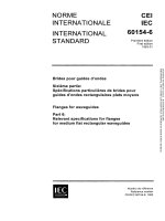
u
Figure 1 - Courbe de réduction pour un thyristor
CE1 1 222/93
LICENSED TO MECON Limited. - RANCHI/BANGALORE
FOR INTERNAL USE AT THIS LOCATION ONLY, SUPPLIED BY BOOK SUPPLY BUREAU.
4.6
747-6-3 © I EC: 1993
–
15 –
Value
Symbol
Limiting values
Subclause
min.
max.
Gate rating: [Any condition such as time, frequency,
temperature, mounting method, etc. shall be stated]
4.6.1
Peak forward gate voltage, where appropriate.
Anode positive with respect to cathode
VFGM1
X
4.6.1
Peak forward gate voltage, where applicable.
Anode negative with respect to cathode
VFGM2
x
4.6.3
Peak reverse gate voltage
VRGM
x
4.6.4
Peak forward gate current
/FGM
x
4.6.5
Peak gate power
PGM
x
4.6.6
Mean gate power
PGM(AV)
x
Mechanical ratings
4.7
Mounting torque (if applicable)
x
x
Mounting force (if applicable)
x
x
/T
Break point
/T(AV)
Tamb/Tcase
Tbreak
Tamb ^ Tcase
(max.)
Figure 1 – Current derating curve for a thyristor
IEC 1222/93
LICENSED TO MECON Limited. - RANCHI/BANGALORE
FOR INTERNAL USE AT THIS LOCATION ONLY, SUPPLIED BY BOOK SUPPLY BUREAU.
4.6
- 16 -
747-6-3 ©CEI:1993
5 Caractéristiques électriques
Voir l'article 8 de cette norme pour les exigences de contrôle.
[Répéter uniquement les numéros et titres des paragraphes utilisés. Mettre les caractéristiques supplémentaires éventuelles à l'endroit voulu, mais sans numéro de paragraphe.]
[Lorsque plusieurs dispositifs sont couverts par la même spécification particulière, il
convient d'indiquer les valeurs correspondantes sur des lignes successives, en évitant de
répéter les valeurs identiques.]
[Les courbes doivent de préférence figurer à l'article 10 de cette norme.]
Paragraphe
sauf spécification contraire (voir l'article 4
de la spécification générique)
5.1
Tension à l'état passant: Valeur maximale pour
un courant de pointe égal à n fois la valeur limite
du courant moyen à l'état passant /T(Av)
5.2
Courant inverse: Valeur maximale du courant
inverse de pointe répétitif pour la valeur limite de
la tension inverse de pointe répétitive VRRM :
5.2.1
à Tamb / TTSe = 25
5.2.2
a
5.3
amb / Case
°C
(max.)
Valeur
Symbole
Essayé
min.
max.
VTM
X
A2b
/ RRM1
x
A2b
/ RRM2
X
C2b
x
A2b
Courant à l'état bloqué: Valeur maximale de pointe
répétitif à l'état bloqué pour la valeur limite de la
tension de pointe répétitive à l'état bloqué VDRM:
5.3.1
à Tamb / Case = 25 °C
/ DRM 1
x
A2b
5.3.2
a Tamb/Tcase (max.)
I DRM2
x
C2b
X
C2a
lL
x
C2a
5.4
Courant de maintien: Valeurs minimale et maximale
5.5
Courant d'accrochage: Valeur maximale dans
des conditions spộcifiộes
5.6
Courant d'amorỗage par la gõchette: Valeur
maximale
/GT
x
A3
5.7
Tension d'amorỗage par la gõchette: Valeur
maximale
VGT
x
A3
5.8
Tension de non-amorỗage par la gâchette: Valeur
minimale
VGD
x
A4
5.9
Vitesse critique de croissance de la tension à
l'état bloqué (s'il y a lieu): Valeur minimale dans
des conditions spécifiées
(d VD/dt) cr
x
A4
5.10
Temps de dộsamorỗage par commutation du
circuit (pour les types à commutation rapide
seulement): Valeur maximale dans des conditions
spécifiées
/1-I
tq
x
x
C2c
LICENSED TO MECON Limited. - RANCHI/BANGALORE
FOR INTERNAL USE AT THIS LOCATION ONLY, SUPPLIED BY BOOK SUPPLY BUREAU.
Caractéristiques et conditions
à Tamb ou Tcase = 25 °C
747-6-3 ©IEC: 1993
- 17 -
5 Electrical characteristics
See clause 8 of this standard for inspection requirements.
[Repeat only subclause numbers used, with title. Any additional characteristics should be
given at the appropriate place but without subclause number.]
[When several devices are defined in the same detail specification, the relevant values
should be given on successive lines, avoiding repeating identical values.]
[Curves should preferably be given under clause 10 of this standard.]
unless otherwise specified
(see clause 4 of the generic specification)
5.1
On-state voltage: Maximum value at the peak
current corresponding to n times the rated
maximum mean on-state current /T(AV)
5.2
Reverse current: Maximum value of the repetitive
peak reverse current at rated repetitive peak
reverse voltage VRRM
Valûe
Symbol
Tested
min.
max.
VTM
x
A2b
5.2.1
at Tamb/Tcase = 25 °C
I RRM1
x
A2b
5.2.2
at cmb/Tcase (max.)
IRRM2
x
C2b
x
A2b
5.3
Off-state current: Maximum value of the repetitive
peak off-state current at rated repetitive peak offstate voltage VDRM:
5.3.1
at âmb / case = 25 ° C
IDRM1
x
A2b
5.3.2
at Tamb/ case (max.)
/DRM2
x
C2b
x
C2a
5.4
Holding current: Minimum and maximum values
IH
5.5
Latching current: Maximum value under specified
conditions
lL
x
C2a
5.6
Gate trigger current: Maximum value
IGT
x
A3
5.7
Gate trigger voltage: Maximum value
VGT
x
A3
5.8
Gate non-trigger voltage: Minimum value
VGD
x
A4
5.9
Critical rate of rise of off-state voltage (where
appropriate): Minimum value under specified
conditions
(d VD/dt) cr
x
A4
5.10
Circuit commutated turn-off time (for fastswitching type only): Maximum value under
specified conditions
tq
x
x
C2c
LICENSED TO MECON Limited. - RANCHI/BANGALORE
FOR INTERNAL USE AT THIS LOCATION ONLY, SUPPLIED BY BOOK SUPPLY BUREAU.
Subclause
Characteristics and conditions
at Tamb
T
or Tcase = 25 °C
- 18 -
Caractéristiques et conditions
à Ta m b ou Tcage = 25 °C
Paragraphe
sauf spécification contraire (voir l'article 4
de la spécification générique)
5.11
Dissipation de puissance totale: Courbe de la
dissipation de puissance totale maximale en
fonction du courant moyen à l'état passant et
de l'angle de conduction
5.12
Résistance thermique (si Tm) est spécifié en 4.3):
Jonction-ambiante ou jonction-boợtier valeur
maximale
747-6-3 â CEI:1993
Valeur
Symbole
Essayộ
min.
max.
Pt ct
x
RthJA
x
C2d
ou
RthJc
5.13
Temps d'amorỗage parla gõchette: Valeur maximale
dans les conditions spécifiées
tgt
5.14
Charge recouvrée: Valeur maximale ou valeurs
maximale et minimale dans les conditions
spécifiées
Qr
5.15
Courant de pointe de recouvrement inverse (si
approprié): Valeur maximale dans les conditions
spécifiées
/RM
x
5.16
Temps de recouvrement inverse (si approprié):
Valeur maximale dans les conditions spécifiées
trr
x
x
x
NOTE 1 – Si approprié.
6 Marquage
[Préciser ici tous les renseignements particuliers autres que ceux de la case [7] (article 1)
et/ou de 2.5 de la spécification générique.]
7 Renseignements à donner dans les commandes
[Sauf spécification contraire, les renseignements suivants constituent le minimum nécessaire pour passer commande d'un dispositif donné:
référence précise du modèle (et valeur de la tension nominale, si nécessaire);
référence IECQ de la spécification particulière avec numéro d'édition et/ou date
selon le cas;
- catégorie d'assurance de la qualité définie en 3.7 de la spécification intermédiaire
et, si nécessaire, séquence de sélection définie en 3.6 de cette même spécification;
- toute autre particularité.]
8 Conditions d'essai et exigences de contrôle
[Elles figurent dans les tableaux suivants, où il convient de spécifier les valeurs et les
conditions d'essai exactes à utiliser pour un modèle donné, conformément aux essais
correspondants indiqués dans la publication applicable.]
[Le choix entre les méthodes d'essais ou les variantes doit être fait lors de la rédaction de
la spécification particulière.]
LICENSED TO MECON Limited. - RANCHI/BANGALORE
FOR INTERNAL USE AT THIS LOCATION ONLY, SUPPLIED BY BOOK SUPPLY BUREAU.
x
(note 1)
747-6-3 ©IEC: 1993
Subclause
- 19 -
Characteristics and conditions
at Tamb or Tcase = 25 °C.
unless otherwise specified
(see clause 4 of the generic specification)
Value
Symbol
Tested
min.
5.11
Total power dissipation: The maximum total power
dissipation graph as a function of the mean onstate current and conduction angle
5.12
Thermal resistance (if To,i) is specified in 4.3):
Junction-to-ambient or junction-to-case maximum
value
5.13
Gate controlled turn-on time: Maximum value under
specified conditions
ttt
5.14
Recovered charge: Maximum value or maximum
and minimum values under specified conditions
Qr
5.15
Peak reverse recovery current (where appropriate):
Maximum value under specified conditions
IRM
5.16
Reverse recovery time (where appropriate):
Maximum value under specified conditions
max.
x
Ptot
x
RthJA
or
C2d
RthJc
x
trr
x
x
x
NOTE 1 – Where appropriate.
6 Marking
[Any particular information other than that given in box [7] (clause 1) and/or 2.5 of the
generic specification shall be given here.]
7 Ordering information
[The following minimum information is necessary to order a specific device, unless otherwise specified:
-
precise type reference (and nominal voltage value, if required);
- IECQ reference of detail specification with issue number and/or date when relevant;
- category of assessed quality as defined in 3.7 of the sectional specification and, if
required, screening sequence as defined in 3.6 of the sectional specification;
-
any other particulars.]
8 Test conditions and inspection requirements
[These are given in the following tables, where the values and exact test conditions to be
used shall be specified as required for a given type, and as required by the relevant test in
the relevant publication.]
[The choice between alternative tests or test methods shall be made when a detail
specification is written.]
LICENSED TO MECON Limited. - RANCHI/BANGALORE
FOR INTERNAL USE AT THIS LOCATION ONLY, SUPPLIED BY BOOK SUPPLY BUREAU.
x
(note 1)
–
20 –
747-6-3 © CEI:1993
[Lorsque plusieurs dispositifs sont couverts par la même spécification particulière, il
convient d'indiquer les conditions et/ou les valeurs correspondantes sur des lignes
successives, en évitant autant que possible de répéter les conditions et/ou les valeurs
identiques.]
Sauf indication contraire, les numéros de paragraphe donnés en référence dans cet article
renvoient à la spécification générique; les méthodes d'essai sont indiquées à l'article 4 de
la spécification intermédiaire.
[Les essais du groupe A doivent être effectués sur tous les dispositifs. Les essais du
groupe B doivent être effectués lot par lot, avec un prélèvement et NQT = 30.
Les essais du groupe C et D doivent être effectués avec un prélèvement et NQT = 50.]
Aucun essai n'est destructif (3.6.6)
Examen ou essai
Exam
Symbole
Conditions à Tamb ou Tcase = 25 °C
sauf spécification contraire
Référence
(voir l'article 4 de la spécification
générique)
Limites des exigences
de contrôle
max.
min.
Sous-groupe Al
4.2.1.1
Examen visuel externe
Sous-groupe A2a
Polarité inversée,
ou VTM > 10 LSS
Inopérantes
ou
100 LSS
1RRMt>
[sauf spécification
contraire]
Sous-groupe A2b
VTM
T-101
Courant inverse d
pointe répétitif
I RRM1
T-102
Courant de pointe
l'état bloqué répétitif
'DAM1
T-103
x
Courant d'amorỗage par
la gõchette
IUT
T-109
x
Tension d'amorỗage par
la gõchette
VGT
T-109
(dvp/dt)cr
T-112
Tension de pointe
l'ộtat passant
x
Voir article 5
x
Sous-groupe A3
Voir article 5
x
Sous-groupe A4
Vitesse critique de croissance de la tension à
l'état bloqué, s'il y a lieu
Tension de non-amorgage par la gâchette
x
Voir article 5
VGD
T-110
x
LICENSED TO MECON Limited. - RANCHI/BANGALORE
FOR INTERNAL USE AT THIS LOCATION ONLY, SUPPLIED BY BOOK SUPPLY BUREAU.
GROUPE A
Contrôles lot par lot
- 21 -
747-6-3 © IEC: 1993
[When several devices are included in the same detail specification, the relevant
conditions and/or values shall be given on successive lines, where possible avoiding
repetition of identical conditions and/or values.]
In this clause, reference to clause numbers are made with respect to the generic specification unless otherwise stated and test methods are quoted from clause 4 of the
sectional specification.
[Group A inspection and tests shall be performed on all devices. Group B inspection and
tests shall be performed on a lot-by-lot basis, sampling of an LTPD = 30.
Group C and D inspections and tests shall be performed on an LTPD = 50.]
All tests are non-destructive (3.6.6)
Inspection or test
Symbol
Reference
Conditions at amb or Tcase = 25 °C
unless otherwise specified
(see clause 4 of the generic
specification)
Inspection
requirement limits
min.
max.
Sub-group Al
External visual examination
4.2.1.1
Sub-group A2a
Inoperatives
Inverted polarity
or VTM > 10 USL
or
/RRMl> 100 USL
[unless otherwise
spec fied]
Sub-group A2b
Peak on-state voltage
VTM
T-101
Repetitive peak revers
current
IRRMt
T-102
Repetitive peak off-state
current
IDRMi
T-103
!GT
T-109
x
x
See clause 5
x
Sub-group A3
Gate trigger current
x
See clause 5
VGT
T-109
Critical rate of rise of
off-state voltage, where
applicable
(dv0/dt)cr
T-112
Gate non-trigger voltage
VGD
Gate trigger voltage
x
Sub-group A4
x
See clause 5
T-110
x
LICENSED TO MECON Limited. - RANCHI/BANGALORE
FOR INTERNAL USE AT THIS LOCATION ONLY, SUPPLIED BY BOOK SUPPLY BUREAU.
GROUP A
Lot-by-lot
747-6-3 © CEI:1993
- 22 GROUPE B
Contrơles lot par lot
(dans le cas de la catégorie 1, voir 2.6 de la spécification générique)
LIS = limite inférieure de la spécification } du groupe A
LSS = limite supérieure de la spécification J
Seuls les essais marqués (D) sont destructifs (3.6.6)
Conditions à Tamb ou
Symbole
Examen ou essai
Sous-groupe B1
Dimensions
sauf spécification contraire
(voir l'article 4 de la spécification
générique)
Sous-groupe 84
Soudabilité
s'il y a lieu
Sous-groupe 85
Variations rapides de
température:
a) Btiers à cavité
Variations rapides de
température, suivies de:
– Essais électriques
max.
[Voir article 1
de cette norme]
Force = [voir 749, Il, 1.2]
Pas de détérioration
749, II,
2.1
[Comme spécifié; bain de soudure
de préférence]
749, III,
1.1
10 cycles
Etamage correct
Voir A2b et A3 Comme en A2b et A3
A spécifier
749, III,
7.3 ou 7.4
– Etanchéité, détection des micro-fuites
et
– Etanchéité, détection
des fuites franches
b) Btiers sans cavité et
avec cavité à scellement époxyde
Variations rapides de
température, suivies de:
– Examen visuel
externe
– Essai continu de
chaleur humide
68-2-17,
essai Qc
A spécifier
10 cycles
749, III,
1.1
747-10
4.2.1.1
Sévérité à spécifier
749,
24 h
Ill, 5C
Voir A2b et A3 Comme en A2b et A3
– Essais électriques
Sous-groupe B8
Endurance électrique
(168 h)
– courant inverse de
pointe répétitif
– courant de pointe
l'état bloqué répétitif
min.
749, II,
1.4
(D)
avec les mesures finales:
– tension de pointe à
l'état passant
Limites des exigences
de contrôle
747-6, V
Fonctionnement en blocage par
tension alternative ou fonctionnement électrique à haute température
[ iTlAVI = 80 % à 100 % de /T(AV) max.]
VTM
Comme en A2b
1,1 LSS
iRRMt
Comme en A2b
2 LSS
i DRMt
Comme en A2b
2 LSS
Informations par attributs pour B3, B4, B5 et B8.
LICENSED TO MECON Limited. - RANCHI/BANGALORE
FOR INTERNAL USE AT THIS LOCATION ONLY, SUPPLIED BY BOOK SUPPLY BUREAU.
749, Il,
12
e t/ou
Sous-groupe RCLA
25 °C
4.2.2
annexe B
Sous-groupe B3
Robustesse des sorties
Si applicable:
– Pliage
(D)
– Couple
Référence
casa =
747-6-3 © IEC: 1993
- 23 GROUP B
Lot-by-lot
(in the case of category 1, see 2.6 of the generic specification)
LSL = lower specification limit
USL = upper specification limit
from group A
Only tests marked (D) are destructive (3.6.6)
Inspection or test
In
Symbol
Sub-group B1
Dimensions
749, II,
1. 2
and/or
Inspection
requirement limits
min.
max.
[See clause 1 of
this standard]
Force = [see 749, II, 1.2]
Non damage
749, II,
1.4
(D)
Sub-group B4
Solderability,
where applicable
Sub-group B5
Rapid change of
temperature:
a) Cavity packages
Rapid change of
temperature followed by:
– Electrical tests
– Sealing, fine leak
detection
and
– Sealing, gross leak
detection
b) Non-cavity and epoxysealed cavity packages
749, II,
2.1
[As specified; solder bath preferred]
749, III,
1.1
10 cycles
See A2b and A3
749, II,
7.3 or 7.4
Rapid change of ternperature, followed by:
– External visual
examination
– Damp heat, steady
state
– Electrical tests
As in A2b and A3
To be specified
68-2-17,
test Qc
To be specified
749, III,
1.1
10 cycles
747-10
4.2.1.1
749,
Ill, 5C
See A2b and A3
Good wetting
Severity to be specified
24 h
As in A2b and A3
Sub-group B8
747-6, V
Electrical endurance
(168 h)
with final measurements:
– peak on-state voltage
– repetitive peak reverse
current
– repetitive peak offstate current
Sub-group CRRL
VTM
IARM1
IDRM1
.High-temperature a.c. blocking or
operating life [ IT(Av) = 80 % to 100 %
of /T(AV) max.]
As in A2b
1,1 USL
As in A2b
2 USL
As in A2b
2 USL
Attributes information for B3, B4, B5 and B8.
LICENSED TO MECON Limited. - RANCHI/BANGALORE
FOR INTERNAL USE AT THIS LOCATION ONLY, SUPPLIED BY BOOK SUPPLY BUREAU.
4.2.2
Appendix B
Sub-group B3
Robustness of terminations
Where applicable:
– Bending
(D)
– Torque
Reference
Conditions at Tamb or Tcase = 25 °C
unless otherwise specified
(see clause 4 of the generic
specification)