Iec 60728 3 2010
Bạn đang xem bản rút gọn của tài liệu. Xem và tải ngay bản đầy đủ của tài liệu tại đây (1.1 MB, 136 trang )
®
Edition 4.0
2010-12
INTERNATIONAL
STANDARD
NORME
INTERNATIONALE
colour
inside
Cable networks for television signals, sound signals and interactive services –
Part 3: Active wideband equipment for cable networks
IEC 60728-3:2010
Réseaux de distribution par câbles pour signaux de télévision, signaux de
radiodiffusion sonore et services interactifs –
Partie 3: Matériel actif à large bande pour réseaux de distribution par câbles
Copyrighted material licensed to BR Demo by Thomson Reuters (Scientific), Inc., subscriptions.techstreet.com, downloaded on Nov-28-2014 by James Madison. No further reproduction or distribution is permitted. Uncontrolled when printe
IEC 60728-3
Copyright © 2010 IEC, Geneva, Switzerland
All rights reserved. Unless otherwise specified, no part of this publication may be reproduced or utilized in any form or by
any means, electronic or mechanical, including photocopying and microfilm, without permission in writing from either IEC or
IEC's member National Committee in the country of the requester.
If you have any questions about IEC copyright or have an enquiry about obtaining additional rights to this publication,
please contact the address below or your local IEC member National Committee for further information.
Droits de reproduction réservés. Sauf indication contraire, aucune partie de cette publication ne peut être reproduite
ni utilisée sous quelque forme que ce soit et par aucun procédé, électronique ou mécanique, y compris la photocopie
et les microfilms, sans l'accord écrit de la CEI ou du Comité national de la CEI du pays du demandeur.
Si vous avez des questions sur le copyright de la CEI ou si vous désirez obtenir des droits supplémentaires sur cette
publication, utilisez les coordonnées ci-après ou contactez le Comité national de la CEI de votre pays de résidence.
IEC Central Office
3, rue de Varembé
CH-1211 Geneva 20
Switzerland
Email:
Web: www.iec.ch
About the IEC
The International Electrotechnical Commission (IEC) is the leading global organization that prepares and publishes
International Standards for all electrical, electronic and related technologies.
About IEC publications
The technical content of IEC publications is kept under constant review by the IEC. Please make sure that you have the
latest edition, a corrigenda or an amendment might have been published.
Catalogue of IEC publications: www.iec.ch/searchpub
The IEC on-line Catalogue enables you to search by a variety of criteria (reference number, text, technical committee,…).
It also gives information on projects, withdrawn and replaced publications.
IEC Just Published: www.iec.ch/online_news/justpub
Stay up to date on all new IEC publications. Just Published details twice a month all new publications released. Available
on-line and also by email.
Electropedia: www.electropedia.org
The world's leading online dictionary of electronic and electrical terms containing more than 20 000 terms and definitions
in English and French, with equivalent terms in additional languages. Also known as the International Electrotechnical
Vocabulary online.
Customer Service Centre: www.iec.ch/webstore/custserv
If you wish to give us your feedback on this publication or need further assistance, please visit the Customer Service
Centre FAQ or contact us:
Email:
Tel.: +41 22 919 02 11
Fax: +41 22 919 03 00
A propos de la CEI
La Commission Electrotechnique Internationale (CEI) est la première organisation mondiale qui élabore et publie des
normes internationales pour tout ce qui a trait à l'électricité, à l'électronique et aux technologies apparentées.
A propos des publications CEI
Le contenu technique des publications de la CEI est constamment revu. Veuillez vous assurer que vous possédez
l’édition la plus récente, un corrigendum ou amendement peut avoir été publié.
Catalogue des publications de la CEI: www.iec.ch/searchpub/cur_fut-f.htm
Le Catalogue en-ligne de la CEI vous permet d’effectuer des recherches en utilisant différents critères (numéro de référence,
texte, comité d’études,…). Il donne aussi des informations sur les projets et les publications retirées ou remplacées.
Just Published CEI: www.iec.ch/online_news/justpub
Restez informé sur les nouvelles publications de la CEI. Just Published détaille deux fois par mois les nouvelles
publications parues. Disponible en-ligne et aussi par email.
Electropedia: www.electropedia.org
Le premier dictionnaire en ligne au monde de termes électroniques et électriques. Il contient plus de 20 000 termes et
définitions en anglais et en franỗais, ainsi que les termes ộquivalents dans les langues additionnelles. Egalement appelé
Vocabulaire Electrotechnique International en ligne.
Service Clients: www.iec.ch/webstore/custserv/custserv_entry-f.htm
Si vous désirez nous donner des commentaires sur cette publication ou si vous avez des questions, visitez le FAQ du
Service clients ou contactez-nous:
Email:
Tél.: +41 22 919 02 11
Fax: +41 22 919 03 00
Copyrighted material licensed to BR Demo by Thomson Reuters (Scientific), Inc., subscriptions.techstreet.com, downloaded on Nov-28-2014 by James Madison. No further reproduction or distribution is permitted. Uncontrolled when printe
THIS PUBLICATION IS COPYRIGHT PROTECTED
®
Edition 4.0
2010-12
INTERNATIONAL
STANDARD
NORME
INTERNATIONALE
colour
inside
Cable networks for television signals, sound signals and interactive services –
Part 3: Active wideband equipment for cable networks
Réseaux de distribution par câbles pour signaux de télévision, signaux de
radiodiffusion sonore et services interactifs –
Partie 3: Matériel actif à large bande pour réseaux de distribution par câbles
INTERNATIONAL
ELECTROTECHNICAL
COMMISSION
COMMISSION
ELECTROTECHNIQUE
INTERNATIONALE
PRICE CODE
CODE PRIX
ICS 33.060.40; 33.170
® Registered trademark of the International Electrotechnical Commission
Marque déposée de la Commission Electrotechnique Internationale
XB
ISBN 978-2-88912-576-0
Copyrighted material licensed to BR Demo by Thomson Reuters (Scientific), Inc., subscriptions.techstreet.com, downloaded on Nov-28-2014 by James Madison. No further reproduction or distribution is permitted. Uncontrolled when printe
IEC 60728-3
60728-3 IEC:2010
CONTENTS
FOREWORD ........................................................................................................................... 6
INTRODUCTION ..................................................................................................................... 8
1
Scope ............................................................................................................................... 9
2
Normative references ....................................................................................................... 9
3
Terms, definitions, symbols and abbreviations ................................................................ 11
4
3.1 Terms and definitions ............................................................................................ 11
3.2 Symbols ................................................................................................................ 15
3.3 Abbreviations ........................................................................................................ 16
Methods of measurement ............................................................................................... 17
4.1
4.2
4.3
4.4
4.5
4.6
4.7
4.8
4.9
General ................................................................................................................. 17
Linear distortion .................................................................................................... 18
4.2.1 Return loss ................................................................................................ 18
4.2.2 Flatness .................................................................................................... 19
4.2.3 Chrominance/luminance delay inequality for PAL/SECAM only .................. 19
Non-linear distortion .............................................................................................. 20
4.3.1 General ..................................................................................................... 20
4.3.2 Types of measurements ............................................................................ 20
4.3.3 Intermodulation.......................................................................................... 20
4.3.4 Composite triple beat ................................................................................. 22
4.3.5 Composite second order beat .................................................................... 25
4.3.6 Composite crossmodulation ....................................................................... 26
4.3.7 Method of measurement of non-linearity for pure digital channel load ........ 29
4.3.8 Hum modulation of carrier ......................................................................... 29
Automatic gain and slope control step response .................................................... 33
4.4.1 Definitions ................................................................................................. 33
4.4.2 Equipment required ................................................................................... 33
4.4.3 Connection of equipment ........................................................................... 34
4.4.4 Measurement procedure ............................................................................ 34
Noise figure ........................................................................................................... 35
4.5.1 General ..................................................................................................... 35
4.5.2 Equipment required ................................................................................... 35
4.5.3 Connection of equipment ........................................................................... 35
4.5.4 Measurement procedure ............................................................................ 35
Crosstalk attenuation............................................................................................. 36
4.6.1 Crosstalk attenuation for loop through ports .............................................. 36
4.6.2 Crosstalk attenuation for output ports ........................................................ 36
Signal level for digitally modulated signals ............................................................ 38
Measurement of composite intermodulation noise ratio (CINR) .............................. 38
4.8.1 General ..................................................................................................... 38
4.8.2 Equipment required ................................................................................... 38
4.8.3 Connection of equipment ........................................................................... 39
4.8.4 Measurement procedure ............................................................................ 40
4.8.5 Presentation of the results ......................................................................... 40
Immunity to surge voltages .................................................................................... 41
4.9.1 General ..................................................................................................... 41
4.9.2 Equipment required ................................................................................... 42
Copyrighted material licensed to BR Demo by Thomson Reuters (Scientific), Inc., subscriptions.techstreet.com, downloaded on Nov-28-2014 by James Madison. No further reproduction or distribution is permitted. Uncontrolled when printe
–2–
5
–3–
4.9.3 Connection of equipment ........................................................................... 42
4.9.4 Measurement procedure ............................................................................ 42
Equipment requirements ................................................................................................. 42
5.1
5.2
5.3
5.4
5.5
5.6
5.7
5.8
5.9
5.10
5.11
5.12
5.13
5.14
5.15
5.16
5.17
5.18
General requirements ............................................................................................ 42
Safety ................................................................................................................... 43
Electromagnetic compatibility (EMC) ..................................................................... 43
Frequency range ................................................................................................... 43
Impedance and return loss .................................................................................... 43
Gain ...................................................................................................................... 44
5.6.1 Minimum and maximum gain ..................................................................... 44
5.6.2 Gain control ............................................................................................... 44
5.6.3 Slope and slope control ............................................................................. 44
Flatness ................................................................................................................ 44
Test points ............................................................................................................ 45
Group delay .......................................................................................................... 45
5.9.1 Chrominance/luminance delay inequality ................................................... 45
5.9.2 Chrominance/luminance delay inequality for other television
standards and modulation systems ............................................................ 45
Noise figure ........................................................................................................... 45
Non-linear distortion .............................................................................................. 45
5.11.1 General ..................................................................................................... 45
5.11.2 Second order distortion ............................................................................. 45
5.11.3 Third order distortion ................................................................................. 45
5.11.4 Composite triple beat ................................................................................. 46
5.11.5 Composite second order ............................................................................ 46
5.11.6 Composite crossmodulation ....................................................................... 46
5.11.7 Maximum operating level for pure digital channel load ............................... 46
Automatic gain and slope control ........................................................................... 46
Hum modulation .................................................................................................... 46
Power supply ......................................................................................................... 46
Environmental ....................................................................................................... 47
5.15.1 General ..................................................................................................... 47
5.15.2 Storage (simulated effects of) .................................................................... 47
5.15.3 Transportation ........................................................................................... 47
5.15.4 Installation or maintenance ........................................................................ 47
5.15.5 Operation .................................................................................................. 47
5.15.6 Energy efficiency of equipment .................................................................. 47
Marking ................................................................................................................. 47
5.16.1 Marking of equipment ................................................................................ 47
5.16.2 Marking of ports ........................................................................................ 47
Mean operating time between failure (MTBF) ........................................................ 48
Requirements for multi-switches ............................................................................ 48
5.18.1 Control signals for multi-switches .............................................................. 48
5.18.2 Amplitude frequency response flatness ...................................................... 48
5.18.3 Return loss ................................................................................................ 48
5.18.4 Through loss ............................................................................................. 48
5.18.5 Isolation .................................................................................................... 48
5.18.6 Crosstalk attenuation ................................................................................. 48
5.18.7 Satellite IF to terrestrial signal isolation ..................................................... 48
Copyrighted material licensed to BR Demo by Thomson Reuters (Scientific), Inc., subscriptions.techstreet.com, downloaded on Nov-28-2014 by James Madison. No further reproduction or distribution is permitted. Uncontrolled when printe
60728-3 IEC:2010
60728-3 IEC:2010
5.19 Immunity to surge voltages .................................................................................... 49
5.19.1 Degrees of testing levels ........................................................................... 49
5.19.2 Recommendation of testing level degree ................................................... 49
Annex A (informative) Derivation of non-linear distortion ...................................................... 50
Annex B (normative) Test carriers, levels and intermodulation products ............................... 52
Annex C (normative) Checks on test equipment ................................................................... 54
Annex D (informative) Test frequency plan for composite triple beat (CTB), composite
second order (CSO) and crossmodulation (XM) measurement .............................................. 55
Annex E (informative) Measurement errors which occur due to mismatched equipment ....... 56
Annex F (informative) Examples of signals, methods of measurement and network
design for return paths .......................................................................................................... 57
Bibliography .......................................................................................................................... 64
Figure 1 – Maximum error a for measurement of return loss using VSWR-bridge with
directivity D = 46 dB and 26 dB test port return loss .............................................................. 18
Figure 2 – Measurement of return loss .................................................................................. 19
Figure 3 – Basic arrangement of test equipment for evaluation of the ratio of signal to
intermodulation product ........................................................................................................ 21
Figure 4 – Connection of test equipment for the measurement of non-linear distortion
by composite beat ................................................................................................................. 24
Figure 5 – Connection of test equipment for the measurement of composite
crossmodulation.................................................................................................................... 28
Figure 6 – Carrier/hum ratio .................................................................................................. 30
Figure 7 – Test set-up for local-powered objects ................................................................... 31
Figure 8 – Test set-up for remote-powered objects ............................................................... 31
Figure 9 – Oscilloscope display ............................................................................................ 32
Figure 10 – Time constant T c ................................................................................................ 33
Figure 11 – Measurement of AGC step response .................................................................. 34
Figure 12 – Measurement of noise figure .............................................................................. 35
Figure 13 – Measurement of crosstalk attenuation for loop trough ports of multiswitches ............................................................................................................................... 37
Figure 14 – Characteristic of the noise filter .......................................................................... 39
Figure 15 – Test setup for the non-linearity measurement ..................................................... 39
Figure 16 – Presentation of the result of CINR ...................................................................... 41
Figure 17 – Measurement set-up for surge immunity test ...................................................... 42
Figure B.1 – An example showing products formed when 2ƒ a > ƒ b ....................................... 52
Figure B.2 – An example showing products formed when 2ƒ a < ƒ b ...................................... 53
Figure B.3 – Products of the form ƒ a ± ƒb ± ƒc .................................................................. 53
Figure E.1 – Error concerning return loss measurement ........................................................ 56
Figure E.2 – Maximum ripple ................................................................................................ 56
Figure F.1 – Spectrum of a QPSK-modulated signal ............................................................. 57
Figure F.2 – Measurement of non-linearity using wideband noise ......................................... 59
Figure F.3 – Network used in the design example ................................................................. 60
Figure F.4 – A test result measured from a real 20 dB return amplifier .................................. 61
Figure F.5 – The CINR curve of one amplifier is modified to represent the CINR of the
whole coaxial section of the network ..................................................................................... 62
Copyrighted material licensed to BR Demo by Thomson Reuters (Scientific), Inc., subscriptions.techstreet.com, downloaded on Nov-28-2014 by James Madison. No further reproduction or distribution is permitted. Uncontrolled when printe
–4–
–5–
Figure F.6 – The CINR of an optical link as a function of OMI, example ................................. 63
Table 1 – Correction factors where the modulation used is other than 100 % ........................ 26
Table 2 – Notch filter frequencies ......................................................................................... 39
Table 3 – Return loss requirements for all equipment ........................................................... 44
Table 4 – Parameters of surge voltages for different degrees of testing levels ...................... 49
Table 5 – Recommendations for degree of testing levels ...................................................... 49
Table D.1 – Frequency allocation plan .................................................................................. 55
Table F.1 – Application of methods of measurement in IEC 60728-3 for return path
equipment ............................................................................................................................. 58
Table F.2 – Application of methods of measurement in IEC 60728-6 for return path
equipment ............................................................................................................................. 58
Copyrighted material licensed to BR Demo by Thomson Reuters (Scientific), Inc., subscriptions.techstreet.com, downloaded on Nov-28-2014 by James Madison. No further reproduction or distribution is permitted. Uncontrolled when printe
60728-3 IEC:2010
60728-3 IEC:2010
INTERNATIONAL ELECTROTECHNICAL COMMISSION
____________
CABLE NETWORKS FOR TELEVISION SIGNALS,
SOUND SIGNALS AND INTERACTIVE SERVICES –
Part 3: Active wideband equipment for cable networks
FOREWORD
1) The International Electrotechnical Commission (IEC) is a worldwide organization for standardization comprising
all national electrotechnical committees (IEC National Committees). The object of IEC is to promote international co-operation on all questions concerning standardization in the electrical and electronic fields. To this
end and in addition to other activities, IEC publishes International Standards, Technical Specifications, Technical Reports, Publicly Available Specifications (PAS) and Guides (hereafter referred to as “IEC Publication(s)”). Their preparation is entrusted to technical committees; any IEC National Committee interested in the
subject dealt with may participate in this preparatory work. International, governmental and non-governmental
organizations liaising with the IEC also participate in this preparation. IEC collaborates closely with the International Organization for Standardization (ISO) in accordance with conditions determined by agreement between
the two organizations.
2) The formal decisions or agreements of IEC on technical matters express, as nearly as possible, an international
consensus of opinion on the relevant subjects since each technical committee has representation from all interested IEC National Committees.
3) IEC Publications have the form of recommendations for international use and are accepted by IEC National
Committees in that sense. W hile all reasonable efforts are made to ensure that the technical content of IEC
Publications is accurate, IEC cannot be held responsible for the way in which they are used or for any misinterpretation by any end user.
4) In order to promote international uniformity, IEC National Committees undertake to apply IEC Publications
transparently to the maximum extent possible in their national and regional publications. Any divergence between any IEC Publication and the corresponding national or regional publication shall be clearly indicated in
the latter.
5) IEC itself does not provide any attestation of conformity. Independent certification bodies provide conformity
assessment services and, in some areas, access to IEC marks of conformity. IEC is not responsible for any
services carried out by independent certification bodies.
6) All users should ensure that they have the latest edition of this publication.
7) No liability shall attach to IEC or its directors, employees, servants or agents including individual experts and
members of its technical committees and IEC National Committees for any personal injury, property damage or
other damage of any nature whatsoever, whether direct or indirect, or for costs (including legal fees) and expenses arising out of the publication, use of, or reliance upon, this IEC Publication or any other IEC Publications.
8) Attention is drawn to the Normative references cited in this publication. Use of the referenced publications is
indispensable for the correct application of this publication.
9) Attention is drawn to the possibility that some of the elements of this IEC Publication may be the subject of patent rights. IEC shall not be held responsible for identifying any or all such patent rights.
International Standard IEC 60728-3 has been prepared by technical area 5: Cable networks
for television signals, sound signals and interactive services, of IEC technical committee 100:
Audio, video and multimedia systems and equipment.
This fourth edition cancels and replaces the third edition published in 2005 of which it constitutes a technical revision.
This edition includes the following significant technical changes with respect to the previous
edition:
•
extension of upper frequency range limit for cable network equipment from 862 MHz to
1 000 MHz;
•
method of measurement and requirements for immunity to surge voltages;
•
extension of scope to equipment using symmetrical ports;
•
additional normative references;
Copyrighted material licensed to BR Demo by Thomson Reuters (Scientific), Inc., subscriptions.techstreet.com, downloaded on Nov-28-2014 by James Madison. No further reproduction or distribution is permitted. Uncontrolled when printe
–6–
•
–7–
additional terms and definitions and abbreviations.
This bilingual version, published in 2011-07, corresponds to the English version.
The text of this standard is based on the following documents:
FDIS
Report on voting
100/1746/FDIS
100/1766/RVD
Full information on the voting for the approval of this standard can be found in the report on
voting indicated in the above table.
The French version of this standard has not been voted upon.
This publication has been drafted in accordance with the ISO/IEC Directives, Part 2.
The list of all the parts of the IEC 60728 series, under the general title Cable networks for television signals, sound signals and interactive services, can be found on the IEC website.
The committee has decided that the contents of this publication will remain unchanged until
the stability date indicated on the IEC web site under "" in the data related to the specific publication. At this date, the publication will be
•
•
•
•
reconfirmed,
withdrawn,
replaced by a revised edition, or
amended.
IMPORTANT – The 'colour inside' logo on the cover page of this publication indicates
that it contains colours which are considered to be useful for the correct understanding of its contents. Users should therefore print this document using a colour printer.
Copyrighted material licensed to BR Demo by Thomson Reuters (Scientific), Inc., subscriptions.techstreet.com, downloaded on Nov-28-2014 by James Madison. No further reproduction or distribution is permitted. Uncontrolled when printe
60728-3 IEC:2010
60728-3 IEC:2010
INTRODUCTION
Standards of the IEC 60728 series deal with cable networks including equipment and associated methods of measurement for headend reception, processing and distribution of television
signals, sound signals and their associated data signals and for processing, interfacing and
transmitting all kinds of signals for interactive services using all applicable transmission media.
This includes
•
CATV 1-networks;
•
MATV-networks and SMATV-networks;
•
individual receiving networks;
and all kinds of equipment, systems and installations installed in such networks.
For active equipment with balanced RF signal ports this standard applies to those ports which
carry RF broadband signals for services as described in the scope of this standard.
The extent of this standardization work is from the antennas and/or special signal source inputs to the headend or other interface points to the network up to the terminal input.
The standardization of any user terminals (i.e., tuners, receivers, decoders, multimedia terminals, etc.) as well as of any coaxial, balanced and optical cables and accessories thereof is
excluded.
___________
1
This word encompasses the HFC (Hybrid Fibre Cable) networks used nowadays to provide telecommunications
services, voice, data, audio and video both broadcast and narrowcast.
Copyrighted material licensed to BR Demo by Thomson Reuters (Scientific), Inc., subscriptions.techstreet.com, downloaded on Nov-28-2014 by James Madison. No further reproduction or distribution is permitted. Uncontrolled when printe
–8–
–9–
CABLE NETWORKS FOR TELEVISION SIGNALS,
SOUND SIGNALS AND INTERACTIVE SERVICES –
Part 3: Active wideband equipment for cable networks
1
Scope
This part of IEC 60728 lays down the measuring methods, performance requirements and data publication requirements for active wideband equipment of cable networks for television
signals, sound signals and interactive services.
This standard
•
applies to all broadband amplifiers used in cable networks;
•
covers the frequency range 5 MHz to 3 000 MHz;
NOTE The upper limit of 3 000 MHz is an example, but not a strict value. The frequency range, or ranges, over
which the equipment is specified, should be published.
•
applies to one-way and two-way equipment;
•
lays down the basic methods of measurement of the operational characteristics of the active equipment in order to assess the performance of this equipment;
•
identifies the performance specifications to be published by the manufacturers;
•
states the minimum performance requirements of certain parameters.
Amplifiers are divided into the following two quality levels:
Grade 1:
amplifiers typically intended to be cascaded;
Grade 2:
amplifiers for use typically within an apartment block, or within a single residence,
to feed a few outlets.
Practical experience has shown that these types meet most of the technical requirements
necessary for supplying a minimum signal quality to the subscribers. This classification is not
a requirement but is provided to users and manufacturers for information about minimum
quality criteria of the material required to install networks of different sizes. The system operator has to select appropriate material to meet the minimum signal quality at the subscriber’s outlet, and to optimise cost/performance, taking into account the size of the network and
local circumstances.
All requirements and published data are understood as guaranteed values within the specified
frequency range and in well-matched conditions.
2
Normative references
The following referenced documents are indispensable for the application of this document.
For dated references, only the edition cited applies. For undated references, the latest edition
of the referenced document (including any amendments) applies.
IEC 60065,
Audio, video and similar electronic apparatus – Safety requirements
IEC 60068-1:1998,
IEC 60068-2-1,
Environmental testing – Part 1: General and guidance
Environmental testing – Part 2-1: Tests – Tests A: Cold
Copyrighted material licensed to BR Demo by Thomson Reuters (Scientific), Inc., subscriptions.techstreet.com, downloaded on Nov-28-2014 by James Madison. No further reproduction or distribution is permitted. Uncontrolled when printe
60728-3 IEC:2010
60728-3 IEC:2010
IEC 60068-2-2,
Environmental testing – Part 2-2: Tests – Tests B: Dry heat
IEC 60068-2-6,
Environmental testing – Part 2-6: Tests – Test Fc: Vibration (sinusoidal)
IEC 60068-2-14,
Environmental testing – Part 2-14: Tests – Test N: Change of temperature
IEC 60068-2-27,
Environmental testing – Part 2-27: Tests – Test Ea and guidance: Shock
IEC 60068-2-29,
guidance: Bump
Basic environmental testing procedures – Part 2-29: Tests – Test Eb and
IEC 60068-2-30, Environmental testing – Part 2-30: Tests – Test dB: Damp heat, cyclic
(12 h + 12 h cycle)
IEC 60068-2-31, Environmental testing – Part 2-31: Tests – Test Ec: Rough handling
shocks, primarily for equipment-type specimens
IEC 60068-2-32,
fall
Basic environmental testing procedures – Part 2-32: Tests – Test Ed: Free
IEC 60068-2-40, Basic environmental testing procedures – Part 2-40: Tests – Test Z/AM:
Combined cold/low air pressure tests
IEC 60068-2-48, Basic environmental testing procedures – Part 2-48: Tests – Guidance on
the application of the tests of IEC publication 60068 to simulate the effects of storage
IEC 60529,
Degrees of protection provided by enclosures (IP Code)
IEC 60728-1, Cable networks for television signals, sound signals and interactive services –
Part 1: System performance of forward paths
IEC 60728-2, Cable networks for television signals, sound signals and interactive services –
Part 2: Electromagnetic compatibility for equipment
IEC 60728-4, Cable networks for television signals, sound signals and interactive services –
Part 4: Passive wideband equipment for coaxial cable networks
IEC 60728-5, Cable networks for television signals, sound signals and interactive services –
Part 5: Headend equipment
IEC 60728-11, Cable networks for television signals, sound signals and interactive services – Part 11: Safety
IEC 60950-1,
Information technology equipment – Safety – Part 1: General requirements
IEC 61000-4-5, Electromagnetic compatibility (EMC) – Part 4-5: Testing and measurement
techniques – Surge immunity test
IEC 61319-1,
Interconnections of satellite receiving equipment – Part 1: Europe
IEC 61319-2,
Interconnections of satellite receiving equipment – Part 2: Japan
ITU-T Recommendation G.117, Transmission systems and media – Digital systems and networks – International telephone connections and circuits – General recommendations on the
transmission quality for an entire international telephone connection – Transmission aspects
of unbalance about earth
ITU-T Recommendation O.9, Specifications of measuring equipment – General – Measuring
arrangements to assess the degree of unbalance about earth
Copyrighted material licensed to BR Demo by Thomson Reuters (Scientific), Inc., subscriptions.techstreet.com, downloaded on Nov-28-2014 by James Madison. No further reproduction or distribution is permitted. Uncontrolled when printe
– 10 –
3
– 11 –
Terms, definitions, symbols and abbreviations
For the purposes of this document, the following terms, definitions, symbols and abbreviations
apply.
3.1
Terms and definitions
3.1.1
amplitude frequency response
gain or loss of an equipment or system plotted against frequency
3.1.2
attenuation
ratio of the input power to the output power of an equipment or system, usually expressed in
decibels
3.1.3
balun
device to match symmetrical impedance 100 Ω (balanced) to un-symmetrical impedance 75 Ω
(unbalanced) and vice-versa
3.1.4
carrier-to-noise ratio
difference in decibels between the vision or sound carrier level at a given point in an equipment or system and the noise level at that point (measured within a bandwidth appropriate to
the television or radio system in use)
3.1.5
chrominance-luminance delay inequality
difference in transmission delay of chrominance and luminance signals, which results in the
spilling of colour to left or right of the area of corresponding luminance
[IEC 60050-723:1997, 723-06-61]
3.1.6
composite intermodulation noise
CIN
sum of noise and intermodulation products from digital modulated signals
3.1.7
composite intermodulation noise ratio
CINR
ratio of the signal level and the CIN level
3.1.8
crossmodulation
undesired modulation of the carrier of a desired signal by the modulation of another signal as
a result of equipment or system non-linearities
3.1.9
crosstalk attenuation
unwanted signals beside the wanted signal on a lead caused by electromagnetic coupling between leads; ratio of the wanted signal power to the unwanted signal power, while equal signal powers are applied to the leads
NOTE
Crosstalk attenuation is usually expressed in decibels.
Copyrighted material licensed to BR Demo by Thomson Reuters (Scientific), Inc., subscriptions.techstreet.com, downloaded on Nov-28-2014 by James Madison. No further reproduction or distribution is permitted. Uncontrolled when printe
60728-3 IEC:2010
60728-3 IEC:2010
3.1.10
decibel ratio
ten times the logarithm of the ratio of two quantities of power P 1 and P 2 , i.e.
10lg
P1
P2
in dB
3.1.11
equaliser
device designed to compensate over a certain frequency range for the amplitude/frequency
distortion or phase/frequency distortion introduced by feeders or equipment
NOTE
This device is for the compensation of linear distortions only.
3.1.12
feeder
transmission path forming part of a cable network
NOTE Such a path may consist of a metallic cable, optical fibre, waveguide or any combination of them. By extension, the term is also applied to paths containing one or more radio links.
3.1.13
gain
ratio of the output power to the input power, usually expressed in decibels
3.1.14
ideal thermal noise
noise generated in a resistive component due to the thermal agitation of electrons
NOTE
The thermal power generated is given by
P = 4 ⋅ B ⋅ k ⋅T
where
P
is the noise power in watts;
B
is the bandwidth in hertz;
k
is the Boltzmann's constant = 1,38·10 –23 J/K;
T
is the absolute temperature in kelvins.
It follows that
U2
= 4 ⋅ B ⋅ k ⋅T
R
and
U = 4 ⋅ R ⋅ B ⋅ k ⋅T
where
U
is the noise voltage (e.m.f.);
R
is the resistance in ohms.
In practice, it is normal for the source to be terminated with a load equal to the internal resistance value, the noise
voltage at the input is then U/2.
3.1.15
level
decibel ratio of any power P 1 to the standard reference power P 0 , i.e.
Copyrighted material licensed to BR Demo by Thomson Reuters (Scientific), Inc., subscriptions.techstreet.com, downloaded on Nov-28-2014 by James Madison. No further reproduction or distribution is permitted. Uncontrolled when printe
– 12 –
– 13 –
P1
P0
10 lg
decibel ratio of any voltage U 1 to the standard reference voltage U 0 , i.e.
20 lg
U1
U0
NOTE The power level may be expressed in decibels relative to P 0 = (U 0 2 /R) = (1/75) pW, i.e. in dB(P 0 ), taking
into account that the level of P 0 corresponds to 0 dB(P 0 ) or, as more usually, in dB(pW ), taking into account that
the level of P 0 corresponds to –18,75 dB(pW ). The voltage level is expressed in decibels relative to 1 µV (across
75 Ω), i.e. in dB(µV).
3.1.16
modulation error ratio
MER
sum of the squares of the magnitudes of the ideal symbol vectors is divided by the sum of the
squares of the magnitudes of the symbol error vectors of a sequence of symbols, the result
being expressed as a power ratio in dB
∑(
)
N
I 2j + Q 2j
j =1
MER = 10 lg N
δI 2j + δQ 2j
j =1
∑(
)
in dB
3.1.17
multi-switch
equipment used in distribution systems for signals that are received from satellites and converted to a suitable IF
NOTE The IF signals that are received from different polarisations, frequency bands and orbital positions are input signals to the multi-switch. Subscriber feeders are connected to the multi-switch output ports. Each output port
is switched to one of the input ports, depending on control signals that are transmitted from the subscriber equipment to the multi-switch. Besides a splitter for each input port and a switch for each output port, a multi-switch can
contain amplifiers to compensate for distribution or cable losses.
3.1.18
multi-switch loop through port
one or more ports to loop through the input signals through a multi-switch
NOTE This enables larger networks with multiple multi-switches, each one installed close to a group of subscribers. The multi-switches are connected in a loop through manner. The IF signals that are received by an outdoor
unit from different polarisations, frequency bands and orbital positions are input signals to a first multi-switch. Cables connect the loop through ports of this multi-switch to the input ports of a second multi-switch and so on.
3.1.19
multi-switch port for terrestrial signals
port in a multi-switch used to distribute terrestrial signals in addition to the signals received
from satellites
3.1.20
noise factor/noise figure
used as figures of merit describing the internally generated noise of an active device
NOTE The noise factor, F, is the ratio of the carrier-to-noise ratio at the input, to the carrier-to-noise ratio at the
output of an active device.
Copyrighted material licensed to BR Demo by Thomson Reuters (Scientific), Inc., subscriptions.techstreet.com, downloaded on Nov-28-2014 by James Madison. No further reproduction or distribution is permitted. Uncontrolled when printe
60728-3 IEC:2010
F=
60728-3 IEC:2010
C1/N 1
C 2 /N 2
where
is the signal power at the input;
C1
C2
is the signal power at the output;
is the noise power at the input (ideal thermal noise);
N1
is the noise power at the output.
N2
In other words, the noise factor is the ratio of noise power at the output of an active device to the noise power at
the same point if the device had been ideal and added no noise.
F =
N 2 actual
N 2 ideal
The noise factor is dimensionless and is often expressed as noise figure, NF, in dB
NF = 10 lg F
in dB
3.1.21
slope
difference in gain or attenuation at two specified frequencies between any two points in an
equipment or system
NOTE
a)
b)
The slope sign is considered
negative when the attenuation increases with frequency (cables) or the gain (amplifiers) decreases with frequency,
positive when the gain (amplifiers) increases with frequency (compensating slope).
3.1.22
standard reference power and voltage
in cable networks, the standard reference power, P 0 , is (1/75) pW
NOTE 1
This is the power dissipated in a 75 Ω resistor with an RMS voltage drop of 1 µV across it.
NOTE 2
The standard reference voltage, U 0 , is 1 µV.
3.1.23
surge voltage
produced by a direct or indirect lightning stroke
3.1.24
well-matched
matching condition when the return loss of the equipment complies with the requirements of
Table 3
NOTE Through mismatching of measurement instruments and the measurement object, measurement errors are
possible. Comments to the estimation of such errors are given in Annex E.
Copyrighted material licensed to BR Demo by Thomson Reuters (Scientific), Inc., subscriptions.techstreet.com, downloaded on Nov-28-2014 by James Madison. No further reproduction or distribution is permitted. Uncontrolled when printe
– 14 –
3.2
– 15 –
Symbols
The following graphical symbols are used in the figures of this standard. These symbols are
either listed in IEC 60617 or based on symbols defined in IEC 60617.
Symbols
V
G
kT
G
A
x dB
Σ
Symbols
Amperemeter
based on
[IEC 60617-S00910
(2001-07)]
A
EUT
Terms
Selective voltmeter
Equipment Under Test
based on
[IEC 60617-S00059
(2001-07)]
Noise generator
[IEC 60617-S01230
(2001-07)]
Terms
V
Voltmeter
based on
[IEC 60617-S00910
(2001-07)]
W
Power meter
based on
[IEC 60617-S00910
(2001-07)]
G
Signal generator
based on
[IEC 60617-S00899,
IEC 60617-S01403
(2001-07)]
G
Variable signal generator
based on
[IEC 60617-S00081,
IEC 60617-S00899,
IEC 60617-S01403
(2001-09)]
Surge generator
[IEC 60617-S01228
(2001-07)]
VSWR-bridge
High-pass filter
[IEC 60617-S01247
(2001-07)]
Low-pass filter
[IEC 60617-S01248
(2001-07)]
Band-stop filter
[IEC 60617-S01250
(2001-07)]
Band-pass filter
[IEC 60617-S01249
(2001-07)]
Oscilloscope
based on
[IEC 60617-S00059, and
IEC 60617-S00922
(2001-07)]
P(f)
Spectrum analyzer
(electrical)
based on
[IEC 60617-S00910
(2001-07)]
A
Variable attenuator
[IEC 60617-S01245
(2001-07)]
Attenuator
based on
[IEC 60617-S01244
(2001-07)]
Combiner
based on
[IEC 60617-S00059
(2001-07)]
Double tap-off-box
Tap-off-box
O
E
Optical receiver
[IEC 60617-S00213
(2001-07)]
Copyrighted material licensed to BR Demo by Thomson Reuters (Scientific), Inc., subscriptions.techstreet.com, downloaded on Nov-28-2014 by James Madison. No further reproduction or distribution is permitted. Uncontrolled when printe
60728-3 IEC:2010
Symbols
Terms
Amplifier with return path
amplifier
[IEC 60617-S00433
(2001-07)]
Functional equipotential
bonding
[IEC 60617-S01410
(2001-11)]
Variable resistor
[IEC 60617-S00557
(2001-07)]
RF choke
[IEC 60617-S00583
(2001-07)]
3.3
Abbreviations
AC
alternating current
AF
audio frequency
AGC
automatic gain control
AM
amplitude modulation
BER
bit error ratio
CATV
community antenna television (system)
CIN
composite intermodulation noise
CINR
composite intermodulation noise ratio
CSO
composite second order
CTB
composite triple beat
CW
continuous wave
CXM
composite crossmodulation
DC
direct current
EMC
electromagnetic compatibility
EUT
equipment under test
HP
high pass
IF
intermediate frequency
IP
international protection
LF
low frequency
LP
low pass
MATV
master antenna television (system)
MER
modulation error ratio
MTBF
meantime between failure
OMI
optimum modulation index
PAL
phase alternating line
PID
packet identifier
PRBS
pseudo-random bit sequence
60728-3 IEC:2010
Symbols
Terms
Detector with LFamplifier
Adjustable AC voltage
source
Capacitor
[IEC 60617-S00567
(2001-07)]
Copyrighted material licensed to BR Demo by Thomson Reuters (Scientific), Inc., subscriptions.techstreet.com, downloaded on Nov-28-2014 by James Madison. No further reproduction or distribution is permitted. Uncontrolled when printe
– 16 –
– 17 –
QAM
quadrature amplitude modulation
QPSK
quadrature phase shift keying
RF
radio frequency
RMS
root mean square
RS
rotary switch
SECAM
sequential colour with memory (séquentiel couleur à mémoire)
SG
signal generator
SMATV
satellite master antenna television (system)
TV
television
UHF
ultra-high frequency
VHF
very-high frequency
VSWR
voltage standing wave ratio
XM
crossmodulation
4
4.1
Methods of measurement
General
This clause defines basic methods of measurement. Any equivalent method that ensures the
same accuracy may be used for assessing performance.
Unless stated otherwise, all measurements shall be carried out with 0 dB plug-in attenuators
and equalisers. The position of variable controls used during the measurements shall be published.
The test set-up shall be well-matched over the specified frequency band.
A network can be used to distribute terrestrial signals in addition to the signals received from
satellites. The terrestrial antennas are connected to an optional terrestrial input port of a multi-switch. On each output port the terrestrial signals are available in addition to the satellite IF
signals. Since the usual frequency ranges for terrestrial signals and satellite IF signals do not
overlap, both can be carried on the same cable.
For large networks with loop through connected multi-switches, two possibilities exist to carry
the terrestrial signals from one multi-switch to another multi-switch:
•
to use a specialised cable for the terrestrial signal, in addition with the cables used for the
satellite IF signals and then, on each output port the terrestrial signal is combined with the
selected satellite IF signal;
•
to combine the terrestrial signal with each satellite IF signal before the first multi-switch in
order to minimise the number of cables between multi-switches.
NOTE The signal coming from an outdoor unit for satellite reception may contain unwanted signal-components
with frequencies below the foreseen satellite IF frequency range. These signal-components overlap with the frequency range of terrestrial signals. For example, an outdoor unit that converts the frequency band 11,7 GHz to
12,75 GHz to the satellite IF frequency range may convert signals in the 10,7 GHz to 11,7 GHz band to frequencies
below the satellite IF frequency range. These frequencies have to be filtered out sufficiently to avoid interference
with terrestrial signals on the same cable.
For measurements on multi-switches, it is necessary that control signals be fed to the output
ports that are involved in the measurement. Therefore, a bias-tee has to be connected between the multi-switch output port and the measurement set. The DC port of the bias-tee is
connected to a standard receiver that generates the required control signals. Care has to be
taken that the influence of the bias-tee on the measurement result is insignificant. This can be
Copyrighted material licensed to BR Demo by Thomson Reuters (Scientific), Inc., subscriptions.techstreet.com, downloaded on Nov-28-2014 by James Madison. No further reproduction or distribution is permitted. Uncontrolled when printe
60728-3 IEC:2010
60728-3 IEC:2010
achieved by including it into the calibration or using a network analyzer with a built in biastee.
Measurements on active equipment with symmetrical ports shall be performed using a measurement balun. The symmetry (common mode suppression) of the output signal of such a
measurement balun shall be >30 dB for 100 MHz to 1 000 MHz and >50 dB for 30 MHz to
100 MHz. The common mode suppression shall be measured according to ITU-T Rec. G.117
and ITU-T Rec. O.9. The return loss of the measurement balun shall be 10 dB higher than the
return loss of the EUT to which the coaxial measurement equipment is connected via the
measurement balun.
4.2
Linear distortion
4.2.1
4.2.1.1
Return loss
General
The method described is applicable to the measurement of the return loss of equipment operating in the frequency range 5 MHz to 3 000 MHz.
All input and output ports of the unit shall meet the specification under all conditions of automatic and manual gain controls and with any combination of plug-in equalisers and attenuators fitted.
4.2.1.2
Equipment required
The following equipment is required.
a) A signal generator or sweep generator, adjustable over the frequency range of the equipment to be tested.
Care shall be taken to ensure that the signal generator or sweep generator output does
not have a high harmonic content as this can cause serious inaccuracy.
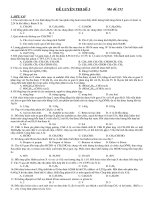
b) A voltage standing wave ratio bridge with built-in or separate RF detector.
The accuracy of measurement is dependent on the quality of the bridge. In particular on
the directivity and on the return loss of the test port of the bridge. For example Figure 1
shows the maximum accuracy achieved by a bridge with 46 dB directivity and 26 dB return
loss.
3 dB
Maximum error a
2 dB
D = 46 dB
1 dB
0
–1 dB
D = 46 dB
–2 dB
–3 dB
0 dB
10 dB
20 dB
Measured return loss
30 dB
40 dB
IEC 2501/10
Figure 1 – Maximum error a for measurement of return loss using VSWR-bridge
with directivity D = 46 dB and 26 dB test port return loss
Copyrighted material licensed to BR Demo by Thomson Reuters (Scientific), Inc., subscriptions.techstreet.com, downloaded on Nov-28-2014 by James Madison. No further reproduction or distribution is permitted. Uncontrolled when printe
– 18 –
– 19 –
c) An oscilloscope.
d) Calibrated mismatches.
NOTE The signal generator and the oscilloscope can be replaced by a spectrum analyzer and a tracking generator or by a network analyzer connected directly to the EUT.
4.2.1.3
Connection of equipment
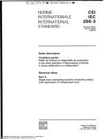
The equipment shall be connected as in Figure 2.
VSWR-bridge
G
EUT
Equipment
under test
Variable signal
generator
Oscilloscope
IEC 2502/10
Figure 2 – Measurement of return loss
4.2.1.4
Measurement procedure
All coaxial input and output ports, other than those under test, shall be terminated in 75 Ω.
Ensure that there is no supply voltage on the port being measured as this could damage the
bridge. If it is necessary to use a voltage blocking device, use one with a good return loss
(10 dB above requirement).
Only good quality calibrated connectors, adaptors and cables shall be used.
The measurement procedure comprises the following steps:
a) connect the equipment as shown in Figure 2;
b) set the signal generator output level so that the equipment under test is not overloaded;
c) use calibrated mismatches to calibrate the display on the oscilloscope;
d) connect the equipment under test as shown in Figure 2 and check the return loss over the
specified frequency range.
4.2.2
Flatness
Methods of measurement are well-known and a full description of the procedure is not necessary.
Measurement is commonly made with a 75 Ω scalar or vector network analyzer. Care shall be
taken that all equipment used (connectors, adaptors, cable, etc.) are well-matched.
4.2.3
Chrominance/luminance delay inequality for PAL/SECAM only
The well-known 20T pulse method of measurement is used as described in IEC 60728-5.
Copyrighted material licensed to BR Demo by Thomson Reuters (Scientific), Inc., subscriptions.techstreet.com, downloaded on Nov-28-2014 by James Madison. No further reproduction or distribution is permitted. Uncontrolled when printe
60728-3 IEC:2010
4.3
60728-3 IEC:2010
Non-linear distortion
4.3.1
General
In a non-linear device, the expression for the output signal will, in general, have an infinity of
terms, each generated from one or more of the (assumed sinusoidal) terms in the input, and
particularly by the interaction of two or more terms. A detailed derivation is described in the
Annex A.
A method of measurement of non-linearity for pure digital channel load is under consideration.
4.3.2
Types of measurements
Measurements related to the following phenomena are described:
•
intermodulation between two or three single frequency signals;
•
composite beats produced by a number of single frequency signals;
•
composite crossmodulation between a number of single frequency signals.
A proper specification shall include at least the following details:
a) the particular effect that is measured;
b) the required signal to distortion ratio.
The result of the measurement shall be given as the worst-case maximum signal level at the
equipment output that allows the required signal to distortion ratio to be met. If the output level is sloped with frequency, this shall be defined.
The effect shall be defined as being of a particular order (e.g. "third-order intermodulation").
4.3.3
4.3.3.1
Intermodulation
General
The two equal carrier and the three equal carrier methods described are applicable to the
measurement of the ratio of the carrier to a single intermodulation product at a specified point
within the cable network. The methods can also be used to determine the intermodulation performance of individual items of equipment.
NOTE 1 It should be especially noted that the simultaneous use of many channels spaced by the same frequency
interval results in a large number of intermodulation products (particularly those of the third-order) falling near the
vision carrier of a wanted television channel.
In these cases, the resultant interference is of an extremely complex nature and an alternative
measurement procedure will be needed. This is covered in 4.3.4 and 4.3.5.
Examples of second-order and third-order intermodulation products are given in Annex B.
Second-order products are encountered only in wideband equipment and systems, covering
more than one octave, and shall be measured using two signals (see Clause B.1).
Third-order products are encountered in wideband and narrowband equipment and systems
and shall be measured using three signals (see Clause B.2).
NOTE 2 If the unequal carrier method of measurement, as described in IEC 60728-5, is used, the output level giving the appropriate signal to distortion ratio must be decreased by 6 dB to obtain the correct result for the equal
carrier method described here.
Copyrighted material licensed to BR Demo by Thomson Reuters (Scientific), Inc., subscriptions.techstreet.com, downloaded on Nov-28-2014 by James Madison. No further reproduction or distribution is permitted. Uncontrolled when printe
– 20 –
4.3.3.2
– 21 –
Equipment required
The following equipment is required.
a) A selective voltmeter covering the frequency range of the equipment or system to be tested. This may be a spectrum analyzer.
b) The appropriate number of signal generators covering the frequencies at which the tests
are to be carried out.
c) A variable attenuator with a range greater than the signal to intermodulation ratio expected, if not incorporated in the voltmeter described in 4.3.3.2 a).
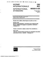
d) A combiner will be required for tests on equipment and systems with a single input
(Figure 3).
NOTE Additional items may be necessary, for example to ensure that the measurements are not affected by spurious signals generated in the test equipment itself (Annex C).
4.3.3.3
Connection of equipment
The equipment shall be connected as shown in Figure 3.
Signal
generators
LP-filters
G
Selective
voltmeter
Combiner
G
Σ
EUT
A
V
G
G
Pilot generator if
required for AGC
IEC 2503/10
NOTE 1 The requirement for the items of test equipment indicated by dotted lines depends on the results of
checks given in Annex C. The filters at the signal generator outputs may be needed to suppress spurious signals.
The selective voltmeter input filter may be required to prevent intermodulation in the meter. If a filter is used, then
the possible mismatch should be avoided by not reducing the attenuator value below 10 dB.
NOTE 2 To avoid intermodulation between the signal generators, it may be necessary for the combiner to be in
the form of one or more directional couplers (see Annex C).
Figure 3 – Basic arrangement of test equipment for evaluation
of the ratio of signal to intermodulation product
4.3.3.4
Measurement procedure
The measurement procedure comprises the following steps.
a) General
Unless otherwise required, the reference output levels used in the measurements shall be the
nominal output levels for the equipment. It shall be quoted whether the signal output levels
are constant over the frequency range or not. If the specified output levels are not constant
over frequency range then the output levels off all the test signals shall be quoted in the results.
Copyrighted material licensed to BR Demo by Thomson Reuters (Scientific), Inc., subscriptions.techstreet.com, downloaded on Nov-28-2014 by James Madison. No further reproduction or distribution is permitted. Uncontrolled when printe
60728-3 IEC:2010
60728-3 IEC:2010
Measurements of both second order and third order products shall be carried out with the test
signals widely and closely spaced over each band of interest at frequencies capable of producing significant products within the overall frequency range.
Where the equipment to be measured includes automatic gain control, tests shall be carried
out at the nominal operating signal input levels.
b) Calibration and checks
A check shall be made to determine if the harmonics and other spurious signals at the outputs
of the signal generators are likely to affect materially the results of the measurements (see
Annex C).
The selective voltmeter shall be calibrated and checked for satisfactory operation (see Annex C).
A check shall be made for possible intermodulation between the signal generators at the output levels to be used for the tests (see Annex C).
c) Measurement
Set the signal generators, in CW mode, to the frequencies of the test signals (see 4.3.3.4 a)
and Annex B) and adjust their outputs and that of the different points of the system as far as
the point of measurement to obtain the specified system operating levels throughout.
Connect the variable attenuator and selective voltmeter and other items if required (see Annex C) to the output of the equipment under test. Tune the meter to each test signal and note
the attenuator value a 1 required to obtain a convenient meter reading R for the reference signal. The attenuator value a 1 should be slightly greater than the signal to intermodulation ratio
expected at the point of measurement.
Tune the meter to the intermodulation product to be measured and reduce the setting of the
variable attenuator to the value a 2 required to obtain the same meter reading R.
NOTE W hen measuring levels of intermodulation products, it may be necessary to insert a filter at the input to the
meter (see Annex C). In such instances the insertion loss (in dB) of the filter at the frequency of the products shall
be added to the attenuator value.
The signal to intermodulation product ratio in dB is given by
S/I = a 1 – a 2
where
a1
is the attenuator value for the test signal used as a reference in dB;
a2
is the attenuator value for the intermodulation product in dB.
4.3.4
4.3.4.1
Composite triple beat
General
The method of measurement of composite triple beat using CW signals is applicable to the
measurement of the ratio of the carrier to composite triple beat at a specified point in a cable
network. The method can also be used to determine the composite triple beat intermodulation
performance of individual items of equipment.
When the input signals are at regularly spaced intervals (as is common in most allocations for
TV channels), the various distortion products tend to cluster in groups, close to the TV channels. The number of different products in each cluster increases rapidly with the number of
Copyrighted material licensed to BR Demo by Thomson Reuters (Scientific), Inc., subscriptions.techstreet.com, downloaded on Nov-28-2014 by James Madison. No further reproduction or distribution is permitted. Uncontrolled when printe
– 22 –
– 23 –
channels, and they combine in different ways, depending on the degree of coherence between
generating signals, and the relative phases of the different distortion products.
The method described in this subclause measures the non-linear distortion of a device or system by the composite effect of all the beats clustered within ±15 kHz of the vision carrier of a
TV channel. During the measurement, the vision carrier of that channel shall be turned off, so
that the composite triple beat measured is that generated by all the carriers except that of the
measured channel.
The method is used to support a specification of the following general format:
"The composite triple beat ratio for groups of carriers in channel (A) at (B) dB(µV) is (C) dB."
where
(A) designates the channel in which the test is made. If omitted, the specification is understood to be a minimum specification for measurements at all the channels specified by the
list of carriers;
(B) is the reference level at which all the carriers should be set during the measurement, unless otherwise specified. If all the carriers are not at the same level, the specification
should clearly indicate the level of each carrier relative to the reference level;
(C) is the composite triple beat ratio, usually given as a minimum specification.
Because of the large variety of frequency plans in use throughout the world and the need to
compare readily performance specifications of different manufacturer's equipment, the measurement should be made with the carriers listed in Annex D (the carriers are all in an 8 MHz
raster, except for the special case of 48,25 MHz).
The vision carrier frequencies are arranged in groups and only complete groups shall be
used, except as stated below. If an amplifier is specified up to 450 MHz, group A shall be
used. If specified up to 550 MHz, groups A and B shall be used. If specified up to 862 MHz,
all groups A, B, C, D and E shall be used.
If an amplifier is specified up to 1 000 MHz the method of measurement for pure digital channel load should be used. This method of measurement is currently under consideration.
Group A can also be used in part, dependent on the specified bandwidth of the equipment under test. The frequencies deleted shall be stated. If the carrier 48,25 MHz is not used in case
where the forward path starts with 85 MHz, then the results of measurements shall be published including the notice "without Band I". If the equipment can operate at all frequencies in
group A this result shall be quoted together with the result where only a part of group A is
used.
For all pass bands, the performance shall be quoted for the maximum possible number of
complete groups. The manufacturer may, in addition, provide a performance figure for a larger
number of carriers. The frequencies deleted shall be stated.
4.3.4.2
Equipment required
The following equipment is required:
a) a spectrum analyzer with 30 kHz intermediate frequency (IF) bandwidth and 10 Hz video
bandwidth capability;
NOTE W hen using a spectrum analyzer with minimum video filtering capabilities greater than 10 Hz, the
composite third-order distortion may be noisy and should be read at the middle of the trace.
b) a variable 75 Ω attenuator, adjustable in 1 dB steps;
Copyrighted material licensed to BR Demo by Thomson Reuters (Scientific), Inc., subscriptions.techstreet.com, downloaded on Nov-28-2014 by James Madison. No further reproduction or distribution is permitted. Uncontrolled when printe
60728-3 IEC:2010