Iec 60747 14 4 2011
Bạn đang xem bản rút gọn của tài liệu. Xem và tải ngay bản đầy đủ của tài liệu tại đây (1.53 MB, 202 trang )
®
Edition 1.0 2011-01
INTERNATIONAL
STANDARD
NORME
INTERNATIONALE
Semiconductor devices – Discrete devices –
Part 14-4: Semiconductor accelerometers
IEC 60747-14-4:2011
Dispositifs à semiconducteurs – Dispositifs discrets –
Partie 14-4: Accéléromètres à semiconducteurs
colour
inside
Copyrighted material licensed to BR Demo by Thomson Reuters (Scientific), Inc., subscriptions.techstreet.com, downloaded on Nov-28-2014 by James Madison. No further reproduction or distribution is permitted. Uncontrolled when printe
IEC 60747-14-4
All rights reserved. Unless otherwise specified, no part of this publication may be reproduced or utilized in any form or by
any means, electronic or mechanical, including photocopying and microfilm, without permission in writing from either IEC or
IEC's member National Committee in the country of the requester.
If you have any questions about IEC copyright or have an enquiry about obtaining additional rights to this publication,
please contact the address below or your local IEC member National Committee for further information.
Droits de reproduction réservés. Sauf indication contraire, aucune partie de cette publication ne peut être reproduite
ni utilisée sous quelque forme que ce soit et par aucun procédé, électronique ou mécanique, y compris la photocopie
et les microfilms, sans l'accord écrit de la CEI ou du Comité national de la CEI du pays du demandeur.
Si vous avez des questions sur le copyright de la CEI ou si vous désirez obtenir des droits supplémentaires sur cette
publication, utilisez les coordonnées ci-après ou contactez le Comité national de la CEI de votre pays de résidence.
IEC Central Office
3, rue de Varembé
CH-1211 Geneva 20
Switzerland
Email:
Web: www.iec.ch
About the IEC
The International Electrotechnical Commission (IEC) is the leading global organization that prepares and publishes
International Standards for all electrical, electronic and related technologies.
About IEC publications
The technical content of IEC publications is kept under constant review by the IEC. Please make sure that you have the
latest edition, a corrigenda or an amendment might have been published.
Catalogue of IEC publications: www.iec.ch/searchpub
The IEC on-line Catalogue enables you to search by a variety of criteria (reference number, text, technical committee,…).
It also gives information on projects, withdrawn and replaced publications.
IEC Just Published: www.iec.ch/online_news/justpub
Stay up to date on all new IEC publications. Just Published details twice a month all new publications released. Available
on-line and also by email.
Electropedia: www.electropedia.org
The world's leading online dictionary of electronic and electrical terms containing more than 20 000 terms and definitions
in English and French, with equivalent terms in additional languages. Also known as the International Electrotechnical
Vocabulary online.
Customer Service Centre: www.iec.ch/webstore/custserv
If you wish to give us your feedback on this publication or need further assistance, please visit the Customer Service
Centre FAQ or contact us:
Email:
Tel.: +41 22 919 02 11
Fax: +41 22 919 03 00
A propos de la CEI
La Commission Electrotechnique Internationale (CEI) est la première organisation mondiale qui élabore et publie des
normes internationales pour tout ce qui a trait à l'électricité, à l'électronique et aux technologies apparentées.
A propos des publications CEI
Le contenu technique des publications de la CEI est constamment revu. Veuillez vous assurer que vous possédez
l’édition la plus récente, un corrigendum ou amendement peut avoir été publié.
Catalogue des publications de la CEI: www.iec.ch/searchpub/cur_fut-f.htm
Le Catalogue en-ligne de la CEI vous permet d’effectuer des recherches en utilisant différents critères (numéro de référence,
texte, comité d’études,…). Il donne aussi des informations sur les projets et les publications retirées ou remplacées.
Just Published CEI: www.iec.ch/online_news/justpub
Restez informé sur les nouvelles publications de la CEI. Just Published détaille deux fois par mois les nouvelles
publications parues. Disponible en-ligne et aussi par email.
Electropedia: www.electropedia.org
Le premier dictionnaire en ligne au monde de termes électroniques et électriques. Il contient plus de 20 000 termes et
dộfinitions en anglais et en franỗais, ainsi que les termes équivalents dans les langues additionnelles. Egalement appelé
Vocabulaire Electrotechnique International en ligne.
Service Clients: www.iec.ch/webstore/custserv/custserv_entry-f.htm
Si vous désirez nous donner des commentaires sur cette publication ou si vous avez des questions, visitez le FAQ du
Service clients ou contactez-nous:
Email:
Tél.: +41 22 919 02 11
Fax: +41 22 919 03 00
Copyrighted material licensed to BR Demo by Thomson Reuters (Scientific), Inc., subscriptions.techstreet.com, downloaded on Nov-28-2014 by James Madison. No further reproduction or distribution is permitted. Uncontrolled when printe
THIS PUBLICATION IS COPYRIGHT PROTECTED
Copyright © 2011 IEC, Geneva, Switzerland
®
Edition 1.0 2011-01
INTERNATIONAL
STANDARD
NORME
INTERNATIONALE
colour
inside
Semiconductor devices – Discrete devices –
Part 14-4: Semiconductor accelerometers
Dispositifs à semiconducteurs – Dispositifs discrets –
Partie 14-4: Accéléromètres à semiconducteurs
INTERNATIONAL
ELECTROTECHNICAL
COMMISSION
COMMISSION
ELECTROTECHNIQUE
INTERNATIONALE
PRICE CODE
CODE PRIX
ICS 31.080.01
® Registered trademark of the International Electrotechnical Commission
Marque déposée de la Commission Electrotechnique Internationale
XD
ISBN 978-2-88912-323-0
Copyrighted material licensed to BR Demo by Thomson Reuters (Scientific), Inc., subscriptions.techstreet.com, downloaded on Nov-28-2014 by James Madison. No further reproduction or distribution is permitted. Uncontrolled when printe
IEC 60747-14-4
60747-14-4 IEC:2011
CONTENTS
FOREWORD ........................................................................................................................... 5
INTRODUCTION ..................................................................................................................... 7
1
Scope ............................................................................................................................... 8
2
Normative references ....................................................................................................... 8
3
Terminology and letter symbols ........................................................................................ 9
4
3.1 Terms and definitions .............................................................................................. 9
3.2 Letter symbols ....................................................................................................... 15
Essential ratings and characteristics ............................................................................... 16
4.1
5
General ................................................................................................................. 16
4.1.1 Operating principle .................................................................................... 16
4.1.2 Single axis and multi-axis .......................................................................... 16
4.1.3 Performance evaluation ............................................................................. 17
4.1.4 Sensitivity .................................................................................................. 17
4.1.5 Classification ............................................................................................. 18
4.1.6 Symbol (g) ................................................................................................. 19
4.1.7 Customer and supplier ............................................................................... 19
4.1.8 Linearity and nonlinearity ........................................................................... 19
4.1.9 Element materials ...................................................................................... 19
4.1.10 Handling precautions ................................................................................. 20
4.1.11 Accelerometer mounting condition ............................................................. 20
4.1.12 Specifications ............................................................................................ 20
4.2 Ratings (limiting values) ........................................................................................ 20
4.3 Recommended operating conditions ...................................................................... 20
4.4 Characteristics ...................................................................................................... 21
4.4.1 Measurement range ................................................................................... 21
4.4.2 Sensitivity and sensitivity error .................................................................. 21
4.4.3 Bias (offset) and bias (offset) error ............................................................ 21
4.4.4 Linearity .................................................................................................... 21
4.4.5 Misalignment ............................................................................................. 22
4.4.6 Cross-axis sensitivity ................................................................................. 22
4.4.7 Cross-coupling coefficient.......................................................................... 22
4.4.8 Temperature coefficient of sensitivity ......................................................... 22
4.4.9 Temperature coefficient of bias.................................................................. 22
4.4.10 Frequency response .................................................................................. 22
4.4.11 Supply current ........................................................................................... 22
4.4.12 Output noise .............................................................................................. 22
4.4.13 Ratiometricity ............................................................................................ 22
4.4.14 Self test ..................................................................................................... 23
Measuring methods ........................................................................................................ 23
5.1
5.2
General ................................................................................................................. 23
5.1.1 Standard test conditions ............................................................................ 23
5.1.2 Applicable measurement methods for test and calibration method ............. 23
Testing methods for characteristics ....................................................................... 25
5.2.1 Measurement range ................................................................................... 25
5.2.2 Supply voltage range ................................................................................. 26
5.2.3 Sensitivity and sensitivity error .................................................................. 26
Copyrighted material licensed to BR Demo by Thomson Reuters (Scientific), Inc., subscriptions.techstreet.com, downloaded on Nov-28-2014 by James Madison. No further reproduction or distribution is permitted. Uncontrolled when printe
–2–
6
–3–
5.2.4 Bias and bias error .................................................................................... 26
5.2.5 Linearity .................................................................................................... 27
5.2.6 Misalignment ............................................................................................. 29
5.2.7 Cross-axis sensitivity ................................................................................. 30
5.2.8 Cross-coupling coefficient.......................................................................... 30
5.2.9 Temperature coefficient of sensitivity ......................................................... 31
5.2.10 Temperature coefficient of bias.................................................................. 31
5.2.11 Frequency response .................................................................................. 31
5.2.12 Supply current ........................................................................................... 35
5.2.13 Output noise .............................................................................................. 35
Acceptance and reliability ............................................................................................... 36
6.1
Environmental test ................................................................................................ 36
6.1.1 High temperature storage .......................................................................... 36
6.1.2 Low-temperature storage ........................................................................... 36
6.1.3 Temperature humidity storage ................................................................... 37
6.1.4 Temperature cycle ..................................................................................... 37
6.1.5 Thermal shock ........................................................................................... 37
6.1.6 Salt mist .................................................................................................... 37
6.1.7 Vibration .................................................................................................... 37
6.1.8 Mechanical shock ...................................................................................... 37
6.1.9 Electrical noise immunity ........................................................................... 37
6.1.10 Electro-static discharge immunity .............................................................. 37
6.1.11 Electro-magnetic field radiation immunity ................................................... 38
6.2 Reliability test........................................................................................................ 38
6.2.1 Steady-state life ........................................................................................ 38
6.2.2 Temperature humidity life .......................................................................... 38
Annex A (informative) Definition of sensitivity matrix of an accelerometer ............................ 39
Annex B (informative) Dynamic linearity measurement using an impact acceleration
generator .............................................................................................................................. 79
Annex C (informative) Measurement of peak sensitivity ....................................................... 88
Bibliography .......................................................................................................................... 97
Figure 1 – Single axis accelerometer .................................................................................... 17
Figure 2 – Multi-axis accelerometer ...................................................................................... 17
Figure 3 – Concept of the mathematical definition of accelerometers .................................... 18
Figure 4 – Concept of dynamic linearity of an accelerometer on gain .................................... 28
Figure 5 – Concept of dynamic linearity of an accelerometer on phase ................................. 29
Figure 6 – The semiconductor accelerometer as a system .................................................... 33
Figure 7 – Example of the structure of assembled semiconductor accelerometer
system for the concept of accelerometer frequency response ............................................... 34
Figure 8 – Schematic diagram of frequency response measurement by electrical input ......... 35
Figure A.1 – Example of direction cosine .............................................................................. 46
Figure A.2 – Accelerometers or pick-offs assembled in a normal co-ordinate system
(top figure) and the acceleration component projection to the three co-ordinate axis
plains, XY, YZ and ZX (bottom figure) ................................................................................... 53
Figure B.1 – Set-up for dynamic linearity measurement ........................................................ 86
Figure C.1 – Peak sensitivity as a function of each frequency bandwidth from DC to f n ......... 88
Figure C.2 – Set-up for the control of frequency bandwidth of shock acceleration ................. 96
Copyrighted material licensed to BR Demo by Thomson Reuters (Scientific), Inc., subscriptions.techstreet.com, downloaded on Nov-28-2014 by James Madison. No further reproduction or distribution is permitted. Uncontrolled when printe
60747-14-4 IEC:2011
60747-14-4 IEC:2011
Table 1 – List of letter symbols ............................................................................................. 15
Table 2 – Level of accelerometers and the definition ............................................................. 18
Table 3 – Test items and the recommended corresponding measurement methods .............. 24
Table 4 – Relation between recommended applicable calibration methods and type of
accelerometers ..................................................................................................................... 25
Table A.1 – Symbols for the relationship between input acceleration and the output
signal from an accelerometer using one-dimensional vibration table ..................................... 46
Table A.2 – Symbols for input acceleration and output signals from an accelerometer .......... 47
Table A.3 – Definition of symbols for describing the input acceleration, output signal
from the target accelerometer and the direction cosine repeated three times ........................ 47
Table A.4 – Relationship between the expression of transfer function in a matrix form
and the number of axis of the target accelerometers ............................................................. 49
Table A.5 – Definition of vector space related to the generalization of the transverse
sensitivity using the vector space concept ............................................................................ 57
Table A.6 – Relation between input acceleration and output signal for the calibration,
using the six-dimensional vibration table ............................................................................... 59
Table A.7 – Normal sensitivities, explicit cross-sensitivities and implicit crosssensitivities obtained by the calibration carried out in the application acceleration
vector space with three dimensions ...................................................................................... 75
Table A.8 – Normal sensitivities, explicit cross-sensitivities and implicit crosssensitivities obtained by the calibration carried out in the application acceleration
vector space with six dimensions .......................................................................................... 76
Table A.9 – List of symbols in terms of measurement uncertainty using an
accelerometer with M output axis assuming that N is larger than M ....................................... 77
Table B.1 – Dynamic linearity when both input and output are vector quantities .................... 79
Table B.2 – Relations between the direction cosine of the input acceleration to oneaxis accelerometers and the signal from the output axis ....................................................... 80
Table B.3 – Relationship between the direction cosine of the input acceleration to oneaxis accelerometers and the signal from the output axis ....................................................... 81
Table B.4 – Conditions on the direction cosine for dynamic linearity measurement ............... 82
Table B.5 – Relations between the direction cosine of the input acceleration to twoaxis accelerometers and the signal from the output axis ....................................................... 82
Table B.6 – Relations between the direction cosine of the input acceleration to twoaxis accelerometers and the signal from the output axis ....................................................... 83
Table B.7 – Conditions on the direction cosine for the dynamic linearity measurement ......... 83
Table B.8 – Relationship between the direction cosine of the input acceleration to
three-axis accelerometers and the signal from the output axis .............................................. 84
Table B.9 – Relations between the direction cosine of the input acceleration to threeaxis accelerometers and the signal from the output axis ....................................................... 85
Table B.10 – Conditions on the direction cosine for dynamic linearity measurement ............. 85
Table C.1 – Definition of elements in one-axis accelerometer peak sensitivity ...................... 88
Table C.2 – Peak sensitivity of one-axis accelerometer ......................................................... 89
Table C.3 – Relationship of direction cosine and the co-ordinate system of the target
accelerometer ....................................................................................................................... 89
Table C.4 – Definition of elements in two-axis accelerometer peak sensitivity ....................... 91
Table C.5 – Definition of elements in three-axis accelerometer peak sensitivity .................... 93
Copyrighted material licensed to BR Demo by Thomson Reuters (Scientific), Inc., subscriptions.techstreet.com, downloaded on Nov-28-2014 by James Madison. No further reproduction or distribution is permitted. Uncontrolled when printe
–4–
–5–
INTERNATIONAL ELECTROTECHNICAL COMMISSION
____________
SEMICONDUCTOR DEVICES –
DISCRETE DEVICES –
Part 14-4: Semiconductor accelerometers
FOREWORD
1) The International Electrotechnical Commission (IEC) is a worldwide organization for standardization comprising
all national electrotechnical committees (IEC National Committees). The object of IEC is to promote
international co-operation on all questions concerning standardization in the electrical and electronic fields. To
this end and in addition to other activities, IEC publishes International Standards, Technical Specifications,
Technical Reports, Publicly Available Specifications (PAS) and Guides (hereafter referred to as “IEC
Publication(s)”). Their preparation is entrusted to technical committees; any IEC National Committee interested
in the subject dealt with may participate in this preparatory work. International, governmental and nongovernmental organizations liaising with the IEC also participate in this preparation. IEC collaborates closely
with the International Organization for Standardization (ISO) in accordance with conditions determined by
agreement between the two organizations.
2) The formal decisions or agreements of IEC on technical matters express, as nearly as possible, an international
consensus of opinion on the relevant subjects since each technical committee has representation from all
interested IEC National Committees.
3) IEC Publications have the form of recommendations for international use and are accepted by IEC National
Committees in that sense. While all reasonable efforts are made to ensure that the technical content of IEC
Publications is accurate, IEC cannot be held responsible for the way in which they are used or for any
misinterpretation by any end user.
4) In order to promote international uniformity, IEC National Committees undertake to apply IEC Publications
transparently to the maximum extent possible in their national and regional publications. Any divergence
between any IEC Publication and the corresponding national or regional publication shall be clearly indicated in
the latter.
5) IEC itself does not provide any attestation of conformity. Independent certification bodies provide conformity
assessment services and, in some areas, access to IEC marks of conformity. IEC is not responsible for any
services carried out by independent certification bodies.
6) All users should ensure that they have the latest edition of this publication.
7) No liability shall attach to IEC or its directors, employees, servants or agents including individual experts and
members of its technical committees and IEC National Committees for any personal injury, property damage or
other damage of any nature whatsoever, whether direct or indirect, or for costs (including legal fees) and
expenses arising out of the publication, use of, or reliance upon, this IEC Publication or any other IEC
Publications.
8) Attention is drawn to the Normative references cited in this publication. Use of the referenced publications is
indispensable for the correct application of this publication.
International Standard IEC 60747-14-4 has been prepared by subcommittee 47E: Discrete
semiconductor devices, of IEC technical committee 47: Semiconductor devices.
This part of IEC 60747 should be read in conjunction with IEC 60747-1:2006. It provides basic
information on semiconductor
–
terminology;
–
letter symbols;
–
essential ratings and characteristics;
–
measuring methods;
–
acceptance and reliability.
Copyrighted material licensed to BR Demo by Thomson Reuters (Scientific), Inc., subscriptions.techstreet.com, downloaded on Nov-28-2014 by James Madison. No further reproduction or distribution is permitted. Uncontrolled when printe
60747-14-4 IEC:2011
60747-14-4 IEC:2011
The text of this standard is based on the following documents:
FDIS
Report on voting
47E/405/FDIS
47E/409/RVD
Full information on the voting for the approval of this standard can be found in the report on
voting indicated in the above table.
This publication has been drafted in accordance with the ISO/IEC Directives, Part 2.
A list of all the parts in the IEC 60747 series, under the general title Semiconductor devices –
Discrete devices, can be found on the IEC website.
Future standards in this series will carry the new general title as cited above. Titles of existing
standards in this series will be updated at the time of the next edition.
The committee has decided that the contents of this publication will remain unchanged until
the stability date indicated on the IEC web site under "" in the data
related to the specific publication. At this date, the publication will be
•
•
•
•
reconfirmed,
withdrawn,
replaced by a revised edition, or
amended.
IMPORTANT – The 'colour inside' logo on the cover page of this publication indicates
that it contains colours which are considered to be useful for the correct
understanding of its contents. Users should therefore print this document using a
colour printer.
Copyrighted material licensed to BR Demo by Thomson Reuters (Scientific), Inc., subscriptions.techstreet.com, downloaded on Nov-28-2014 by James Madison. No further reproduction or distribution is permitted. Uncontrolled when printe
–6–
–7–
INTRODUCTION
The International Electrotechnical Commission (IEC) draws attention to the fact that it is
claimed that compliance with this document may involve the use of a patent concerning
following items.
a) Measurement technique and apparatus for matrix sensitivity in “definition of sensitivity
matrix of an accelerometer” given in Subclause 4.1.5 and Annex A.
b) Measurement technique and apparatus for the dynamic linearity measurement of AC
accelerometers in “dynamic linearity measurement using an impact acceleration
generator” given in Annex B.
c) Measurement technique and apparatus for the frequency response measurement of
accelerometers under the frequency bandwidth control in “method of controlling the
frequency bandwidth of the shock acceleration” given in Clause C.5.
d) Measurement technique and apparatus for the dynamic response and peak sensitivity
measurement of accelerometers in the form of matrix using elastic pulse in “definition of
sensitivity matrix of an accelerometer” given in Annex A.
e) Projectiles for frequency bandwidth control in “method of controlling the frequency
bandwidth of the shock acceleration” given in Clause C.5 and for the dynamic response
and peak sensitivity measurement of accelerometers in the form of matrix using elastic
pulse in “definition of sensitivity matrix of an accelerometer” given in Annex A.
IEC takes no position concerning the evidence, validity and scope of this patent right.
The holder of these patent rights has assured the IEC that he/she is willing to negotiate
licences under reasonable and non-discriminatory terms and conditions with applicants
throughout the world. In this respect, the statement of the holder of this patent right is
registered with IEC. Information may be obtained from:
Name: Intellectual Planning Office, Intellectual Property Department, National Institute of
Advanced Industrial Science and Technology
Address: 1-1-1, Umezono, Tsukuba-shi, Ibaraki, 305-8564, Japan.
Name: VectorDynamics Corporation
Address: 1-11-7 Higashikanda, Chiyoda-ku, Tokyo, 101-0031, Japan.
Heights Kanda Iwamotocho #305
Attention is drawn to the possibility that some of the elements of this document may be the
subject of patent rights other than those identified above. IEC shall not be held responsible for
identifying any or all such patent rights.
ISO (www.iso.org/patents) and IEC ( maintain online data bases of patents relevant to their standards. Users are encouraged to consult the
data bases for the most up to date information concerning patents.
Copyrighted material licensed to BR Demo by Thomson Reuters (Scientific), Inc., subscriptions.techstreet.com, downloaded on Nov-28-2014 by James Madison. No further reproduction or distribution is permitted. Uncontrolled when printe
60747-14-4 IEC:2011
60747-14-4 IEC:2011
SEMICONDUCTOR DEVICES –
DISCRETE DEVICES –
Part 14-4: Semiconductor accelerometers
1
Scope
This part of IEC 60747 applies to semiconductor accelerometers for all types of products.
This standard applies not only to typical semiconductor accelerometers with built-in electric
circuits, but also to semiconductor accelerometers accompanied by external circuits.
This standard does not (or should not) violate (or interfere with) the agreement between
customers and suppliers in terms of a new model or parameters for business.
NOTE 1 This standard, although directed toward semiconductor accelerometers, may be applied in whole or in
part to any mass produced type of accelerometer.
NOTE 2 The purpose of this standard is to allow for a systematic description, which covers the subjects initiated
by the advent of semiconductor accelerometers. The tasks imposed on the semiconductor accelerometers are not
only common to all accelerometers but also inherent to them and not yet totally solved. The descriptions are based
on latest research results. One typical example is the multi-axis accelerometer. This standard states the method of
measuring acceleration as a vector quantity using multi-axis accelerometers.
NOTE 3 This standard does not conflict in any way with any existing parts of either ISO 16063 or ISO 5347. This
standard intends to provide the concepts and the procedures of calibration of the semiconductor multi-axis
accelerometers which are used not only for the measurement of acceleration but also for the control of motion in
the wide frequencies ranging from DC.
2
Normative references
The following referenced documents are indispensable for the application of this document.
For dated references, only the edition cited applies. For undated references, the latest edition
of the referenced document (including any amendments) applies.
IEC 60747-1:2006, Semiconductor devices – Part 1:General
IEC 60749 (all parts), Semiconductor devices – Mechanical and climate test methods
IEC 60749-1, Semiconductor devices – Mechanical and climate test methods – Part 1:
General
IEC 60749-5, Semiconductor devices – Mechanical and climatic test methods – Part 5:
Steady-state temperature humidity bias life test
IEC 60749-6, Semiconductor devices – Mechanical and climatic test methods – Part 6:
Storage at high temperature
IEC 60749-10, Semiconductor devices – Mechanical and climatic test methods – Part 10:
Mechanical shock
IEC 60749-11, Semiconductor devices – Mechanical and climatic test methods – Part 11:
Rapid change of temperature – Two-fluid-bath method
Copyrighted material licensed to BR Demo by Thomson Reuters (Scientific), Inc., subscriptions.techstreet.com, downloaded on Nov-28-2014 by James Madison. No further reproduction or distribution is permitted. Uncontrolled when printe
–8–
–9–
IEC 60749-12, Semiconductor devices – Mechanical and climatic test methods – Part 12:
Vibration, variable frequency
IEC 60749-13, Semiconductor devices – Mechanical and climatic test methods – Part 13: Salt
atmosphere
IEC 60749-25, Semiconductor devices – Mechanical and climatic test methods – Part 25:
Temperature cycling
IEC 61000-4 (all parts), Electromagnetic compatibility (EMC) – Part 4: Testing and
measurement techniques
IEC 61000-4-2:1995, Electromagnetic compatibility (EMC) –
measurement techniques – Electrostatic discharge immunity test
Part
4-2:
Testing
and
IEC 61000-4-3:2006, Electromagnetic compatibility (EMC) – Part 4-3: Testing and
measurement techniques – Radiated, radio-frequency, electromagnetic field immunity test
IEC 61000-4-4:2004, Electromagnetic compatibility (EMC) – Part 4:Testing and measurement
techniques – Section 4: Electrical fast transient/burst immunity test
ISO 5347 (all parts), Methods for the calibration of vibration and shock pick-ups
ISO 5347-11:1993, Methods for the calibration of vibration and shock pick-ups – Part 11:
Testing of transverse vibration sensitivity
ISO/IEC Guide 99, International vocabulary of metrology – Basic and general concepts and
associated terms (VIM)
3
3.1
Terminology and letter symbols
Terms and definitions
For the purpose of this document, the following terms and definitions apply.
3.1.1
accelerometer
device whose output is a vector representing the projection of the acceleration in a
multidimensional space of the acceleration applied to it
3.1.2
AC accelerometer
accelerometer which has a high-pass filter in either real or equivalent signal processing
circuits in characteristics
NOTE It responds to AC band domain input in its frequency characteristics. This type of accelerometer is useful
for measurement of vibration, shock and sway.
3.1.3
DC accelerometer
accelerometer that responds to the input from DC to specified AC band domain in its
frequency characteristics
NOTE It has the second order open-loop system or closed-loop system. This type of accelerometer is useful for
measurement of inclination angle, velocity and displacement by integration of output.
Copyrighted material licensed to BR Demo by Thomson Reuters (Scientific), Inc., subscriptions.techstreet.com, downloaded on Nov-28-2014 by James Madison. No further reproduction or distribution is permitted. Uncontrolled when printe
60747-14-4 IEC:2011
60747-14-4 IEC:2011
3.1.4
semiconductor accelerometer
accelerometer manufactured by the semiconductor technology for at least one acceleration
sensing element
NOTE A typical example might be a combination of a silicon seismic system by micro-machining with sensing
mechanism and an electrical circuit.
3.1.5
one-dimensional accelerometer
accelerometer whose characteristics are measured in the calibration acceleration vector
space with dimension one
3.1.6
two-dimensional accelerometer
accelerometer whose characteristics are measured in the calibration acceleration vector
space with dimension two
3.1.7
three-dimensional accelerometer
accelerometer whose characteristics are measured in the calibration acceleration vector
space with dimension three
3.1.8
four-dimensional accelerometer
accelerometer whose characteristics are measured in the calibration acceleration vector
space with dimension four
3.1.9
five-dimensional accelerometer
accelerometer whose characteristics are measured in the calibration acceleration vector
space with dimension five
3.1.10
six-dimensional accelerometer
accelerometer whose characteristics are measured in the calibration acceleration vector
space with dimension six
3.1.11
level 1 accelerometer
accelerometer with a sensitivity that is not defined in a form of a matrix
NOTE
The sensitivity along the input axis is separated from the cross axis sensitivity.
3.1.12
level 2 accelerometer
accelerometer with sensitivity in the form of a matrix in which all components of the matrix are
constant as a function of frequency and other parameters if necessary
3.1.13
level 3 accelerometer
accelerometer with sensitivity in the form of a matrix in which some of the components are
defined as functions of frequency and other parameters if necessary
3.1.14
level 4 accelerometer
accelerometer with sensitivity in the form of a matrix in which all of the components are
defined as functions of frequency and other parameters if necessary
Copyrighted material licensed to BR Demo by Thomson Reuters (Scientific), Inc., subscriptions.techstreet.com, downloaded on Nov-28-2014 by James Madison. No further reproduction or distribution is permitted. Uncontrolled when printe
– 10 –
– 11 –
3.1.15
input acceleration vector space
real motion vector space where the input acceleration is an element of a set
NOTE Input acceleration vector space is divided into the application acceleration vector space and the calibration
acceleration vector space.
3.1.16
accelerometer output vector space
vector space where the output signal from an accelerometer is an element of a set
3.1.17
gravitational acceleration
acceleration due to gravity
NOTE The symbol g denotes a unit of acceleration equal in magnitude to the value of local gravity and the symbol
g n represents the standard value of g under international agreement, g n =9,80665 m/s 2 .
3.1.18
input axis
axis along or about which the accelerometer output for the applied acceleration indicates a
maximum value
NOTE Neither misalignment nor cross-axis sensitivity compensation is employed. The IA direction only may be
marked on the external package.
3.1.19
input reference axis
direction of an axis that is nominally parallel to the input axis
NOTE
It is defined by the package mounting surfaces or external package markings.
3.1.20
output axis
axis along or about which the output of the accelerometer is measured
NOTE
In some cases, it is referred to as the hinge or flexure axis.
3.1.21
output reference axis
direction of an axis that is nominally parallel to the output axis
NOTE
It is defined by the package mounting surfaces or external package markings.
3.1.22
pendulum axis
axis through the proof mass centre in pendulum accelerometers
NOTE
It is perpendicular to and intersecting the output axis.
3.1.23
pendulum reference axis
direction of an axis that is nominally parallel to the pendulum axis
NOTE
It is defined by the package mounting surfaces or external package markings.
3.1.24
misalignment
angle between an input axis and the corresponding input reference axis that is indicated on
the accelerometer package, when the device is at a 0 g position
Copyrighted material licensed to BR Demo by Thomson Reuters (Scientific), Inc., subscriptions.techstreet.com, downloaded on Nov-28-2014 by James Madison. No further reproduction or distribution is permitted. Uncontrolled when printe
60747-14-4 IEC:2011
60747-14-4 IEC:2011
3.1.25
pick-off
device that indicates the displacement of proof mass generated by input acceleration
3.1.26
proof mass
mass whose inertia produces an acceleration signal
NOTE
Pendulum-mass or translational-mass is generally used.
3.1.27
bias
outputs without any acceleration along the input axis
NOTE It may be represented by the algebraic means between the peak outputs given when acceleration is
applied equally along both directions of the input axis.
3.1.28
bias discrepancy
difference between the bias values at the 1 g and the 0 g positions
NOTE
It is a function of the non-linear characteristics of sensitivity.
3.1.29
bias error
algebraic difference between the bias of a device and the nominal bias in the specification
NOTE
The bias specification of the device is comprised of the variation due to temperature and voltage.
3.1.30
temperature coefficient of bias
change in bias per unit change in temperature relative to the bias at the specified temperature
3.1.31
ratiometricity
proportionality of the output acceleration to the supply voltage change on the accelerometer
3.1.32
supply voltage range
maximum and minimum supply voltage values among which the device can operate normally
3.1.33
measurement range
maximum and minimum acceleration values that are measurable
3.1.34
input acceleration limits
extreme values of the input acceleration, within which the accelerometer can keep the
specified performance
3.1.35
first resonant frequency
lowest frequency at which the ratio of output versus input acceleration takes a peak value
3.1.36
dynamic linearity
linearity that is concerned with the relationship between the transient input signals and output
signals
NOTE
See Annex B.
Copyrighted material licensed to BR Demo by Thomson Reuters (Scientific), Inc., subscriptions.techstreet.com, downloaded on Nov-28-2014 by James Madison. No further reproduction or distribution is permitted. Uncontrolled when printe
– 12 –
– 13 –
3.1.37
sensitivity matrix
matrix that transforms the input acceleration vector space to the output signal vector space
under the assumption that the transformation is linear
NOTE 1 Diagonal terms and non-diagonal terms correspond to normal sensitivities and cross-sensitivities,
respectively.
NOTE 2 Calibration of an accelerometer should be recognized as the process of determining all of the
components of the sensitivity matrix.
NOTE 3 Matrix sensitivity can be used to describe the sensitivity of accelerometers of level 2, 3 and 4. It is used
to place an emphasis on the difference between the conventional sensitivity of the level 1 and level 2, 3 and 4
accelerometers (see 4.1.5: Classification)
3.1.38
peak sensitivity matrix
matrix with the components of peak sensitivity considered along the normal sensitivity axis as
the diagonal terms and the components of peak sensitivity considered along the crosssensitivity axis as the non-diagonal terms
3.1.39
sensitivity
output change per unit change of input acceleration in either static or dynamic state
NOTE 1 Sensitivity in steady state of level 1 accelerometers is generally evaluated as the slope of the straight
line that can be fitted by the least square method applied to input-output data obtained by varying the input within
the measurement range.
NOTE 2
Sensitivity for level 2, 3 and 4 accelerometers is expressed by a matrix.
3.1.40
sensitivity error
algebraic difference between a sensitivity of a device and the nominal sensitivity in the
specification, with the percentage expression applied with the nominal sensitivity
NOTE The sensitivity of the device possesses the maximum and the minimum values among the over-all figures
containing the temperature coefficient, etc.
3.1.41
temperature coefficient of sensitivity
change in sensitivity per unit change in temperature relative to the sensitivity at the specified
temperature
3.1.42
normal sensitivity
sensitivity defined along the axis with the maximum sensitivity of an accelerometer
3.1.43
cross-sensitivity
sensitivity defined by the output along the specified axis perpendicular to the input along the
normal sensitivity axis
3.1.44
cross-axis sensitivity
maximum sensitivity in the plane perpendicular to the measuring direction relative to the
sensitivity in the measuring direction
NOTE 1 The maximum sensitivity in the perpendicular plane is obtained as the geometric sum of the sensitivities
in two perpendicular directions in this plane.
NOTE 2
Transverse sensitivity can be used in stead of cross-axis sensitivity.
Copyrighted material licensed to BR Demo by Thomson Reuters (Scientific), Inc., subscriptions.techstreet.com, downloaded on Nov-28-2014 by James Madison. No further reproduction or distribution is permitted. Uncontrolled when printe
60747-14-4 IEC:2011
60747-14-4 IEC:2011
3.1.45
cross-coupling coefficient
ratio of the variation of accelerometer output to the product of acceleration applied normal
and parallel to an input reference axis
3.1.46
peak sensitivity
value as the ratio of the maximum output signal divided by the maximum input acceleration
NOTE
See Annex C.
3.1.47
frequency response of sensitivity
ratio of the output signal to the applied acceleration at discrete frequency or in narrow
bandwidth as a function of frequency
3.1.48
frequency response of cross-sensitivity
ratio of the output signal to the applied acceleration at discrete frequency or in narrow
bandwidth in orthogonal direction as a function of frequency
3.1.49
Doppler shift interferometer
interferometer based on Doppler shift principle
3.1.50
laser interferometer
system that measures a motion by means of an optical interference using a laser as a light
source
NOTE
It serves for the primary calibration of accelerometers.
3.1.51
strain gauge
sensor that electrically detects the strain
3.1.52
uncertainty
parameter, associated with the result of a measurement, that characterizes the dispersion of
the values that could reasonably be attributed to the measurand
NOTE
See Guide to the expression of uncertainty in measurement.
Copyrighted material licensed to BR Demo by Thomson Reuters (Scientific), Inc., subscriptions.techstreet.com, downloaded on Nov-28-2014 by James Madison. No further reproduction or distribution is permitted. Uncontrolled when printe
– 14 –
3.2
– 15 –
Letter symbols
For the purposes of this document, letter symbols given in Table 1, apply.
Table 1 – List of letter symbols
Name and designation
Letter symbol
Remarks
Acceleration:
– at input points of j = 1,···, n
aj
– of a positive specific input to DC accelerometer
a+
– of a negative specific input to DC accelerometer
a−
– of a specific input to AC accelerometer
a rms
– of a positive maximum input
a max
– of a negative maximum input
a min
– due to local gravity
g
– due to standard gravity
gn
Accelerometer output:
– in accelerometer output units
E
– at input-acceleration points of j = 1,···, n
Ej
– at a positive specific input a +
E+
– at a negative specific input a −
E−
– at a specific input arms
– at the UP(+1 g) position
– at the DOWN(–1 g) position
E rms
E up
E down
Bias:
– apparent value
B’
– in the high temperature operating condition
B high
– in the low temperature operating condition
B low
– in the standard condition
B std
– at the 0 g position (0 g bias)
– at the 1 g position (1 g bias)
– temperature coefficient
Bias discrepancy
B0
B1
B tco
Bd
Deviation of the accelerometer output:
– from the straight line at points of E j
– largest absolute value from the straight line
δE j
δE
Linearity
– for static linearity
SL
Cross-coupling coefficient
– for IRA and PA
– for IRA and OA
Kp
Ko
Misalignment of the IA with respect to the IRA:
– composite value
γ
– about the OA
γo
– about the PA
γp
Sensitivity:
– nominal value
S
– apparent value
S’
– in the high temperature operating condition
S high
– in the low temperature operating condition
S low
– in the standard condition
S std
– temperature coefficient
S tco
g n = 9,806 65 m/s 2
Copyrighted material licensed to BR Demo by Thomson Reuters (Scientific), Inc., subscriptions.techstreet.com, downloaded on Nov-28-2014 by James Madison. No further reproduction or distribution is permitted. Uncontrolled when printe
60747-14-4 IEC:2011
60747-14-4 IEC:2011
Table 1 (continued)
Name and designation
Letter symbol
Remarks
Temperature:
– in the high temperature operating condition
T high
– in the low temperature operating condition
T low
– in the standard condition
T std
– minimum value rated during the specified storage time
4
T stg
min
Essential ratings and characteristics
4.1
4.1.1
General
Operating principle
The operating principle of semiconductor accelerometers is almost equal to that of other types
of accelerometers. Accelerometers with heat convection as the operating principle might be
considered an exception. Semiconductor accelerometers can be classified as piezo-resistive
type, and capacitive type, etc. by considering the detection principle of seismic mass motion.
The large variety seen in semiconductor accelerometers is due to the nature of the operating
principles.
NOTE Capacitive type accelerometers include those having driving mechanism such as comb drive accelerometers, servo accelerometers and vibration beam accelerometers, etc.
4.1.2
Single axis and multi-axis
There exist both single-axis type and multi-axis type semiconductor accelerometers. Most of
the technical aspects on the one-axis semiconductor accelerometers are covered by
traditional standards on the subject. Since traditional acceleration devices were invented, the
greatest innovation caused by semiconductor technology is the multi-axis accelerometers up
to the six-axis. This standard is written based on the philosophy that not only single-axis
accelerometers but also multi-axis accelerometers may be described within the same concept.
The idea is simply that the acceleration is a vector quantity. The description given of one-axis
accelerometers in this standard mainly comes from this idea, leading to the generation of
differences from existing standards on accelerometers.
In these cases, each input axis (IA) for accelerometer mount surface should be defined in the
co-ordinate system affixed to the specified accelerometer. The widely accepted idea that
multi-axis accelerometers can measure acceleration as a vector has been re-examined, and
mathematically investigated using a vector space theory. Both the theories and the practical
techniques based on this concept are described in Annexes A to C.
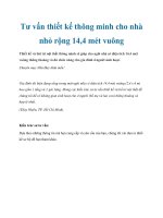
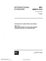
The following figures 1 and 2 show the typical structure of semiconductor accelerometers.
Copyrighted material licensed to BR Demo by Thomson Reuters (Scientific), Inc., subscriptions.techstreet.com, downloaded on Nov-28-2014 by James Madison. No further reproduction or distribution is permitted. Uncontrolled when printe
– 16 –
– 17 –
4
5
1
6
2
7
3
IEC 063/11
Key
1
4
7
flexure hinge
glass
acceleration (Z)
2
5
silicon
pick off electrode
3
6
glass
proof mass
Figure 1 – Single axis accelerometer
4
5
1
6
7
2
8
3
9
IEC 064/11
Key
1
4
7
flexure hinge
glass
acceleration (Z)
2
5
8
Silicon
pick off electrode
acceleration (Y)
3
6
9
glass
proof mass
acceleration (X)
Figure 2 – Multi-axis accelerometer
This standard applies to semiconductor accelerometers with built-in electric circuits. It is not
applicable to the sensing element alone because it does not generate any electric signals.
4.1.3
Performance evaluation
Performance evaluation of accelerometers should be carried out utilizing, in principle, inertia
in local level co-ordinate systems. In some applications, care should be taken over the coordinate system transformation between the local level co-ordinate system and the inertia coordinate system. Local gravity or centripetal acceleration is recommended as the reference
acceleration for measuring the sensitivity of DC accelerometers. To measure the sensitivity of
AC accelerometers and the frequency response characteristics of DC accelerometers, it is
recommended using a vibration generator and a laser interferometer for the primary
calibration.
4.1.4
Sensitivity
The purpose of the accelerometer is to measure acceleration. This can be a definition of
physical function of accelerometers. On the other hand, the definition of mathematical
function of accelerometers is the projection of vector space of actual acceleration vectors to
the output signal vector space, because acceleration is a vector quantity. Therefore, as linear
Copyrighted material licensed to BR Demo by Thomson Reuters (Scientific), Inc., subscriptions.techstreet.com, downloaded on Nov-28-2014 by James Madison. No further reproduction or distribution is permitted. Uncontrolled when printe
60747-14-4 IEC:2011
60747-14-4 IEC:2011
algebra indicates, only a matrix can define the sensitivity of accelerometers, since a matrix
can transform a vector space into another vector space. Figure 3 shows the concept of the
mathematical definition of accelerometers.
1
1
2
3
4
IEC 065/11
Key
1
Dimension
3
Input acceleration vector space
2
Accelerometers
4
Input acceleration vector space
Figure 3 – Concept of the mathematical definition of accelerometers
“Dimension” in Figure 3 stands for the maximum number of linearly independent vectors in the
vector space. Dimension of the space where the accelerometer sensitivity is defined is very
important, because it is related to the size of the sensitivity matrix. The purpose of
acceleration generation using machines for calibration such as vibration tables is to simulate
the application acceleration vector space. Accelerometers shall be calibrated in the calibration
acceleration vector space with the dimension that is normally larger than or equal to the
dimension of the application acceleration vector space.
NOTE 1
For further details see Annex A.
NOTE 2 The concept shown in Figure 3 can be shared with the other vector quantity detection sensors such as
gyros, IMUs, and force sensors.
4.1.5
Classification
It is evident that a matrix should describe the sensitivity of an accelerometer. However, it is
not always practical to obtain the definition of sensitivity using a matrix at every instant,
because it is not always the case that both direction and magnitude are measured. In some
cases, the direction of motion is predictable using a priori information. A typical example
might be the vibration of a beam with a very flat cross-section. On the other hand, the
sensitivity of accelerometers for crash detection should be a matrix, because it is almost
impossible to predict the direction of the crash. In order to cope with these real applications,
this standard introduces the classification of accelerometers, as shown in Table 2.
Table 2 – Level of accelerometers and the definition
Level of accelerometers
Descriptions
Level 4 accelerometer
The sensitivity of level 4 accelerometers is defined as a matrix. All components in
the matrix are defined as functions of frequencies
Level 3 accelerometer
The sensitivity of level 3 accelerometers is defined as a matrix. Some of the
components in the sensitivity matrix are defined as functions of frequency. Nondiagonal components are not zero
Level 2 accelerometer
The sensitivity of level 2 accelerometers is defined as a matrix. All components of
the matrix are constant with a clear frequency and specification including the
nonzero non-diagonal terms
Level 1 accelerometer
The matrix sensitivity is not considered in level 1 accelerometers. The sensitivity
along the input axis is separated from the cross axis sensitivity
Copyrighted material licensed to BR Demo by Thomson Reuters (Scientific), Inc., subscriptions.techstreet.com, downloaded on Nov-28-2014 by James Madison. No further reproduction or distribution is permitted. Uncontrolled when printe
– 18 –
– 19 –
NOTE 1 The ISO 16063 and ISO 5347 series standard might be applicable to level 1 accelerometers. The major
purpose of the descriptions in this standard is to provide the technologies covered by neither the ISO 16063 series
standard nor the ISO 5347 series standard.
NOTE 2 ”Frequency” in Table 1 includes zero frequency, because DC accelerometers for levels 2, 3 and 4
possess matrix sensitivities at 0 Hz.
NOTE 3 All of the components of the static sensitivity matrix for level 2 to level 4 DC accelerometers are defined
at 0 Hz. Each term of the static sensitivity matrix is the same in level 2, level 3 and level 4 accelerometers, i.e. if i
and j of a ij are equal to m and n of a mn of the different level accelerometers, a ij is equal to a mn .
The technical aspects of this classification are as follows:
•
The classification is regarded as the basic framework for accelerometers to meet the
specific application requirement, neither introducing too much nor too little detail.
•
All products fit the above description on the level of accelerometers.
•
The classification should be applied to accelerometers with either angular velocity or
angular acceleration detection capabilities.
•
The classification is applicable to every accelerometer without any regard to the number of
sensitivity axes.
•
The classification clarifies whether the sensitivity is defined in the vector space or not.
•
The classification describes the dimension of the vector space where the sensitivity of the
accelerometer is defined.
•
The classification is beneficial to customers who will recognize it as the fundamental
performance criteria.
NOTE 4
See Annex A for further details.
NOTE 5 ISO/IEC 17025 clearly states that reference standards and calibration guaranteed by NMIs are not the
only way for traceability. It states that the programme for calibration of equipment shall be designed and operated
so as to ensure calibrations and measurements are traceable to the international System of Units (SI) (Système
International d’unités). This standard provides the possibility of establishing the traceability of multi-axis
accelerometers; i.e. calibration based on SI.
NOTE 6
4.1.6
The classification shown in Table 2 is applicable to gyros and IMUs.
Symbol (g)
In this standard, the symbol ‘g’ is used for acceleration when calibration or test is carried out
using local gravity.
4.1.7
Customer and supplier
This standard shall neither violate nor interfere with the agreement between customers and
suppliers in terms of a new model or parameters for business.
4.1.8
Linearity and nonlinearity
In some cases, signals in the non-linear region of an accelerometer are used. This results
from a strong demand for low production cost and special signal processing largely dependent
on the application. In other cases, application requires a simulation model of semiconductor
accelerometers in the system design stage, covering not only linearity but also non-linearity
between input and output.
4.1.9
Element materials
Materials used for semiconductor accelerometers consist mainly of silicon. Ratings of
semiconductor accelerometers depend on the element materials.
Copyrighted material licensed to BR Demo by Thomson Reuters (Scientific), Inc., subscriptions.techstreet.com, downloaded on Nov-28-2014 by James Madison. No further reproduction or distribution is permitted. Uncontrolled when printe
60747-14-4 IEC:2011
4.1.10
60747-14-4 IEC:2011
Handling precautions
Due to the fragile nature of sensing elements and electrical circuits, semiconductor
accelerometers should not be subjected to an environment which exceeds the ratings. This is
in order to avoid permanent changes in the specified characteristics. When handling the
devices, the precautions given in Clause 8 of IEC 60747-1:2006 shall be referred to.
4.1.11
Accelerometer mounting condition
Outer packaging of accelerometers should have enough rigidity for their intended use.
Suppliers should describe the requirements for the accelerometer mounting and mounting
surface conditions in the specifications. Dynamic measurement described in this standard
should be carried out under the recommended conditions.
NOTE A quantitative description concerning sufficient rigidity is described in each calibration measurement
technique.
4.1.12
Specifications
Specifications for semiconductor accelerometers should contain the following:
•
name of manufacturer, model;
•
classification;
•
dimensions, mass (weight) and package type, e.g. DIP;
•
recommended mounting method;
•
ratings, recommended operating conditions and characteristics as defined in 4.2 to 4.4.
4.2
Ratings (limiting values)
The following items should be described in the specification, unless otherwise stated in the
relevant procurement specifications. Stresses over these limits may cause permanent damage
to the devices:
–
storage temperature range;
–
storage humidity range;
–
mechanical shock;
–
supply voltage range;
–
input acceleration limits;
–
maximum supply voltage or current.
4.3
Recommended operating conditions
The following items should be described in the specification, unless otherwise stated in the
relevant procurement specifications. These conditions are recommended in order to keep the
characteristics of the devices stable during operation:
–
operating temperature range;
–
operating humidity range;
– operating acceleration range;
–
nominal supply voltage.
Copyrighted material licensed to BR Demo by Thomson Reuters (Scientific), Inc., subscriptions.techstreet.com, downloaded on Nov-28-2014 by James Madison. No further reproduction or distribution is permitted. Uncontrolled when printe
– 20 –
4.4
– 21 –
Characteristics
4.4.1
General
Characteristics shall be measured at 25 °C, unless otherwise stated. Other temperatures
should be taken from the list in Clause 5 of IEC 60747-1:2006.
4.4.2
Measurement range
Maximum and minimum acceleration values shall be as per the measurable acceleration
values.
4.4.3
Sensitivity and sensitivity error
Sensitivity is defined as output change per unit change of input acceleration. It should be
expressed by output signal (e.g. voltage) per unit input acceleration.
The sensitivity error for level 1 accelerometers is the algebraic difference between the
sensitivity of a device and the nominal sensitivity in the specification, with the percentage
deviation from the nominal sensitivity. Maximum and minimum values among the over-all
figures containing the temperature coefficient etc. should be used.
For level 2, 3 and 4 accelerometers, the sensitivity error is expressed by a matrix. Every
component in the sensitivity error matrix is the algebraic difference between the sensitivity
matrix component and the corresponding nominal sensitivity matrix component in the
specification, with the percentage deviation from the corresponding nominal sensitivity matrix
components.
4.4.4
Bias (offset) and bias (offset) error
Bias is the output without any acceleration along the input axis. This may be represented by
the algebraic means of the two outputs when the acceleration is applied in two directions, +g
and –g, along the input axis and with typical values.
Bias error is the algebraic difference between the bias of a device and the nominal bias in the
specification. Maximum and minimum values among the overall figures containing the
temperature coefficients should be used.
NOTE 1
Offset is also used in a similar way as bias.
NOTE 2
Offset error is also used in a similar way as bias error.
NOTE 3
Bias and bias error are independent from the classification of accelerometers.
4.4.5
4.4.5.1
Linearity
Linearity in DC acceleration measurement
Linearity is defined as the deviation of the output of a device from the straight line defined by
the sensitivity. Percentage expression with the full scale of the specification and maximum
values should be mentioned.
4.4.5.2
Linearity in sinusoidal acceleration measurement
Linearity in sinusoidal acceleration is concerned with both gain and phase. Gain linearity is
defined as the maximum deviation of the gain of a device at each frequency from the straight
line defined by the absolute value of the complex sensitivity in sinusoidal acceleration as a
function of amplitude and frequency of an input signal. Phase linearity is defined as the
maximum deviation of the phase of a device at each frequency from the straight line, defined
by the phase of the complex sensitivity in sinusoidal acceleration, as a function of amplitude
and frequency of an input signal. For details see Annex B.
Copyrighted material licensed to BR Demo by Thomson Reuters (Scientific), Inc., subscriptions.techstreet.com, downloaded on Nov-28-2014 by James Madison. No further reproduction or distribution is permitted. Uncontrolled when printe
60747-14-4 IEC:2011
4.4.6
60747-14-4 IEC:2011
Misalignment
This represents the angle between the input axis and the input reference axis indicated on the
accelerometer package. Maximum values should be specified.
4.4.7
Cross-axis sensitivity
This should be described as the percentage expression of the sensitivity of specified input
axis caused by the acceleration applied along the perpendicular direction to the specified
input axis, with the input axis sensitivity.
NOTE 1
For matrix sensitivity see Annex A.
NOTE 2
This should be described by the non-diagonal terms of sensitivity matrix for level 2 to 4 accelerometers.
4.4.8
Cross-coupling coefficient
This coefficient is observed not only in a pendulum accelerometer with the open-loop control
system but also in the cantilever accelerometer manufactured by micro-machining technology
and is originated from inclination of input axis (e.g. pendulum or cantilever). This is one of the
coefficients by which the deviations of the real output of a device from the straight line defined
by the sensitivity are composed.
This coefficient is calculated by the Equation (8) in 5.2.8 from the data at the specific
positions under the local earth’s gravitation, g. The coefficient should be expressed by the
maximum value.
4.4.9
Temperature coefficient of sensitivity
The maximum per cent change in sensitivity at +25 °C per unit change in temperature.
4.4.10
Temperature coefficient of bias
The maximum per cent change in bias at +25 °C per unit change in temperature.
4.4.11
Frequency response
Frequency response is a set of data or a diagram showing the amplitude ratio and phase shift
between the input that changes sinusoidally over time and the sinusoidal output signal as a
function of frequency. The frequency where the gain decreases to 3 dB below the maximum
gain is called cut-off frequency, f c and the minimum values should be mentioned. It should
be noted that this concept is applicable only to a linear system.
NOTE
4.4.12
For frequency response for level 2 to 4 accelerometers see Annex A.
Supply current
The supply current is specified under the condition of no load and normal temperature, +25 °C,
unless otherwise specified.
4.4.13
Output noise
This comprises the AC components included in the output signal on the steady-state
operation. This should be expressed either as an r.m.s. value in a specified frequency
bandwidth, or as volt per square root of frequency.
4.4.14
Ratiometricity
This represents the linearity of the accelerometer output to the supply voltage change. It
should be clearly stated if capability of ratiometricity exists or not. The output quantity
Copyrighted material licensed to BR Demo by Thomson Reuters (Scientific), Inc., subscriptions.techstreet.com, downloaded on Nov-28-2014 by James Madison. No further reproduction or distribution is permitted. Uncontrolled when printe
– 22 –
– 23 –
variations due to the supply voltage variations may be estimated through this figure, deviation
from the linearity. Ratiometricity is expressed as either the maximum (volts) or percentage.
4.4.15
Self test
This is to check the proper functionality of the accelerometer without any real acceleration.
Functionality is judged by measuring the electrical output when the specified electrical signal
is applied to the specified terminals of the accelerometer. Self test should be specified by
stating the input electrical signal to the self test terminals, the electrical outputs for judgement
and the designated area covered by the self test.
5
Measuring methods
5.1
General
Measurement is divided into two categories:
–
test,
–
calibration.
The difference between test and calibration is made by the traceability to the national
standards. Calibration is the measurement carried out using the instrumentation traceable to
the authorized national standard equipment and techniques written in the specified document.
Uncertainty is indispensable in calibration. Test is more practical than calibration, because it
can be done based on the negotiation between manufacturers and customers without
traceability to national standard. However, it should be noted that the measurement
techniques for calibration could be utilised for test. The basics used for the calibration or test
should be documented, if the corresponding standard does not exist.
5.1.1
Standard test conditions
Standard test conditions are as follows:
a) temperature:
25 °C ± 5 °C
b) relative humidity:
45 % to 75 %, where appropriate
c) air pressure:
86 kPa to 106 kPa, (860 mbar to 1060 mbar)
d) nominal supply voltage
A V ± B V. Supply voltage A and its tolerance B shall be
determined in individual specifications.
The electrical precautions are described in Clause 6 of IEC 60747-1:2006 and the standard
test conditions recommended are in accordance with Clause 5 of IEC 60747-1:2006. The
accelerometer and test equipment shall be brought to the operating condition with the
specified acceleration input. The accelerometer and the immediate environment shall be
allowed to reach thermal equilibrium so that the output of the accelerometer may be stabilized
with the required accuracy before proceeding with the test.
5.1.2
Applicable measurement methods for test and calibration method
The standard temperature condition for calibration is 23 °C ± 3 °C. Relative humidity and air
pressure are the same as shown in 5.1.1. Table 3 shows the relation between a test item and
the recommended corresponding measurement methods. Table 4 shows the relation between
a type of accelerometers and recommended corresponding applicable calibration methods.
Copyrighted material licensed to BR Demo by Thomson Reuters (Scientific), Inc., subscriptions.techstreet.com, downloaded on Nov-28-2014 by James Madison. No further reproduction or distribution is permitted. Uncontrolled when printe
60747-14-4 IEC:2011