Hệ thống common rail hãng NISSAN
Bạn đang xem bản rút gọn của tài liệu. Xem và tải ngay bản đầy đủ của tài liệu tại đây (1.32 MB, 40 trang )
00400013E
Common Rail System for NISSAN
SERVICE MANUAL
Operation
YD1-K2 Type Engine
June, 2003
Diesel Injection Pump
No. E-03-01
For DENSO Authorized
ECD Service Dealer Only
Foreword
To meet the high pressurization requirements for the engine to deliver cleaner exhaust gas emissions, lower fuel
consumption and reduced noise, advanced electronic control technology is being adopted in the fuel injection system.
This manual covers the electronic control model Common Rail system with HP3 pump for the NISSAN YD1-K2 type
engine. Complex theories, special functions and components made by manufacturers other than DENSO are omitted
from this manual.
This manual will help the reader develop an understanding of the basic construction, operation and system configuration
of the DENSO manufactured components and brief diagnostic information.
TABLE OF CONTENTS
1. Product Application . . . . . . . . . . . . . . . . . . . . . . . . . . . . . . . . . . . . . . . . . . . . . . . . . . . . . . . . . . . . . . . . . . . . . . . . . . . . . . . . . . . . 1
1-1. Application . . . . . . . . . . . . . . . . . . . . . . . . . . . . . . . . . . . . . . . . . . . . . . . . . . . . . . . . . . . . . . . . . . . . . . . . . . . . . . . . . . . . . . . 1
1-2. System Components Parts Number . . . . . . . . . . . . . . . . . . . . . . . . . . . . . . . . . . . . . . . . . . . . . . . . . . . . . . . . . . . . . . . . . . . 1
2. Outline . . . . . . . . . . . . . . . . . . . . . . . . . . . . . . . . . . . . . . . . . . . . . . . . . . . . . . . . . . . . . . . . . . . . . . . . . . . . . . . . . . . . . . . . . . . . . . . 2
2-1. Features of System . . . . . . . . . . . . . . . . . . . . . . . . . . . . . . . . . . . . . . . . . . . . . . . . . . . . . . . . . . . . . . . . . . . . . . . . . . . . . . . . 2
2-2. Outline of System . . . . . . . . . . . . . . . . . . . . . . . . . . . . . . . . . . . . . . . . . . . . . . . . . . . . . . . . . . . . . . . . . . . . . . . . . . . . . . . . . . 4
3. Construction and Operation . . . . . . . . . . . . . . . . . . . . . . . . . . . . . . . . . . . . . . . . . . . . . . . . . . . . . . . . . . . . . . . . . . . . . . . . . . . . . 7
3-1. Description of Main Components . . . . . . . . . . . . . . . . . . . . . . . . . . . . . . . . . . . . . . . . . . . . . . . . . . . . . . . . . . . . . . . . . . . . . 7
3-2. Description of Control System Components . . . . . . . . . . . . . . . . . . . . . . . . . . . . . . . . . . . . . . . . . . . . . . . . . . . . . . . . . . 18
3-3. Various Types of Controls . . . . . . . . . . . . . . . . . . . . . . . . . . . . . . . . . . . . . . . . . . . . . . . . . . . . . . . . . . . . . . . . . . . . . . . . . . 22
4. DTC (Diagnosis Trouble Codes) Table . . . . . . . . . . . . . . . . . . . . . . . . . . . . . . . . . . . . . . . . . . . . . . . . . . . . . . . . . . . . . . . . . . . . 27
4-1. About the Codes shown in the table . . . . . . . . . . . . . . . . . . . . . . . . . . . . . . . . . . . . . . . . . . . . . . . . . . . . . . . . . . . . . . . . . 27
4-2. DTC (Diagnosis Trouble Code) Table . . . . . . . . . . . . . . . . . . . . . . . . . . . . . . . . . . . . . . . . . . . . . . . . . . . . . . . . . . . . . . . . . 27
5. External Wiring Diagram . . . . . . . . . . . . . . . . . . . . . . . . . . . . . . . . . . . . . . . . . . . . . . . . . . . . . . . . . . . . . . . . . . . . . . . . . . . . . . . 34
5-1. ECU External Wiring Diagram . . . . . . . . . . . . . . . . . . . . . . . . . . . . . . . . . . . . . . . . . . . . . . . . . . . . . . . . . . . . . . . . . . . . . . . 34
5-2. ECU Connector Diagram . . . . . . . . . . . . . . . . . . . . . . . . . . . . . . . . . . . . . . . . . . . . . . . . . . . . . . . . . . . . . . . . . . . . . . . . . . . 36
-1-
1. Product Application
1-1. Application
1-2. System Components Parts Number
Vehicle Name Vehicle Model Engine Model Exhaust Volume Reference
PREMERA ED YD1-K2 2.2L Made in France
ALMERA HS
TINO HM
Part Name
Applicable Model
DENSO Part
Number
Car Manufacturer
Part Number
Reference
ED
100
HS
100
HS
82
HM
100
HM
82
Supply pump O O O O O 294000-0121 16700 AW401
—
Rail O O O O O 095440-0420 17520 AW400
—
Injector O O
—
O
—
095000-5130 16600 AW400 100kW Engine
——
O
—
O 095000-5180 16600 BN800 82kW Engine
Engine ECU O
————
275800-2193 23710 AW402 Standard
O
————
275800-2203 23710 AW407 w/VDC
O
————
275800-2440 23710 AW410 w/ASCD
O
————
275800-2450 23710 AW415 w/ASCD, VDC
—
O
———
275800-2322 23710 BN811 Standard
—
O
———
275800-2332 23710 BN816 100kW Engine w/VDC
——
O
——
275800-2340 23710 BN800 82kW Engine
——
O
——
275800-2350 23710 BN805 82kW Engine w/VDC
———
O
—
275800-2363 23710 BU712 Standard
———
O
—
275800-2373 23710 BU717 100kW Engine w/VDC
————
O 275800-2380 23710 BU700 82kW Engine
————
O 275800-2390 23710 BU705 82kW Engine w/VDC
Crankshaft position sensor O O O O O 949979-0090 23731 AW400
—
Cylinder recognition sensor O O O O O 949979-1190 23731 AW410
—
-2-
2. Outline
2-1. Features of System
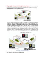
• The common rail system was developed primarily to cope with exhaust gas regulations for diesel engines, and aimed for
1. further improved fuel economy; 2. noise reduction; and 3. high power output.
A. System Characteristics
The common rail system uses a type of accumulation chamber called a rail to store pressurized fuel, and injectors that
contain electronically controlled solenoid valves to spray the pressurized fuel into the cylinders. Because the engine ECU
controls the injection system (including the injection pressure, injection rate, and injection timing), the injection system is
unaffected by the engine speed or load. This ensures a stable injection pressure at all times, particularly in the low engine
speed range, and dramatically decreases the amount of black smoke ordinarily emitted by a diesel engine during start-
up and acceleration. As a result, exhaust gas emissions are cleaner and reduced, and higher power output is achieved.
a. Injection Pressure Control
• Enables high-pressure injection even at low engine speeds.
• Optimizes control to minimize particulate matter and NOx emissions.
b. Injection Timing Control
Enables finely tuned optimized control in accordance with driving conditions.
c. Injection Rate Control
Pilot injection control sprays a small amount of fuel before the main injection.
Common Rail System
Optimization
Pilot injection
Main
injection
Injection Pressure Control
Injection Timing Control
Injection Rate Control
Injection Quantity Control
Injection
pressure
Speed
Speed
Crankshaft angle
Conventional
pump
Common rail system
Conventional
pump
Common rail system
Cylinder injection
volume correction
㧝㧟㧠㧞
Optimization, High pressurization
Injection pressure
Injection timing
Particulate
Speed
Injection rate
QD0734E
NOx
-3-
B. Comparison to the Conventional System
System
Common rail system
Injection quantity control
Pump (governor)
Injection timing control
Pump (timer)
Rising pressure
Pump
Distributor Pump
Injection pressure control
Dependent upon speed and injection quantity
High-pressure pipe
Momentary high pressure
Nozzle
Governor
Timer
In-line pump
VE pump
Rail
Usually high pressure
Supply pump
Injector
*1 TWV: Two Way Valve *2 SCVSuction Control Valve
QD2341E
Feed pump
SCV (suction control valve)
Delivery valve
Fuel tank
TWV
In-line, VE Pump
Engine ECU, injector (TWV)*
1
Engine ECU, injector (TWV)*
1
Engine ECU, supply pump
Engine ECU, rail
Engine ECU, supply pump (SCV)*
2
-4-
2-2. Outline of System
A. Main System Components
Q000045E
Injector
Supply pump
Rail
Engine coolant
temperature sensor
EGR volume
control valve
Mass airflow sensor
Variable nozzle
turbocharger control
actuator
Glow plug
Park/neutral position switch
Glow relay
Crankshaft position sensor
Items are DENSO products.
-5-
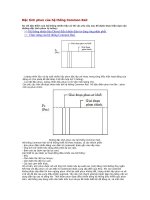
B. Composition
The common rail system consists primarily of a supply pump, rail, injectors, and ECU.
C. Operation
a. Supply Pump (HP3)
The supply pump draws fuel from the fuel tank, and pumps the high pressure fuel to the rail. The quantity of fuel dis-
charged from the supply pump controls the pressure in the rail. The SCV (Suction Control Valve) in the supply pump
effects this control in accordance with the command received from the ECU.
b. Rail
The rail is mounted between the supply pump and the injector, and stores the high-pressure fuel.
c. Injector
This injector replaces the conventional injection nozzle, and achieves optimal injection by effecting control in accordance
with signals from the ECU. Signals from the ECU determine the length of time and the timing in which current is applied
to the injector. This in turn, determines the quantity, rate and timing of the fuel that is injected from the injector.
d. Engine ECU
The engine ECU calculates data received from the sensors to comprehensively control the injection quantity, timing and
pressure, as well as the EGR (exhaust gas recirculation).
Q000046E
Fuel temperature sensor
Vehicle speed
Accelerator opening
Intake air pressure
Intake air temperature
Coolant temperature
Crankshaft position
Cylinder recognition sensor
Engine ECU
Rail
Intake airflow rate
Rail pressure sensor
Supply pump
Fuel temperature sensor
SCV
(suction
control valve)
Pressure
discharge
valve
Check valve
Fuel tank
Injector
EDU
-6-
D. Fuel System
This system comprises the route through which diesel fuel flows from the fuel tank to the supply pump, via the rail, and
is injected through the injector, as well as the route through which the fuel returns to the tank via the overflow pipe.
E. Control System
In this system, the engine ECU controls the fuel injection system in accordance with the signals received from various
sensors. The components of this system can be broadly divided into the following three types: (a) Sensors; (b) ECU; and
(c) Actuators.
a. Sensors
Detect the engine and driving conditions, and convert them into electrical signals.
b. Engine ECU
Performs calculations based on the electrical signals received from the sensors, and sends them to the actuators in order
to achieve optimal conditions.
c. Actuators
Operate in accordance with electrical signals received from the ECU. Injection system control is undertaken by electron-
ically controlling the actuators. The injection quantity and timing are determined by controlling the duration and the timing
in which the current is applied to the TWV (Two-Way Valve) in the injector. The injection pressure is determined by con-
trolling the SCV (Suction Control Valve) in the supply pump.
Crankshaft Position Sensor NE
Accelerator position sensor
Engine speed
Cylider recognition sensor G
Cylinder recognition
Load
Injector
Supply pump (SCV)
•Injection quantity control
•Injection timing control
•Injection pressure control
•Fuel pressure control
Other sensors and switches
EGR, air intake control relay, light
Sensor
Actuator
Q000047E
Engine
ECU
-7-
3. Construction and Operation
3-1. Description of Main Components
A. Supply Pump (HP3)
a. Outline
• The supply pump consists primarily of the pump body (eccentric cam, ring cam, and plungers), SCV (Suction Control
Valve), fuel temperature sensor, and feed pump.
• The two plungers are positioned vertically on the outer ring cam for compactness.
• The engine drives the supply pump at a ratio of 1:2. The supply pump has a built-in feed pump (trochoid type), and draws
the fuel from the fuel tank, sending it to the plunger chamber.
• The internal camshaft drives the two plungers, and they pressurize the fuel sent to the plunger chamber and send it to
the rail. The quantity of fuel supplied to the rail is controlled by the SCV, using signals from the engine ECU. The SCV is
a normally opened type (the intake valve opens during de-energization).
Q000048E
Fuel temperature sensor
To rail
From fuel tank
SCV
QD0704E
Injector
Rail
Discharge valve
Intake valve
Plunger
Return spring
Intake pressure
Feed pressure
High pressure
Return pressure
Regulating valve
Feed pump
Fuel inlet
Intake
Fuel filter (with priming pump)
Camshaft
Filter
Return
Fuel overflow
Fuel tank
-8-
b. Supply Pump Exploded Diagram
Q000049E
SCV
Pump body
Feed pump
Filter
Regulating valve
Ring cam
Drive shaft
Plunger
-9-
c. Supply Pump Internal Fuel Flow
The fuel that is drawn from the fuel tank passes through the route in the supply pump as illustrated, and is fed into the rail.
d. Construction of Supply Pump
• The eccentric cam is attached to the drive shaft. The eccentric cam is connected to the ring cam.
• As the drive shaft rotates, the eccentric cam rotates in the eccentric state, and the ring cam moves up and down while
rotating.
Supply pump interior
Regulating valve
Feed pump
Overflow
Fuel tank
SCV (Suction Control Valve)
Intake valve
Discharge valve
Pumping portion (plunger)
Rail
QD0705E
QD0706E
Drive shaft
Eccentric cam
Ring cam
QD0727E
Ring cam
Eccentric cam
Drive shaft
Plunger
-10-
• The plunger and the suction valve are attached to the ring cam. The feed pump is connected to the rear of the drive shaft.
e. Operation of the Supply Pump
As shown in the illustration below, the rotation of the eccentric cam causes the ring cam to push Plunger A upwards. Due
to the spring force, Plunger B is pulled in the opposite direction to Plunger A. As a result, Plunger B draws in fuel, while
Plunger A pumps it to the rail.
QD0728E
Plunger A
Ring cam
Feed pump
Plunger B
SCV
Plunger B
Plunger A
Eccentric cam
Delivery valve
Suction valve
Ring cam
Plunger A: complete compression
Plunger B: complete intake
Plunger A: complete intake
Plunger B: complete compression
Plunger B: begin compression
Plunger A: begin intake
Plunger B: begin intake
Plunger A: begin compression
QD0707E
-11-
B. Description of Supply Pump Components
a. Feed Pump
The trochoid type feed pump, which is integrated in the supply pump, draws fuel from the fuel tank and feeds it to the two
plungers via the fuel filter and the SCV (Suction Control Valve). The feed pump is driven by the drive shaft. With the ro-
tation of the inner rotor, the feed pump draws fuel from its suction port and pumps it out through the discharge port. This
is done in accordance with the space that increases and decreases with the movement of the outer and inner rotors.
b. SCV: Suction Control Valve
• A linear solenoid type valve has been adopted. The ECU controls the duty ratio (the length of time that the current is
applied to the SCV), in order to control the quantity of fuel that is supplied to the high-pressure plunger.
• Because only the quantity of fuel that is required for achieving the target rail pressure is drawn in, the actuating load of
the supply pump decreases.
• When current flows to the SCV, variable electromotive force is created in accordance with the duty ratio, moving the ar-
mature to the left side. The armature moves the cylinder to the left side, changing the opening of the fuel passage and
thus regulating the fuel quantity.
• With the SCV OFF, the return spring contracts, completely opening the fuel passage and supplying fuel to the plungers.
(Full quantity intake and full quantity discharge)
• When the SCV is ON, the force of the return spring moves the cylinder to the right, closing the fuel passage (normally
opened).
• By turning the SCV ON/OFF, fuel is supplied in an amount corresponding to the actuation duty ratio, and fuel is dis-
charged by the plungers.
QD0708E
Inner rotor
Intake port
Outer rotor
to Pump chamber
from Fuel tank
Discharge
port
Quantity decrease
Quantity increase
Quantity decrease (fuel discharge)
Quantity increase (fuel intake)
Q000050E
Exterior view of SCV
Cross-section of SCV
Pump body
SCV
-12-
(1) In case of short duty ON
Short duty ON => large valve opening => maximum intake quantity
Feed pump
SCV
Large opening
Cylinder
Cylinder
Plunger
Q000051E
-13-
(2) In case of long duty ON
Long duty ON => small valve opening => minimum intake quantity
Feed pump
SCV
Small opening
Cylinder
Q000052E
Cylinder
Plunger
-14-
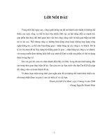
C. Rail
a. Outline
• Stores pressurized fuel (0 to 180 MPa) that has been delivered from the supply pump and distributes the fuel to each
cylinder injector. A rail pressure sensor and a pressure limiter are adopted in the rail.
• The rail pressure sensor (Pc sensor) detects the fuel pressure in the rail and sends a signal to the engine ECU, while the
pressure limiter controls the fuel pressure in the rail. This ensures optimum combustion and reduces combustion noise.
b. Rail Pressure (Pc) Sensor
This sensor detects fuel pressure in the rail and sends a signal to the ECU. It is a semi-conductor type pressure sensor
that utilizes the characteristic whereby electrical resistance changes when pressure is applied to silicon.
c. Pressure Limiter (made by another manufacturer)
The pressure limiter relieves pressure by opening the valve if abnormally high pressure is generated. The valve opens
when pressure in the rail reaches approximately 200 MPa, and closes when pressure falls to approximately 50 MPa. Fuel
leaked by the pressure limiter returns to the fuel tank.
Pressure limiter
Rail pressure (Pc) sensor
QC0018E
GND (ground)
Vout
(output voltage)
Vcc
(supply voltage)
+5V
ECU
Pc
sensor
Vout [V]
GND
Vout
Vcc
Q000053E
Rail pressure [MPa]
4.2
0 200
1.0
Vcc = 5V
Spring
Ball (valve)
Pc
To the fuel tank
QC0020E
-15-
D. Injector
a. Outline
The injectors inject the high-pressure fuel from the rail into the combustion chambers at the optimum injection timing,
rate, and spray condition, in accordance with commands received from the ECU.
b. Characteristics
• A compact, energy-saving solenoid-control type TWV (Two-Way Valve) injector has been adopted.
• A hollow screw with a damper is fitted in the fuel leak pipe connection to improve the injection precision.
c. Construction
G
Pressurized fuel
(from Rail)
Solenoid valve
Control chamber
Command piston
Nozzle spring
Pressure pin
Nozzle needle
Valve spring
Seat area
Leak passage
Q000054E
-16-
d. Operation
The TWV solenoid valve opens and closes the outlet orifice to control the pressure in the control chamber, and the start
and end of injection.
(1) No injection
When no current is supplied to the solenoid, the spring force is stronger than the hydraulic pressure in the control cham-
ber. Thus, the solenoid valve is pushed downward, effectively closing the outlet orifice. For this reason, the hydraulic
pressure that is applied to the command piston causes the nozzle spring to compress. This closes the nozzle needle,
and as a result, fuel is not injected.
(2) Injection
• When current is initially applied to the solenoid, the attraction of the solenoid pulls the TWV up, effectively opening the
outlet orifice and allowing the fuel to flow out of the control chamber. After the fuel flows out, the pressure in the control
chamber decreases, pulling the command piston up. This causes the nozzle needle to rise and injection to start.
• The fuel that flows past the outlet orifice flows to the leak pipe and below the command piston. The fuel that flows below
the nozzle needle lifts the it upward, which helps to improve the nozzle's opening and closing response.
• When current continues to be applied to the solenoid, the nozzle reaches its maximum lift, where the injection rate is also
at the maximum level. When current to the solenoid is turned OFF, the TWV falls, causing the nozzle needle to close
immediately and the injection to stop.
Attraction force > spring force
Attraction
force
Spring force
to Leak pipe
Injection
Spring force > hydraulic pressure force
Hydraulic
pressure force
Spring force
from Rail
No injection
TWV
Solenoid
Inlet orifice
Outlet orifice
Control chamber
Q000055E
Command piston
Nozzle spring
Nozzle needle
from Rail
-17-
e. Harness Connector with Correction Resistor
A correction resistor is provided in the harness connector (4-pin connector) of each injector to minimize the variances in
the injection volume among the cylinders (adjusted in the production line).
QD1167E
Solenoid side
Vehicle harness side
Correction
resistor
Solenoid
-18-
3-2. Description of Control System Components
A. Engine Control System Diagram
Q000056E
14.5
11.5
Park/neutral position switch
Cooling fan
ECU
Malfunction indicator
Glow light
IG ST
Battery
Vaccum
tank
Vaccum pump
EGR volume
control valve
Charge air pressure sensor
EGR cooler
Fuel injector
Fuel return
Rail fuel pressure sensor
Rail
Suction control
valve
Fuel temperature
sensor
Supply
pump
Engine
coolant
temp.
sensor
Crankshaft position
sensor
Accelerator pedal
position sensor
Charge air cooler
Accelerator pedal released
position switch
Glow plug
Variable nozzle
turbocharger
Mass airflow
sensor
Air
cleaner
Variable nozzle
turbocharger
control actuator
Variable nozzle
turbocharger
control solenoid
valve
Cylinder recognition
sensor
Catalyst
-19-
B. ECU (Electronic Control Unit)
a. Outline
• This is the command center that controls the fuel injection system and engine operation in general.
• The EDU is contained inside the ECU. The EDU has been adapted to support the high-speed actuation of the injectors.
The high-speed actuation of the injector solenoid valve is made possible through the use of a high-voltage generating
device (DC/DC converter).
b. EDU Operation
The high-voltage generating device converts the battery voltage into a high voltage. The Engine ECU sends signals to
terminals B through E of the EDU in accordance with the signals from the sensors. Upon receiving these signals, the
EDU outputs signals to the injectors from terminals H through K.
'0)+0'%10641.
QC0028E
[Outline diagram]
Sensor Engine ECU Actuator
Detection
Calculation Actuation
Q000057E
GND
COM
INJ#1
A
B
C
D
E
F
G
High voltage
generating circuit
Control
circuit
INJ#2
INJ#3
INJ#4
M
IJt#1
IJt#2
IJt#3
IJt#4
Battery
+B
IJf
GND
H
I
J
K
L
[Schematic diagram]
ECU
EDU
Injector
IJf
IJt
CPU
-20-
C. Description of Sensors
a. Crankshaft Position Sensor (NE)
An NE pulsar attached to the crankshaft timing gear outputs a signal for detecting the crankshaft angle and engine speed.
b. Cylinder Recognition Sensor (G)
A cylinder recognition sensor (G pulsar) is attached to the supply pump timing gear, and outputs a cylinder recognition
signal so that the ECU can calculate fuel injection timing.
ECU
NE input circuit
Exterior Drawing
Circuit Diagram
NE+
Q000058E
NE-
Vcc
NE+
NE-
Vcc
Vcc
Exterior View Diagram
G+
Q000059E
Vcc
ECU
G input circuit
Circuit Diagram
G+
G-
Vcc
Vcc
G-
-21-
c. Fuel Temperature Sensor (THF)
• The fuel temperature sensor is mounted on the supply pump, and detects the fuel temperature, sending a signal to the
engine ECU.
• The detection component utilizes a thermistor.
-30 (25.4)
15.0±1.5
-20
-10 (9.16)
0 (5.74)
10 (3.70)
20
30 (1.66)
40 (1.15)
50 (0.811)
60 (0.584)
70 (0.428)
80 0.318±0.031
90 (0.240)
100 (0.1836)
110 (0.1417)
120
(0.1108)
2.45±0.24
Q000060E
Temperature
(°C)
Resistance value
(kΩ)
Resistance Value Characteristics
Thermistor
Fuel temperature
sensor
-22-
3-3. Various Types of Controls
A. Outline
This system effects fuel injection quantity and injection timing control more appropriately than the mechanical governor
and timer used in the conventional injection pump. The engine ECU performs the necessary calculations in accordance
with the sensors installed on the engine and the vehicle. It then controls the timing and duration of time in which current
is applied to the injectors, in order to realize both optimal injection and injection timing.
a. Fuel Injection Quantity Control Function
The fuel injection quantity control function replaces the conventional governor function. It controls the fuel injection to an
optimal injection quantity based on the engine speed and accelerator position signals.
b. Fuel Injection Timing Control Function
The fuel injection timing control function replaces the conventional timer function. It controls the injection to an optimal
timing based on the engine speed and the injection quantity.
c. Fuel Injection Rate Control Function
Pilot injection control injects a small amount of fuel before the main injection.
d. Fuel Injection Pressure Control Function (Rail Pressure Control Function)
The fuel injection pressure control function (rail pressure control function) controls the discharge volume of the pump by
measuring the fuel pressure at the rail pressure sensor and feeding it back to the ECU. It effects pressure feedback con-
trol so that the discharge volume matches the optimal (command) value set in accordance with the engine speed and
the injection quantity.
-23-
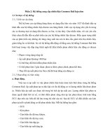
B. Fuel Injection Quantity Control
a. Outline
This control determines the fuel injection quantity by adding coolant temperature, fuel temperature, intake air tempera-
ture, and mass airflow corrections to the basic injection quantity that is calculated by the engine ECU, based on the en-
gine operating conditions and driving conditions.
b. Injection Quantity Calculation Method
c. Basic Injection Quantity
The basic injection quantity is determined by the engine speed (NE) and the accelerator position. The injection quantity
is increased when the accelerator position signal is increased while the engine speed remains constant.
Accelerator position
Accelerator position
Engine speed
Engine speed
Basic injection
quantity
Maximum injection
quantity
Final injection
quantity after
correction
Engine speed
Driver actuation
timing calculation
The basic injection quantity is obtained through the governor pattern
calculated from the accelerator position and the engine speed.
The basic injection quantity is then compared to the maximum
injection quantity obtained from the engine speed, to which various
types of corrections are made. The smallest injection quantity is then
used as the basis for the final injection quantity.
Injection quantity
Smaller quantity
Q000061E
Injection quantity
Mass airflow correction
Intake air temperature correction
Atmospheric pressure correction
Cold operation maximum injection quantity correction
Individual cylinder correction
Speed correction
Injection pressure correction
Accelerator position
Engine speed
QC0038E
Basic injection quantity