The roles of the various plasma agents in the inactivation of bacteria
Bạn đang xem bản rút gọn của tài liệu. Xem và tải ngay bản đầy đủ của tài liệu tại đây (452.34 KB, 5 trang )
The roles of the various plasma agents in the inactivation of bacteria
XinPei Lu,
1,a͒
Tao Ye,
2
YingGuang Cao,
2
ZiYong Sun,
2
Qing Xiong,
1
ZhiYuan Tang,
1
ZhiLan Xiong,
1
Jing Hu,
1
ZhongHe Jiang,
1
and Yuan Pan
1
1
College of Electrical and Electronics Engineering, Huazhong University of Science and Technology,
Wuhan, Hubei 430074, People’s Republic of China
2
Tongji Medical College, Huazhong University of Science and Technology, Wuhan, Hubei 430030, People’s
Republic of China
͑Received 21 May 2008; accepted 9 July 2008; published online 15 September 2008͒
The roles of various plasma agents in the inactivation of bacteria have recently been investigated.
However, up to now, the effect of the charged particles on the inactivation of bacteria is not well
understood. In this paper, an atmospheric pressure plasma jet device, which generates a cold plasma
plume carrying a peak current of 300 mA, is used to investigate the role of the charged particles in
the inactivation process. It is found that the charged particles play a minor role in the inactivation
process when He/ N
2
͑3%͒ is used as working gas. On the other hand, when He/ O
2
͑3%͒ is used, the
charged particles are expected to play an important role in the inactivation of bacteria. Further
analysis shows that the negative ions O
2
−
might be the charged particles that are playing the role.
Besides, it is found that the active species, including O, O
3
, and metastable state O
2
ء
, can play a
crucial role in the inactivation of the bacteria. However, the excited He
ء
,N
2
C
3
⌸
u
, and N
2
+
B
2
⌺
u
+
have no significant direct effect on the inactivation of bacteria. It is also concluded that heat and UV
play no or minor role in the inactivation process. © 2008 American Institute of Physics.
͓DOI: 10.1063/1.2977674͔
I. INTRODUCTION
One of the most attractive features of nonequilibrium
plasmas is their enhanced plasma chemistry. The plasma
chemistry is driven by the electrons, which gain energy from
the applied electric field. Due to several orders of difference
in mass between the electrons and the heavy particles, the
heavy particles can remain at low temperature while under-
going frequent collisions with the energized electrons. The
collisions between the energized electrons and the heavy par-
ticles result in enhanced levels of excitation, dissociation,
and ionization, i.e., enhanced plasma chemistry. It has re-
cently been demonstrated that narrow voltage pulses are fa-
vorable for enhanced plasma chemistry.
1–7
Because of the enhanced plasma chemistry, atmospheric
pressure nonequilibrium plasmas ͑APNPs͒ have been widely
studied for several emerging novel applications such as sur-
face and materials processing, biological and chemical de-
contaminations of media, absorption and reflection of elec-
tromagnetic radiation, and synthesis of nanomaterials.
8–26
Among the novel applications, the use of APNPs in the bio-
medical field, such as sterilization, is attracting significant
attention. Traditionally, the principal methods of inactivation
of bacteria are based on thermal treatment ͑dry or moist
heat͒, chemical treatment ͑e.g., H
2
O
2
and EtO͒, or radiation
͑x ray and
␥
-ray͒. However, each of the conventional meth-
ods has its inherent drawbacks. They either are not suitable
for the treatment of temperature sensitive materials or have
residue toxic gases or raise significant safety concerns.
For the APNPs used for biomedical applications, their
gas temperatures are generally required to stay close to or at
room temperature. Therefore, unlike thermal treatment, they
can be used for treatment of temperature sensitive materials.
Besides, the chemically reactive species generated by the
plasmas have relatively short lifetime. When the plasmas are
turned off, there is no residue gas as in the case of common
chemical treatment. Furthermore, there is no harmful radia-
tion emitted by the plasmas. The APNPs offer very practical
and safe sterilization method, where x-ray or
␥
-ray radiation
method does not.
When the APNPs are used for sterilization, the potential
active plasma agents are UV radiation, heat, and chemically
reactive species and charged particles. The role of UV radia-
tion depends on the wavelength and the power density of
UV. The UV doses of several mW s/ cm
2
are required to have
a significant effect on the inactivation of bacteria, which is
not fulfilled for atmospheric pressure air plasma.
27
The effect
of heat is normally avoided when the gas temperature of the
plasma is at room temperature. Therefore, it is widely ac-
cepted that when remote exposure is used, chemically reac-
tive species such as reactive oxygen species ͑ROS͒ and re-
active nitrogen species ͑O, O
3
, NO, NO
2
͒ play the crucial
roles in the inactivation of bacteria.
14
However, the contribu-
tion of each type of the reactive species is not well under-
stood. Regarding the role of the charged particles, Mendis et
al.
28
and Laroussi et al.
14
suggest that when direct treatment
͑bacterial samples are placed inside a discharge gap͒ is em-
ployed, the charged particles may have some effects on the
inactivation of bacteria. However, when the bacterial
samples are placed inside a dielectric barrier discharge
͑DBD͒ discharge gap, as did by Fridman et al.,
13
high elec-
tric field is also imposed on the bacteria. The high electric
field may have a significant effect on the inactivation of bac-
teria too.
a͒
Author to whom correspondence should be addressed. Electronic mail:
JOURNAL OF APPLIED PHYSICS 104, 053309 ͑2008͒
0021-8979/2008/104͑5͒/053309/5/$23.00 © 2008 American Institute of Physics104, 053309-1
Downloaded 15 Sep 2008 to 211.69.195.192. Redistribution subject to AIP license or copyright; see />In this paper, a recently developed plasma jet device,
which generates a cold plasma plume with high discharge
current, is used to investigate the contribution of the charged
particles to the inactivation of bacteria. The plasma plume
carries a peak current of about 300 mA as reported in Ref. 6.
In the mean time, the electric field along the plasma plume is
believed to be extremely low since a human finger can touch
any part of the plasma plume without any feeling of electri-
cal shock. This remarkable characteristic enables us to dis-
tinguish the role of the charged particles from that of the
electric field, which should be negligible. Besides, the roles
of the active species, heat, and UV in the inactivation process
are also investigated in this paper.
II. EXPERIMENT SETUP
Figures 1͑a͒ and 1͑b͒ are the schematic of the experi-
ment setup for direct and indirect treatments, respectively.
The high voltage ͑HV͒ wire electrode, which is made of a
copper wire with a diameter of 2 mm, is inserted intoa4cm
long quartz tube with one end closed. The inner and outer
diameters of the quartz tube are 2 and 4 mm, respectively.
The quartz tube along with the HV electrode is inserted into
a hollow barrel of a syringe. The diameter of the hollow
barrel is about 6 mm and the diameter of the syringe nozzle
is about 1.2 mm. The distance between the tip of the HV
electrode and the nozzle is 1 cm. Details on the experiment
setup can be found in Ref. 6. When working gas such as
helium, argon, oxygen, and nitrogen or its mixtures with a
flow rate of a few l/min are injected into the hollow barrel
and the HV pulsed dc voltage ͑amplitudes of up to 10 kV,
repetition rate of up to 10 khz, and pulse width variable from
200 ns to dc͒ is applied to the HV electrodes, a homogeneous
plasma is generated in front of the end of the quartz tube,
along the nozzle, and in the surrounding air. The length of
the plasma plume can reach as long as 6 cm with helium as
working gas.
To investigate the role of the charged particles in the
inactivation process, the bacterial samples are treated by the
plasma plume in two different ways, i.e., direct and indirect
treatments. For the direct treatment, the bacterial samples on
the agar plates are placed right under the plasma plume at an
adjustable distance x from the nozzle. The bacterial samples
are directly contacted with the plasma plume. For the indi-
rect treatment, the grounded thin wire with a diameter of 0.1
mm is placed at a distance x
1
=0.5 cm away from the nozzle
while the bacterial samples are placed at an adjustable dis-
tance x
2
from the thin wire. Since the diameter of the thin
wire is much smaller than that of the nozzle, the influence of
the thin wire on the gas flow dynamic is expected to be
negligible. This is also confirmed by our following experi-
mental results. Figures 1͑c͒ and 1͑d͒ show the photographs
of the plasma plume when it is used for the direct and indi-
rect treatments. Figure 1͑d͒ clearly shows that the plasma
plume stops at the thin wire. It should be pointed out that
when the thin wire is not directly connected to the ground,
such as grounded through a 2 M⍀ resistor or even floating,
the luminous part of the plasma plume also stops at the thin
wire. However, when the thin wire is directly connected to
the ground, the plasma is disturbed significantly. Therefore,
for all the inactivation experiments of indirect treatment
shown in this paper, to minimize the disturbance of the thin
wire, the wire is actually connected to the ground through a
2M⍀ resistor.
The bacterial samples that are treated by the plasma
plume are prepared as follows: Staphylococcus aureus,a
gram-positive bacterium, is selected for this experiment. An
overnight culture containing approximately 10
8
cfu/ ml is
prepared. Then the culture is diluted to 10
6
cfu/ ml ͑cfu:
colony-forming unit͒ for the experiments. 200
l of the di-
luted suspension containing bacterium concentrations of
10
6
cfu/ ml is evenly spread over each agar plate in Petri
dish. Afterward, it is treated by the plasma plumes for 2 min
immediately. After the plasma treatment, it is incubated for
24 h at 37 °C. For control experiments, the samples are
treated by the working gas flowing at the same flow rate with
plasma off. It should be pointed out that all the experiments
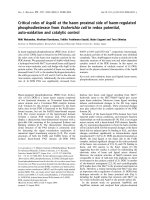
FIG. 1. ͑Color online͒ Experimental setup and photographs of the plasma plume. ͑a͒ For direct treatment, where x is the distance between the jet nozzle and
the bacterial samples. ͑b͒ For indirect treatment, where x
1
is the distance between the jet nozzle and the thin ground wire, and x
2
is the distance between the
thin ground wire and the bacterial samples. ͑c͒ and ͑d͒ are the photographs of the plasma plume when it is used for direct and indirect treatments, respectively.
053309-2 Lu et al. J. Appl. Phys. 104, 053309 ͑2008͒
Downloaded 15 Sep 2008 to 211.69.195.192. Redistribution subject to AIP license or copyright; see />reported in this letter are repeated four times, and the results
are consistent with the same experimental conditions.
III. EXPERIMENTAL RESULTS AND DISCUSSION
A. The role of the charged particles
The first group of the experiment is done with
He/ N
2
͑3%͒ at a flow rate of 2 l/min. For the control experi-
ment, the bacterial samples are treated by the He/ N
2
͑3%͒ at
the same flow rate with plasma off ͑power off͒. For all the
inactivation experiments reported in this letter, the pulse fre-
quency f of 4 kHz, pulse width t
pw
of 1.6
s, and applied
voltage V of 9 kV are fixed. Figures 2͑a͒–2͑h͒ show the
experimental results. Areas, where bacteria are killed, look
like uncontaminated agar ͑black͒ while areas that were not
affected change color ͑gray͒ and appearance significantly as
the bacteria grow there. According to these photographs, it
can be concluded that with plasma off, the flowing of
He/ N
2
͑3%͒ gas has no effect on the growth of the bacteria.
Since the plasma plume stops at the thin wire, it is rea-
sonable to assume that there are no significant charged par-
ticles reaching the bacterial samples for the indirect treat-
ment. Figures 2͑f͒–2͑h͒ show that the affected areas do not
reduce at all for the indirect treatment results. Therefore, it
can be concluded that the charged particles play a minor role
in the inactivation process for the He plasma plume, and the
ground wire has negligible effect on the gas flow dynamic.
As was reported in Ref. 6, the peak current carried by the
plasma plume reaches more than 300 mA. So, the peak elec-
tron density of the plasma plume can be estimated according
to the diameter of the nozzle and electron drift velocity. It is
in the order of 10
13
/ cm
3
. Hence, it is suspected that the con-
centration of the charged particles is much lower than that of
the active free radicals.
The second group of the experiment is conducted with
He/ O
2
͑3%͒ as working gas at a flow rate of 2 l/min. Figures
3͑a͒–3͑d͒ show the test results for the direct and indirect
treatments ͑To save space, the control experiment results are
not shown here, which indicate that the gas flow has no
effect on the inactivation of bacteria͒. It clearly shows that
the affected areas for both the direct and indirect treatments
are much larger than those in Fig. 2. This will be discussed in
Sec. III C. It should be stressed that according to Fig. 3, the
affected areas of the direct treatment are much larger than
those of the indirect treatment. As has been demonstrated
that the ground wire for the indirect treatment should mainly
affect the contribution of the charged particles to the inacti-
vation process; therefore, the charged particles should play a
significant role in this case. This observation is opposite to
that obtained with He/ N
2
as working gas. As we know that
when He/ N
2
is used as working gas, the dominant ions are
He
+
,He
2
+
,orN
2
+
ions. Their densities should be close to those
of electrons, i.e., in the order of 10
13
cm
−3
. On the other
hand, when He/ O
2
mixture is used as working gas, besides
He
+
,He
2
+
,O
2
+
, and electrons, high concentration of negative
ion O
2
−
may be present in the plasma. The O
2
−
is formed
mainly through the following reaction:
e +O
2
+ M → O
2
−
+ M, ͑1͒
where M is the third body, which is O
2
or He for this experi-
ment. For simplicity, we assume that the reaction rates of Eq.
͑1͒ for the third body O
2
and He are the same. The reaction
rate of Eq. ͑1͒ can be expressed as k
1
=1.4
ϫ10
−29
͑300/ T
e
͒exp͑−600/ T͒exp͓700ϫ͑T
e
−T͒ / T
e
T͔ cm
6
s
−1
.
29
Assuming T = 300 K and T
e
=1 eV, the
characteristic time of the process described by Eq. ͑1͒ is
estimated to be about 8 ns. In other words, it takes about 8 ns
for an electron to form an O
2
−
ion. This is much shorter than
FIG. 2. Photographs of staphylococ-
cus aureus samples on agar in Petri
dishes. Working gas He/ N
2
͑3%͒͑flow
rate of 2 l/min͒. ͓͑a͒–͑d͔͒ Direct treat-
ment: ͑a͒ control experiment, ͓͑b͒–͑d͔͒
bacterial samples placed at different
distances x
2
=1.5 from the nozzle.
͓͑e͒–͑h͔͒ Indirect treatment: ͑e͒ control
experiment, ͓͑f͒–͑h͔͒ bacterial samples
placed at different distances x
2
from
the thin wire, x
1
is fixed at 0.5 cm.
FIG. 3. Photographs of staphylococ-
cus aureus samples on agar in Petri
dishes. Working gas He/ O
2
͑3%͒͑flow
rate of 2 l/min͒. ͑a͒ and ͑b͒ are for di-
rect treatments with x =1.5 and 2.5 cm,
respectively. ͑c͒ and ͑d͒ are for indi-
rect treatments with x
2
=1.5 and 2.5
cm, respectively, x
1
is fixed at 0.5 cm.
053309-3 Lu et al. J. Appl. Phys. 104, 053309 ͑2008͒
Downloaded 15 Sep 2008 to 211.69.195.192. Redistribution subject to AIP license or copyright; see />the pulse width of the discharge current, which is about 100
ns.
6
Therefore, during the discharge current pulses, the con-
centration of O
2
−
ions might reach a value much higher than
that of electrons. Simulation of a low temperature air plasma
actually shows that the O
2
−
ion concentration can reach a few
orders higher than that of the electrons under certain
conditions.
30
However, further studies, including simulation
and experiment work, are still needed to confirm this conclu-
sion.
B. The role of excited N
2
ء
,N
2
+ء
, and He
ء
A half meter spectroscopy ͑Princeton Instruments Acton
SpectraHub 2500i͒ is used to measure the optical emission of
the plasma plume. Figure 4 shows the typical emission spec-
tra of the plasma plume for working gas of He/ N
2
͑3%͒ at a
flow rate of 2 l/min. It can be seen that the emission spectra
are dominated by the excited N
2
ء
, N
2
+
*
, and He
ء
. The experi-
ment on the spatial resolved emission spectra shows that the
N
2
͑C
3
⌸
u
→ B
3
⌸
g
͒,N
2
+
͑B
2
⌺
u
+
→ X
2
⌺
g
+
͒, and He
ء
emission
intensities from the plasma plume of 1.5 cm away from the
jet nozzle are about 5–10 times higher than those of 2.5 cm
away from the jet nozzle. However, Figs. 2͑b͒–2͑d͒ show
that the inactivation efficacy does not depend on the distance
where the samples are placed. So, the excited N
2
C
3
⌸
u
,N
2
+
B
2
⌺
u
+
, and He
ء
are not expected to play a significant direct
role in the inactivation process.
C. The roles of reactive oxygen species
It is widely agreed that the ROSs play a crucial role in
the inactivation process. This is also confirmed by our ex-
perimental results. When the working gas of He/ N
2
͑3%͒ is
replaced by He/O
2
͑3%͒, Figs. 3͑c͒ and 3͑d͒ show that the
affected areas are significantly enlarged. Since the charged
particles are collected by the thin wire, the improved inacti-
vation efficacy can only be attributed to the ROS. The po-
tential ROSs include atoms O, O
3
, and metastable state O
2
.
Figures 3͑c͒ and 3͑d͒ show that when the bacterial
samples are indirectly treated by the plasma plume at differ-
ent distances away from the ground wire electrode, the af-
fected areas are similar. Therefore, the agents that have sig-
nificant contribution to the inactivation process should have
lifetimes of milliseconds or longer so that their concentra-
tions will not decrease significantly at a few centimeters
away from the ground wire electrode where the samples are
placed. As we know, O
3
and some metastable state O
2
ء
, such
as O
2
͑a
1
⌬
g
͒, have lifetimes of millisecond range or longer.
Regarding O, the main reaction pathways that lead to the
consumption of O for He/ O
2
plasma are
O+O+M→
k
2
O
2
+ M, ͑2͒
O+O
2
+ M→
k
3
O
3
+ M, ͑3͒
O+O
3
→
k
4
O
2
+O
2
. ͑4͒
At room temperature, the reaction rates k
2
=3.6
ϫ10
−33
cm
6
s
−1
, k
3
=6.4ϫ10
−34
cm
6
s
−1
, and k
4
=8.3
ϫ10
−15
cm
3
s
−1
.
31
The concentrations of O and O
3
are esti-
mated to be less than 0.1%.
32
The lifetime of O can be esti-
mated by Eqs. ͑2͒–͑4͒. It is in millisecond range. So, O atom
can play a role under this condition.
D. The role of heat
To evaluate the inactivation role of heat, the gas tem-
perature of the plasma plume is determined by comparing
experimentally measured emission spectrum of the second
position system of nitrogen with simulated spectra at differ-
ent temperatures. The gas temperature is obtained when the
best fit of the simulated spectra and the measured spectrum
are achieved.
33
Figure 5 shows that the simulated spectrum
of rotational temperature of 300 K gives a good fit to the
measured spectrum. Therefore, the gas temperature of the
plasma plume is at room temperature.
E. The role of UV
The UV emission from the plasma plume is measured by
an UV photometer ͑International Light Technology, model
IL1400A͒. When we are measuring the UV intensity, the
Petri dish is removed and the detector of the UV photometer
is placed at the location. For all the tested working gases, the
measured UV emission intensity is around
0.05–0.1 mW/cm
2
. Therefore, the UV emission plays a mi-
nor role in the inactivation of the bacteria.
FIG. 4. Typical emission spectra of the plasma plume for He/ N
2
͑3%͒͑flow rate of 2 l/min͒.
053309-4 Lu et al. J. Appl. Phys. 104, 053309 ͑2008͒
Downloaded 15 Sep 2008 to 211.69.195.192. Redistribution subject to AIP license or copyright; see />Finally, for curiosity, about 50–100 ml of alcohol is
evenly spread on the center part of the bacterial sample with
an area of about 1.5 cm in diameter in the Petri dish. Figures
6͑a͒ and 6͑b͒ show the tested results for the control and
alcohol treated samples after incubation for 24 h at 37 ° C. It
clearly shows that the growth of the bacteria within the al-
cohol treated area is not significantly affected.
IV. CONCLUSION
In this paper, a specially designed plasma jet device,
which generates a room temperature plasma plume with a
peak discharge current of about 300 mA, is used to study the
role of the various plasma agents in the inactivation process.
By using a thin wire to collect the charged particles, the role
of the charged particles in the inactivation process is studied.
When He/ N
2
͑3%͒ is used as the working gas, it is found that
the charged particles do not play a significant role in the
inactivation process. On the other hand, when He/ O
2
͑3%͒ is
used, the charged particles are expected to play a crucial role
in the inactivation of bacteria. Because of the fast attachment
rate of electron and O
2
, it is concluded that the O
2
−
might be
the charged particles playing the role. This behavior is simi-
lar to common effects in a dusty plasma, where negative ions
can take part in the charging of dusty particles.
34
Begum et
al.
35
recently confirmed that the plasma plume is actually
negatively charged.
In addition, by placing the bacterial samples at different
distances away from the jet nozzle, according to the spatial
resolved emission spectra of the plasma plume, it is con-
cluded that the excited N
2
ء
,N
2
+ء
, and He
ء
have no significant
direct effect on the inactivation of bacteria. Furthermore, by
comparing the inactivation experiment results of He/ N
2
͑3%͒
plasma with those of He/ O
2
͑3%͒ plasma, it is concluded that
the ROSs, including the O
3
, metastable state O
2
, and atom O,
which is estimated to have a lifetime in the millisecond
range, are playing the main role in the inactivation process.
Finally, the measurements of the UV intensity show that the
UV emission is too weak to play a crucial direct role in the
inactivation process.
ACKNOWLEDGMENTS
This work is supported by the Chang Jiang Scholars Pro-
gram, Ministry of Education, People’s Republic of China.
1
S. Liu and M. Neiger, J. Phys. D 34, 1632 ͑2001͒.
2
M. Laroussi, X. Lu, V. Kolobov, and R. Arslanbekov, J. Appl. Phys. 96,
3028 ͑2004͒.
3
X. Lu and M. Laroussi, J. Phys. D 39,1127͑2006͒.
4
X. Lu and M. Laroussi, J. Appl. Phys. 100, 063302 ͑2006͒.
5
X. Lu and M. Laroussi, Appl. Phys. Lett. 92, 051501 ͑2008͒.
6
X. Lu, Z. Jiang, Q. Xiong, Z. Tang, and Y. Pan, Appl. Phys. Lett. 92,
151504 ͑2008͒.
7
J. L. Walsh and M. G. Kong, Appl. Phys. Lett. 91, 221502 ͑2007͒.
8
R. Dorai and M. J. Kushner, J. Phys. D 36, 666 ͑2003͒.
9
Z. Machala, E. Marode, M. Morvova, and P. Lukac, Plasma Processes
Polym. 2, 152 ͑2005͒.
10
K. Ostrikov, Rev. Mod. Phys. 77, 489 ͑2005͒.
11
F. Leipold, R. H. Stark, A. EI-Habachi, and K. H. Schoenbach, J. Phys. D
33, 2268 ͑2000͒.
12
C. Jiang, A. A. Mohamed, R. H. Stark, J. H. Yuan, and K. H. Schoenbach,
IEEE Trans. Plasma Sci. 33, 1416 ͑2005͒.
13
G. Fridman, A. Brooks, M. Balasubramanian, A. Fridman, A. Gutsol, V.
Vasilets, H. Ayan, and G. Friedman, Plasma Processes Polym. 4,370
͑2007͒.
14
M. Laroussi, Plasma Processes Polym. 2, 391 ͑2005͒.
15
M. Laroussi, IEEE Trans. Plasma Sci. 30, 1409 ͑2002͒.
16
M. Laroussi, J. P. Richardson, and F. C. Dobbs, Appl. Phys. Lett. 81,772
͑2002͒.
17
J. J. Shi and M. G. Kong, IEEE Trans. Plasma Sci. 33, 276 ͑2005͒.
18
K. H. Becker, K. H. Schoenbach, and J. G. Eden, J. Phys. D 39,R55
͑2006͒.
19
E. Stoffels, I. E. Kieft, and R. E. J. Sladek, J. Phys. D 36, 2908 ͑2003͒.
20
I. Levchenko, K. Ostrikov, and E. Tam, Appl. Phys. Lett. 89, 223108
͑2006͒.
21
R. Vidmar, IEEE Trans. Plasma Sci. 18, 733 ͑1990͒.
22
M. Lee, S. Han, H. Baik, and K. Song, J. Appl. Phys. 101, 103305 ͑2007͒.
23
I. Levchenko, K. Ostrikov, M. Keidar, and S. Xu, J. Appl. Phys. 98,
064304 ͑2005͒.
24
D. Kim, J. Rhee, S. Moon, and W. Choe, Appl. Phys. Lett. 89, 061502
͑2006͒.
25
D. Kim, J. Rhee, B. Gweon, S. Moon, and W. Choe, Appl. Phys. Lett. 91,
151502 ͑2007͒.
26
X. Lu and M. Laroussi, J. Appl. Phys. 98, 023301 ͑2005͒.
27
M. Laroussi and F. Leipold, Int. J. Mass. Spectrom. 233,81͑2004͒.
28
D. A. Mendis, M. Rosenberg, and F. Azam, IEEE Trans. Plasma Sci. 28,
1304 ͑2000͒.
29
I. Kossyi, A. Kostinsky, A. Matveyev, and V. Silakov, Plasma Sources
Sci. Technol. 1, 207 ͑1992͒.
30
X. Lu, J. Appl. Phys. 102, 033302 ͑2007͒.
31
K. H. Becker, U. Kogelschatz, and K. H. Schoenbach, Non-Equilibrium
Air Plasmas at Atmospheric Pressure ͑IOP, London, 2005͒,p.133.
32
J. Jeong, J. Park, I. Henins, S. Babayan, V. Tu, G. Selwyn, G. Ding, and R.
Hicks, J. Phys. Chem. A 104,8027͑2000͒.
33
G. Faure and S. M. Shkol’nik, J. Phys. D 31, 1212 ͑1998͒.
34
K. Ostrikov, S. Kumar, and H. Sugai, Phys. Plasmas 8, 3490 ͑2001͒.
35
A. Begum, S. Dhali, and M. Laroussi, Proceedings of the 35th IEEE
International Conference on Plasma Science, Karlsruhe, Germany, 15–19
June, 2008 ͑unpublished͒, p. 146.
FIG. 5. ͑Color online͒ Simulated and measured rotational bands of the 0–0
transition of the second positive system of nitrogen. The spectra are inten-
tionally shifted vertically for better comparison.
FIG. 6. Photographs of staphylococcus aureus samples on agar in Petri
dishes. ͑a͒ Control and ͑b͒ treated by a drop of alcohol ͑50– 100 ml͒ on the
center part of the bacterial sample with a diameter of 1.5 cm in the Petri
dish.
053309-5 Lu et al. J. Appl. Phys. 104, 053309 ͑2008͒
Downloaded 15 Sep 2008 to 211.69.195.192. Redistribution subject to AIP license or copyright; see />