Toyota camry 2006 2011 navigation hệ thống định vị vị trí trên toyota camry đời 2006 2011
Bạn đang xem bản rút gọn của tài liệu. Xem và tải ngay bản đầy đủ của tài liệu tại đây (8.12 MB, 222 trang )
NAVIGATION – NAVIGATION SYSTEM
NS–1
NS
BODY ELECTRICALNAVIGATION
NAVIGATION SYSTEM
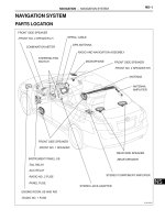
PARTS LOCATION
RADIO AND NAVIGATION ASSEMBLY
COMBINATION METER
ENGINE ROOM J/B AND R/B
INSTRUMENT PANEL J/B
ANTENNA
ANTENNA
AMPLIFIER
GPS ANTENNA
STEREO JACK ADAPTER
STEREO COMPONENT AMPLIFIER
MICROPHONE
SPIRAL CABLE
STEERING PAD
SWITCH
REAR SIDE SPEAKER
FRONT SIDE SPEAKER
FRONT SIDE SPEAKER
FRONT SIDE SPEAKER
-FRONT NO. 2 SPEAKER LH
-FRONT NO. 2 SPEAKER RH
-REAR SPEAKER
-FRONT NO. 1 SPEAKER
-TAIL RELAY
-PANEL FUSE
-RADIO NO. 2 FUSE
-ACC RELAY
-RADIO NO. 1 FUSE
E132176E01
NS–2
NAVIGATION – NAVIGATION SYSTEM
NS
SYSTEM DIAGRAM
Speakers
Stereo
Component
Amplifier
Steering Pad Switch
Switch Signal
Combination Meter
Vehicle Speed Signal
Park/Neutral Position Switch
Reverse Signal
Microphone Assembly
Microphone Voice Signal
Stereo Jack Adapter
External Device Sound Signal
Radio Antenna
GPS Antenna
Radio and
Navigation
Assembly
: Sound Signal
: AVC-LAN
Antenna Amplifier
E129832E02
NAVIGATION – NAVIGATION SYSTEM
NS–3
NS
SYSTEM DESCRIPTION
1. Radio and navigation assembly outline
(a) Conventionally, 2 separate devices, a "radio and
display" and a "navigation ECU" are used. This
model has adopted a new type, combining these
devices into a single unit.
Radio and Display
Navigation ECU
Radio and Navigation Assembly
E129826E01
NS–4
NAVIGATION – NAVIGATION SYSTEM
NS
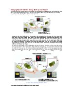
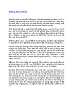
2. Navigation system outline
(a) Vehicle position tracking methods
It is essential that the navigation system correctly
tracks the current vehicle position and displays it on
the map. There are 2 methods to track the current
vehicle position: autonomous (dead reckoning) and
GPS* (satellite) navigation. Both navigation
methods are used in conjunction with each other.
*GPS (Global Positioning System)
GPS satellite
Location by
GPS navigation
GPS Antenna
GPS Antenna
Receive satellite radio wave
Vehicle Speed Sensor
Vehicle Speed Sensor
Detect vehicle running
distance
Navigation
Gyro Sensor
ECU
Location by autonomous
navigation
Detect the measurement position
GPS correction
Radio and Navigation Assembly
Create the current vehicle
position tracking data
Detect direction change
Gyro Sensor
Map matching correction
Map disc
Map scrolling
Map scale switching
Map and current vehicle position
data processing
Navigation screen
E120052E01
NAVIGATION – NAVIGATION SYSTEM
NS–5
NS
Operation Description
Vehicle Position Calculation
The radio and navigation assembly calculates the current vehicle
position (direction and current position) using the direction deviation
signal from the gyro sensor and the running distance signal from the
vehicle speed sensor and creates the driving route.
Map Display Processing
The radio and navigation assembly displays the vehicle track on the
map by processing the vehicle position data, vehicle running track,
and map data from the map disc.
Map Matching
The map data from the map disc is compared to the vehicle position
and running track data. Then, the vehicle position is matched with the
nearest road.
GPS Correction
The vehicle position is matched to the position measured by GPS.
Then, the measurement position data from the GPS unit is compared
with the vehicle position and running track data. If the position is
widely different, the GPS measurement position is used.
Distance Correction
The running distance signal from the vehicle speed sensor includes
the error caused by tire wear and slippage between the tires and road
surface. Distance correction is performed to account for this. The
radio and navigation assembly automatically offsets the running
distance signal to make up for the difference between it and the
distance data of the map. The offset is automatically updated.
Navigation is performed even where the GPS
radio wave does not reach.
Autonomous Navigation
Autonomous Navigation and
GPS Wave Navigation
GPS Satellite
In a tunnel
In an indoor parking lot
Between tall buildings
Under an overpass
On a forest or tree-lined path
I100028E07
NS–6
NAVIGATION – NAVIGATION SYSTEM
NS
HINT:
The combination of autonomous and GPS
navigation makes it possible to display the vehicle
position even when the vehicle is in places where
the GPS radio wave cannot receive a signal. When
only autonomous navigation is used, however, the
mapping accuracy may slightly decline.
(b) Autonomous navigation
This method determines the relative vehicle position
based on the running track determined by the gyro
and vehicle speed sensors located in the radio and
navigation assembly.
(1) Gyro sensor
Calculates the direction by detecting angular
velocity. It is located in the radio and navigation
assembly.
(2) Vehicle speed sensor
Used to calculate the vehicle running distance.
NAVIGATION – NAVIGATION SYSTEM
NS–7
NS
(c) GPS navigation (Satellite navigation)
This method detects the absolute vehicle position
using radio waves from a GPS satellite.
* GPS satellites were launched by the U.S.
Department of Defence for military purposes.
Number of satellites Measurement Description
2 or less Measurement impossible
Vehicle position cannot be obtained because
the number of satellites is not enough.
3 2-dimensional measurement is possible
Vehicle position is obtained based on the
current longitude and latitude. (This is less
precise than 3-dimensional measurement.)
4 3-dimensional measurement is possible
Vehicle position is obtained based on the
current longitude, latitude and altitude.
Current longitude/latitude/altitude is determined using the radio wave arrival time from four satellites.
GPS
I100029E03
NS–8
NAVIGATION – NAVIGATION SYSTEM
NS
(d) Map matching
The current driving route is calculated by
autonomous navigation (according to the gyro
sensor and vehicle speed sensor) and GPS
navigation. This information is then compared with
possible road shapes from the map data in the map
disc and the vehicle position is set onto the most
appropriate road.
A
Start
Map
Matching
Actual driving route
Driving route on the display
(Route by estimation)
Roads
L3L2
L1
The system compares the shape of the roads L1,
L2 and L3 to the estimated running track after the
vehicle makes a right turn. At point A, the vehicle
position differs enough from the shape of L1 that
the display switches to the road L2.
L
L
L
1
2
3
I100030E07
NAVIGATION – NAVIGATION SYSTEM
NS–9
NS
(e) Touch switch
Touch switches are touch-sensitive (interactive)
switches operated by touching the screen. When a
switch is pressed, the outer glass bends in to
contact the inner glass at the pressed position. By
doing this, the voltage ratio is measured and the
pressed position is detected.
3. DVD (Digital Versatile Disc) player outline (for
navigation map)
(a) The radio and navigation assembly (built-in
navigation ECU) uses a laser pickup to read the
digital signals recorded on a DVD.
HINT:
• Do not disassemble any part of the radio and
navigation assembly (built-in navigation ECU).
• Do not apply oil to the radio and navigation
assembly (built-in navigation ECU).
• Do not insert anything but a DVD into the radio
and navigation assembly (built-in navigation
ECU).
Outer
Inner
Glass
Vx1 (Vy1)
Vx2 (Vy2)
Vy1
Vy2
Vx1 Vx2
The touch switch detects the voltage ratio
and calculates the position on the screen.
Touch-sensitive switch position
Contact
E106414E03
NS–10
NAVIGATION – NAVIGATION SYSTEM
NS
CAUTION:
Do not look directly at the laser pickup because
the radio and navigation assembly (built-in
navigation ECU) uses an invisible laser beam.
Be sure to only operate the navigation system
as instructed.
4. CD (Compact Disc) player outline
(a) A compact disc player uses a laser pickup to read
digital signals recorded on a compact disc (CD). By
converting the digital signals to analog, it can play
music and other content.
NOTICE:
• Do not disassemble any part of the CD player.
• Do not apply oil to the CD player.
• Do not insert anything but a CD into the CD
player.
CAUTION:
Do not look directly at the laser pickup because
the CD player uses an invisible laser beam. Be
sure to only operate the player as instructed.
(b) Usable discs
(1) This player can only play audio CDs, CD-Rs
(CD-Recordable), and CD-RWs (CD-
ReWritable) that have any of the following
marks:
(c) Precautions for use of discs
NOTICE:
• Copy-protected CDs cannot be played.
• CD-Rs and CD-RWs may not be played
depending on the recording conditions or
characteristics of the discs, or due to
damage, dirt, or deterioration caused by
leaving the discs in the cabin for a long time.
• Unfinalized CD-Rs and CD-RWs cannot be
played.
• DualDiscs that mate DVD recorded material
on one side with CD digital audio material on
the other cannot be played.
• Keep the discs away from dirt. Be careful not
to damage the discs or leave your
fingerprints on them.
• Hold discs by the outer edge and center hole
with the label side up.
E119759
NAVIGATION – NAVIGATION SYSTEM
NS–11
NS
• Leaving the disc exposed halfway out of the
slot for a long time after pressing the disc
eject button may cause deformation of the
disc, making the disc unusable.
• If discs have adhesive tape, stickers, CDR
labels, or any traces of such labels attached,
the discs may not be ejected or player
malfunctions may result.
• Keep the discs away from direct sunlight.
(Exposure to direct sunlight may cause
deformation of the disc, making the disc
unusable.)
• Do not use odd-shaped CDs because these
may cause player malfunctions.
• Do not use discs whose recording portion is
transparent or translucent because they may
not be inserted, ejected, or played normally.
HINT:
• When it is cold or it is raining, if the windows mist
up, mist and also dew may form in the player. In
such a case, the CD may skip or the CD may
stop in the middle of play. Ventilate or dehumidify
the cabin for a while before using the player.
• The CD may skip if the player experiences strong
vibrations when the vehicle is driven on rough
road or similar uneven surface(s).
(d) Cleaning
NOTICE:
Do not use a lens cleaner because it may cause
a malfunction in the pickup portion of the player.
(1) If dirt is on the disc surface, wipe it clean with a
soft dry cloth such as an eyeglass cleaner for
plastic lenses from the inside to the outside in a
radial direction.
NOTICE:
• Pressing on the disc by hand or rubbing
the disc with a hard cloth may scratch the
disc surface.
• Use of solvent such as a record spray,
antistatic agent, alcohol, benzine, and
thinner, or a chemical cloth may cause
damage to the disc, making the disc
unusable.
5. MP3/WMA OUTLINE
(a) Playable MP3 file standards
I100151
Compatible standard MP3 (MPEG1 LAYER3, MPEG2 LSF LAYER 3)
Compatible sampling frequency
• MPEG1 LAYER3: 32, 44.1, 48 (kHz)
• MPEG2 LSF LAYER3: 16, 22.05, 24 (kHz)
Compatible bit rate
• MPEG1 LAYER3: 64, 80, 96, 112, 128, 160, 192, 224, 256, 320
(kbps)
• MPEG2 LSF LAYER3: 64, 80, 96, 112, 128, 144, 160 (kbps)
• Compatible with VBR
Compatible channel mode Stereo, joint stereo, dual channel, monaural
NS–12
NAVIGATION – NAVIGATION SYSTEM
NS
(b) Playable WMA file standards
(c) ID3 tag and WMA tag
(1) Additional textual information called ID3 tag can
be input to MP3 files. Information such as song
titles and artist names can be stored.
HINT:
This player is compatible with the ID3 tags of ID3
Ver. 1.0 and 1.1, and ID3 Ver. 2.2 and 2.3.
(Number of characters complies with ID3 Ver.
1.0 and 1.1.)
(2) Additional textual information called WMA tag
can be input to WMA files. Information such as
song titles and artist names can be stored.
(d) Usable media
(1) Only CD-ROMs, CD-Rs (CD-Recordable), and
CD-RWs (CD-ReWritable) can be used to play
MP3/WMA files.
NOTICE:
• CD-Rs and CD-RWs are more easily
affected by a hot and humid environment
than discs used for normal audio CDs. For
this reason, some CD-Rs and CD-RWs
may not be played.
• If there are fingerprints or scratches on
the disc, the disc may not be played or the
CD may skip.
• Some CD-Rs and CD-RWs deteriorate if
they are left in the cabin for a long time.
• Keep CD-Rs and CD-RWs in a storage
case that is impenetrable to light.
(e) Usable media format
(1) Usable media format
HINT:
• As for MP3/WMA files written in any format
other than those above, the contents of the
files may not be played normally or the file
names or folder names may not be displayed
correctly.
• This player is compatible with multi-session
discs and can play CD-Rs and CD-RWs on
which MP3/WMA files are added. However,
only the first session can be played.
• Discs whose first session includes both music
data and MP3 or WMA format data cannot be
played.
Compatible standard WMA Ver. 7, 8, and 9
Compatible sampling frequency 32, 44.1, 48 (kHz)
Compatible bit rate
• Ver. 7, 8: CBR48, 64, 80, 96, 128, 160, 192 (kbps)
• Ver. 9: CBR48, 64, 80, 96, 128, 160, 192, 256, 320 (kbps)
• Compatible with playback of channel 2 only
Disc format CD-ROM Mode 1, CD-ROM XA Mode 2 Form 1
File format ISO9660 Level 1 and Level 2 (Joliet, Romeo)
NAVIGATION – NAVIGATION SYSTEM
NS–13
NS
(2) Standard and restrictions
(f) File names
(1) Only files with an extension of ".mp3" or ".wma"
can be recognized and played as MP3 or WMA
files.
(2) Save MP3 or WMA files with an extension of
".mp3" or ".wma".
NOTICE:
If saving non-MP3 or non-WMA files with an
extension of ".mp3" or ".wma", those files
are wrongly recognized as MP3 or WMA files
and played. A loud noise may occur and
damage to the speaker may result.
6. AVC-LAN Description
(a) What is AVC-LAN?
AVC-LAN, an abbreviation for "Audio Visual
Communication Local Area Network", is a united
standard developed by the manufacturers in
affiliation with Toyota Motor Corporation. This
standard pertains to audio and visual signals as well
as switch and communication signals.
Maximum directory levels 8 levels
Maximum number of characters for a folder name/file name 32 characters
Maximum number of folders 192 (Including empty folders, route folders, and folders that do not
contain MP3/WMA files)
Maximum number of files in a disc 255 (Including non-MP3/WMA files)
Example:
Radio Receiver (Resistor 60 to 80 Ω)
AVC-LAN
Stereo Component Amplifier
I100032E09
NS–14
NAVIGATION – NAVIGATION SYSTEM
NS
(b) Purpose:
Recently, car audio systems have rapidly developed
and the functions have vastly changed. The
conventional car audio system is being integrated
with multi-media interfaces similar to those in
navigation systems. At the same time, customers
are demanding higher quality from their audio
systems. This is merely an overview of the
standardization background. The specific purposes
are as follows:
(1) To solve sound problems, etc. caused by using
components of different manufacturers through
signal standardization.
(2) To allow each manufacturer to concentrate on
developing products they do best. From this,
reasonably priced products can be produced.
HINT:
• If a short to +B or short to ground is detected
in the AVC-LAN circuit, communication is
interrupted and the audio system will stop
functioning.
• If the audio system has a navigation system
installed, the multi-display unit acts as the
master unit.
If the navigation system is not installed, the
audio head unit acts as the master unit
instead. If the radio and navigation assembly
is installed, it is the master unit.
• The radio and navigation assembly contains
a resistor that is necessary to enable
communication on the different AVC-LAN
circuits.
• The car audio system with an AVC-LAN
circuit has a diagnostic function.
• Each component has a specified number (3-
digit) called a physical address. Each function
has a number (2-digit) called a logical
address.
7. Communication system outline
(a) Components of the navigation system communicate
with each other via the AVC-LAN.
(b) The radio and navigation assembly has enough
resistance (60 to 80 Ω) necessary for
communication.
(c) If a short circuit or open circuit occurs in the AVC-
LAN circuit, communication is interrupted and the
navigation system will stop functioning.
8. Diagnostic function outline
(a) The audio system has a diagnostic function (the
result is indicated on the master unit).
(b) A 3-digit hexadecimal component code (physical
address) is allocated to each component on the
AVC-LAN. Using this code, the component in the
diagnostic function can be displayed.
NAVIGATION – NAVIGATION SYSTEM
NS–15
NS
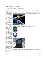
9. "Bluetooth" outline
(a) "Bluethooth" is a trademark owned by Bluetooth
SIG. Inc.
(b) "Bluetooth" is a new wireless connection technology
that uses the 2.4 GHz frequency band. This makes
it possible to connect a cellular phone ("Bluetooth"
compatible phone
*1
) to the radio and navigation
assembly (the "Bluetooth" system is built in), and
use the handsfree function of the cellular phone,
even if it is in a pocket or bag. As a result, it is not
necessary to use a connector attached directly to
the cellular phone.
*1: Some versions of "Bluetooth" compatible cellular
phones may not function.
HINT:
The communication performance of "Bluetooth"
may vary depending on obstructions or radio wave
conditions between communication devices,
electromagnetic radiation, communication device
sensitivity, or antenna capacity.
E100921
Example:
Radio and Navigation Assembly
(Built-in “Bluetooth” receiver antenna)
Cellular Phone (”Bluetooth” type)
Cellular Tower
E121227E02
NS–16
NAVIGATION – NAVIGATION SYSTEM
NS
HOW TO PROCEED WITH
TROUBLESHOOTING
NEXT
(a) Ask the customer about symptoms and confirm
malfunctions.
HINT:
If the system cannot enter the diagnostic mode, inspect the
AVC-LAN and all the components that connect to the AVC-
LAN for short circuits and repair or replace the problem part.
(a) Clear the DTCs and finish the diagnostic mode.
HINT:
The currently output DTCs may not indicate actual
malfunctions depending on the vehicle conditions.
NEXT
1
VEHICLE BROUGHT INTO A WORKSHOP
2
DIAGNOSTIC QUESTIONING AND SYMPTOM CONFIRMATION
THE SCREEN DISPLAYS NOTHING (GO TO
STEP 8, AND PROCEED TO "BLACK
SCREEN")
OTHER SYMPTOMS (GO TO STEP 3)
3
CONFIRM THE SYSTEM NORMAL CONDITION
APPLICABLE (THIS IS NOT A
MALFUNCTION)
NOT APPLICABLE (GO TO STEP 4)
4
CHECK DTC
A CODE IS OUTPUT (GO TO STEP 5)
A CODE IS NOT OUTPUT (GO TO STEP 8)
5
DTC CLEAR
NAVIGATION – NAVIGATION SYSTEM
NS–17
NS
HINT:
• If the system cannot enter the diagnostic mode, inspect
the AVC-LAN and all the components that connect to the
AVC-LAN for short circuits.
• Even if the malfunction symptom is not confirmed, check
for diagnostic trouble codes. This is because the system
stores past diagnostic trouble codes.
• Refer to the detailed description on the diagnostic screen
as necessary (See page NS-30).
• Check the diagnostic trouble code and inspect the area
the code indicates.
(a) Find the output code in the diagnostic trouble code chart
(See page NS-52).
NEXT
(a) Find the applicable symptom code in the problem
symptoms table (See page NS-41).
HINT:
If the symptom does not recur and no code is output,
perform the symptom reproduction method (See page
IN-40).
NEXT
(a) Adjust, repair, or replace as necessary.
6
RECHECK DTC
A CODE IS OUTPUT (GO TO STEP 7)
A CODE IS NOT OUTPUT (GO TO STEP 8)
7
DIAGNOSTIC TROUBLE CODE CHART
GO TO STEP 10
8
PROBLEM SYMPTOMS TABLE
THERE IS AN APPLICABLE SYMPTOM
CODE IN THE TABLE (GO TO STEP 10)
THERE IS NO APPLICABLE SYMPTOM
CODE IN THE TABLE (GO TO STEP 9)
9
CHECK THE ECU TERMINAL ARRANGEMENT BASED ON THE MALFUNCTION
SYMPTOM
10
CHECK THE CIRCUIT
NS–18
NAVIGATION – NAVIGATION SYSTEM
NS
NEXT
HINT:
After deleting the DTCs, recheck for diagnostic trouble codes.
NEXT
NEXT
11
RECHECK THE DIAGNOSTIC TROUBLE CODE
12
PERFORM CONFIRMATION TEST
END
NAVIGATION – NAVIGATION SYSTEM
NS–19
NS
IDENTIFICATION OF NOISE SOURCE
1. Radio Description
(a) Radio frequency band
(1) Radio broadcasts use the radio frequency bands
shown in the table below.
(b) Service area
(1) The service areas of AM and FM broadcasts are
vastly different. Sometimes an AM broadcast
can be received very clearly but an FM stereo
cannot. FM stereo has the smallest service area,
and is prone to pick up static and other types of
interference such as noise.
(c) Radio reception problems
HINT:
In addition to static, other problems such as
"phasing", "multipath", and "fade out" exist. These
problems are not caused by electrical noise, but by
the radio signal propagation method itself.
(1) Phasing
AM broadcasts are susceptible to electrical
interference and another kind of interference
called phasing. Occurring only at night, phasing
is the interference created when a vehicle
receives 2 radio wave signals from the same
transmitter. One signal is reflected off the
ionosphere and the other signal is received
directly from the transmitter.
Frequency
30 kHz
30 MHz
30 MHz
300 kHz
300 MHz
Designation
Radio Wave
Modulation
LF
MF
HF
VHF
AM
FM
Frequency modulation
Amplitude modulation
LF: Low Frequency
VHF: Very High Frequency
HF: High Frequency
MF: Medium Frequency
E108734E01
FM (Stereo)
FM (Monaural)
AM
E108735E01
Phasing
Ionosphere
I100011E02
NS–20
NAVIGATION – NAVIGATION SYSTEM
NS
(2) Multipath
Multipath is a type of interference created when
a vehicle receives 2 radio wave signals from the
same transmitter. One signal is reflected off
buildings or mountains and the other signal is
received directly from the transmitter.
(3) Fade out
Fade out is caused by objects (buildings,
mountains, and other such large obstacles) that
deflect away part of a signal, resulting in a
weaker signal when the object is between the
transmitter and vehicle. High frequency radio
waves, such as FM broadcasts, are easily
deflected by obstructions. Low frequency radio
waves, such as AM broadcasts, are much more
difficult to deflect.
(d) Noise problem
Technicians must have a clear understanding about
each customer's noise complaint. Use the following
table to diagnose noise problems.
HINT:
If the noise does not match the examples above, refer to the
descriptions about phasing and multipath.
Multipath
I100012E02
Fade Out
I100013E02
Radio Frequency Noise Occurrence Condition Presumable Cause
AM Noise occurs in a specified area Foreign noise
AM Noise occurs when listening to an intermittent broadcast
An identical program transmitted from
multiple towers can cause noise where the
signals overlap
AM Noise occurs only at night Music beat from a distant broadcast
FM Noise occurs while driving in a specified area
Multipath or phasing noise resulting from a
change in FM frequency
NAVIGATION – NAVIGATION SYSTEM
NS–21
NS
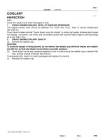
SYSTEM NORMAL CONDITION CHECK
1. CHECK NORMAL CONDITION
(a) If the symptom is applicable to any of the following,
it is intended behavior, and not a malfunction.
(b) The following symptoms are not a malfunction, but
are caused by errors inherent in the GPS, gyro
sensor, speed sensor, and radio and navigation
assembly.
(1) The current position mark may be displayed on a
nearby parallel road.
(2) Immediately after a fork in the road, the current
vehicle position mark may be displayed on the
wrong road.
(3) When the vehicle turns right or left at an
intersection, the current vehicle position mark
may be displayed on a nearby parallel road.
Symptom Answer
A longer route than expected is chosen.
Depending on the road conditions, the radio and navigation assembly
may determine that a longer route is quicker.
Even when distance priority is high, the shortest route is not shown. Some paths may not be advised due to safety concerns.
When the vehicle is put into motion immediately after the engine
starts, the navigation system deviates from the actual position.
If the vehicle starts before the navigation system activates, the system
may not react.
When running on certain types of roads, especially new roads, the
vehicle position deviates from the actual position.
When the vehicle is driving on new roads not available on the map
disc, the system attempts to match it to another nearby road, causing
the position mark to deviate.
I100066
I100067
I100068
NS–22
NAVIGATION – NAVIGATION SYSTEM
NS
(4) When the vehicle is carried, such as on a ferry,
and the vehicle itself is not running, the current
vehicle position mark may be displayed in the
position where the vehicle was until a
measurement can be performed by GPS.
(5) When the vehicle runs on a steep hill, the
current vehicle position mark may deviate from
the correct position.
(6) When the vehicle makes a continuous turn of
360, 720, 1,080, etc. degrees, the current
vehicle position mark may deviate from the
correct position.
(7) When the vehicle moves erratically, such as
constant lane changes, the current vehicle
position mark may deviate from the correct
position.
(8) When the ignition switch is turned on (ACC or
IG) on a turntable before parking, the current
vehicle position mark may not point in the
correct direction. The same will occur when the
vehicle comes out of parking.
I100069
I100070
I100071
I100072
I038146
NAVIGATION – NAVIGATION SYSTEM
NS–23
NS
(9) When the vehicle runs on a snowy road or a
mountain path with the chains installed or using
a spare tire, the current vehicle position mark
may deviate from the correct position.
(10)When a tire is changed, the current vehicle
position mark may deviate from the correct
position.
HINT:
• Diameter of the tire may change, causing a
speed sensor error.
• Performing the "tire change" in calibration
mode will allow the system to correct the
current vehicle position faster.
I100074
I100075
NS–24
NAVIGATION – NAVIGATION SYSTEM
NS
DISPLAY CHECK MODE
HINT:
• This mode checks the color display on the display.
• Illustrations may differ from the actual vehicle depending
on the device settings and options. Therefore, some
detailed areas may not be shown exactly the same as on
the actual vehicle.
1. ENTER DIAGNOSTIC MODE (See page NS-46)
2. DISPLAY CHECK
(a) Select "Display Check" from the "Diagnosis MENU"
screen.
3. COLOR BAR CHECK
(a) Select "Color Bar Check" from the "Display Check"
screen.
(b) Select a color bar from the "Color Bar Check Mode"
screen.
(c) Check the display color.
HINT:
• The entire screen turns to the color or stripe
selected.
• Touching the display will return to the "Color Bar
Check" screen.
E120055E02
E120053E07
E120102
NAVIGATION – NAVIGATION SYSTEM
NS–25
NS
4. TOUCH SWITCH CHECK
(a) Select "Touch Switch Check" from the "Display
Check" screen.
(b) Touch the display anywhere in the open area to
perform the check when the "Touch Switch Check"
screen is displayed.
HINT:
• A "+" mark is displayed where the display is
touched.
• The "+" mark remains on the display even after
the finger is removed.
5. PANEL SWITCH CHECK
(a) Select "Panel Switch Check" from the "Display
Check" screen.
(b) Operate each switch and check that the switch
name and condition are correctly displayed.
E125809E02
E120103
E125809E03
*2
*1
*3
I100041E07
Display Contents
Push switch name/*1
• Name of the pressed switch is displayed.
• If more than one switch is pressed, "MULTIPLE" is displayed.
Rotary switch name/*2 Name of the rotary switch is displayed.
Rotary switch direction/*3 Direction of the rotary switch is displayed.