Toyota camry 2006 2011 seat belt hệ thống đai an toàn trên toyota camry đời 2006 2011
Bạn đang xem bản rút gọn của tài liệu. Xem và tải ngay bản đầy đủ của tài liệu tại đây (4.14 MB, 71 trang )
SEAT BELT – SEAT BELT WARNING SYSTEM
SB–1
SB
RESTRAINTSSEAT BELT
SEAT BELT WARNING SYSTEM
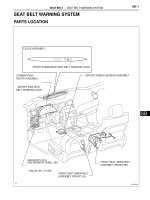
PARTS LOCATION
CLOCK ASSEMBLY:
FRONT PASSENGER SEAT BELT WARNING LIGHT
- DRIVER SIDE SEAT
BELT WARNING LIGHT
COMBINATION
METER ASSEMBLY
(INSTRUMENT PANEL J/B)
MAIN BODY ECU
CENTER AIRBAG SENSOR ASSEMBLY
FRONT SEAT INNER BELT
ASSEMBLY (FRONT RH)
FRONT SEAT INNER BELT
ASSEMBLY (FRONT LH)
- GAUGE NO. 2 FUSE
B137076E01
SB–2
SEAT BELT – SEAT BELT WARNING SYSTEM
SB
SYSTEM DIAGRAM
Front Seat Inner
Belt RH
Front Seat Inner
Belt LH
Occupant
Detection ECU
Center Airbag
Sensor Assembly
Combination
Meter Assembly
Road Sensor FL
Road Sensor FR
Road Sensor RL
SV3
SIG3
SGD3
FSR+
FSR-
FSP+
FSP-
CANH
CANL
DBE+
DBE-
CANH
9
P/BE
CANL
19
: CAN
10
PBEW
GND1
IG
3
SV4
SIG4
SGD4
SV2
SIG2
SGD2
SV1
SIG1
SGD1
BSW
BGN
Road Sensor RRClock Assembly
F3
F1
from GAUGE
No. 2 fuse
B137075E01
SEAT BELT – SEAT BELT WARNING SYSTEM
SB–3
SB
SYSTEM DESCRIPTION
1. Driver seat belt warning light
(a) When the driver seat belt is not fastened with the
ignition switch on (IG), the driver seat belt warning
light on the combination meter assembly comes on
to inform the driver. The center airbag assembly
detects the driver seat belt status and sends signals
to the combination meter assembly using CAN.
2. Passenger seat belt warning
(a) When the passenger seat belt is not fastened with
the ignition switch on (IG) and the passenger seat
occupied, check that the passenger seat belt
warning light on the clock display blinks. The
combination meter assembly displays the
passenger seat belt status and whether the
passenger seat is occupied.
SB–4
SEAT BELT – SEAT BELT WARNING SYSTEM
SB
HOW TO PROCEED WITH
TROUBLESHOOTING
HINT:
• Use the following procedures to troubleshoot the seat belt
warning system.
• *: Use the intelligent tester.
NEXT
Standard voltage:
11 to 14 V
If the voltage is below 11 V, recharge or replace the battery
before proceeding to the next step.
NEXT
(a) Use the intelligent tester to check if the CAN
Communication System (CAN) is functioning normally.
Result
B
A
HINT:
See page SB-4.
NEXT
(a) DATA LIST / ACTIVE TEST (See page SB-7)
(b) Terminals of ECU (See page SB-4)
(c) On-vehicle Inspection (See page SB-7)
NEXT
1
VEHICLE BROUGHT TO WORKSHOP
2
INSPECT BATTERY VOLTAGE
3
CHECK COMMUNICATION FUNCTION OF CAN COMMUNICATION SYSTEM (CAN)*
Result Proceed to
CAN DTC is not output A
CAN DTC is output B
GO TO CAN COMMUNICATION SYSTEM
4
PROBLEM SYMPTOMS TABLE
5
OVERALL ANALYSIS AND TROUBLESHOOTING*
SEAT BELT – SEAT BELT WARNING SYSTEM
SB–5
SB
NEXT
NEXT
6
REPAIR OR REPLACE
7
CONFIRMATION TEST
END
SB–6
SEAT BELT – SEAT BELT WARNING SYSTEM
SB
PROBLEM SYMPTOMS TABLE
SEAT BELT WARNING SYSTEM
Symptom Suspected area See page
Driver side seat belt warning light does not operate
1. Front seat inner belt LH SB-9
2. Center airbag sensor assembly SB-9
3. Combination meter assembly SB-9
4. Wire harness SB-9
Front passenger seat belt warning light does not
operate
1. Front seat inner belt RH SB-11
2. Occupant detection ECU SB-11
3. Road sensor SB-11
4. Center airbag sensor assembly SB-11
5. Combination meter assembly SB-11
6. Clock assembly SB-11
7. Wire harness SB-11
SEAT BELT – SEAT BELT WARNING SYSTEM
SB–7
SB
TERMINALS OF ECU
1. CLOCK ASSEMBLY
Standard voltage
Standard resistance
Terminal No. (Symbols) Terminal Description Condition Specified Condition
F3-3 (IG) - Body ground Power supply Ignition switch OFF → ON (IG) Below 1 V → 10 to 14 V
Terminal No. (Symbols) Terminal Description Condition Specified Condition
F3-10 (PBEW) - Body ground Passenger seat belt signal
The passenger seat is
occupied, seat belt is fastened
→ unfastened
Below 1 Ω → 10 kΩ or higher
F3-19 (GND1) - Body ground Ground Always Below 1 Ω
F3
B140734E01
SB–8
SEAT BELT – SEAT BELT WARNING SYSTEM
SB
DIAGNOSIS SYSTEM
1. DESCRIPTION
(a) The seat belt warning system data can be read from
the Data Link Connector 3 (DLC3) of the vehicle.
When the system seems to be malfunctioning, use
the intelligent tester to check for malfunctions and
perform repairs.
2. CHECK DLC3
(a) The ECU uses ISO 15765-4 communication. The
terminal arrangement of the DLC3 complies with
SAE J 1962 and matches the ISO 15765-4 format.
NOTICE:
*: Before measuring the resistance, leave the
vehicle as is for at least 1 minute and do not
operate the ignition switch, any other switches
or the door.
CG
SG
BAT
SIL
CANH
CANL
H100769E16
Intelligent Tester
DLC3
C131977E01
Symbols (Terminals No.) Terminal Description Condition Specified Condition
SIL (7) - SG (5) Bus "+" line During transmission Pulse generation
CG (4) - Body ground Chassis ground Always Below 1 Ω
SG (5) - Body ground Signal ground Always Below 1 Ω
BAT (16) - Body ground Battery positive Always 10 to 14 V
CANH (6) - CANL (14) CAN bus line Ignition switch OFF* 54 to 69 Ω
CANH (6) - CG (4) HIGH-level CAN bus line Ignition switch OFF* 200 Ω or more
CANL (14) - CG (4) LOW-level CAN bus line Ignition switch OFF* 200 Ω or more
CANH (6) - BAT (16) HIGH-level CAN bus line Ignition switch OFF* 6 kΩ or more
CANL (14) - BAT (16) LOW-level CAN bus line Ignition switch OFF* 6 kΩ or more
SEAT BELT – SEAT BELT WARNING SYSTEM
SB–9
SB
If the result is not as specified, the DLC3 may have
a malfunction. Repair or replace the harness and
connector.
HINT:
Connect the cable of the intelligent tester to the
DLC3, turn the ignition switch on (IG) and attempt to
use the tester. If the display indicates that a
communication error has occurred, there is a
problem either with the vehicle or with the tester.
• If communication is normal when the tester is
connected to another vehicle, inspect the DLC3
of the original vehicle.
• If communication is still not possible when the
tester is connected to another vehicle, the
problem may be in the tester itself. Consult the
Service Department listed in the tester's
instruction manual.
SB–10
SEAT BELT – SEAT BELT WARNING SYSTEM
SB
DATA LIST / ACTIVE TEST
1. ACTIVE TEST
Performing the ACTIVE TEST using the intelligent tester
allows the meters, indicators and so on to operate
without removing any parts. Performing the ACTIVE
TEST as the first step in troubleshooting is one way to
shorten labor time.
(a) Connect the intelligent tester to the DLC3.
(b) Turn the ignition switch on (IG).
(c) From the display on the tester, select the "ACTIVE
TEST".
METER:
Item Test Details Diagnostic Note
D-BELT REMIND D-SEAT BELT indicator light (OFF/ON) Confirm that the vehicle is stopped with the engine idling
P-BELT REMIND P-SEAT BELT indicator light (OFF/ON) Confirm that the vehicle is stopped with the engine idling
SEAT BELT – SEAT BELT WARNING SYSTEM
SB–11
SB
ON-VEHICLE INSPECTION
1. INSPECT DRIVER SIDE SEAT BELT WARNING
(a) Turn the ignition switch on (IG).
(b) When the driver seat belt is not fastened, check that
the driver seat belt warning light on the combination
meter blinks.
(c) When the driver seat belt is fastened, check that the
driver seat belt warning light on the combination
meter is off.
2. INSPECT PASSENGER SIDE SEAT BELT WARNING
(a) Turn the ignition switch on (IG).
(b) When the front passenger seat belt is not fastened
with the passenger seat occupied, check that the
front passenger seat belt warning light on the clock
display blinks.
(c) When the front passenger seat belt is fastened with
the passenger seat occupied, check that the front
passenger seat belt warning light on the clock
display is off.
3. INSPECT SEAT BELT WARNING BUZZER
HINT:
If the buzzer does not sound, the buzzer cancel setting
may be set to ON.
(a) Turn the ignition switch on (IG).
(b) When the vehicle is driven at approximately 25 km/h
(16 mph) or more while the driver or front passenger
seat belt is not being fastened, check that the
buzzer in the combination meter assembly sounds
at an interval of 1.2 seconds for 30 seconds.
(c) Check that the buzzer sounds at an interval of 0.4
seconds for 90 seconds.
(d) Check that the buzzer stops 2 minutes after the
buzzer starts sounding.
(e) After the buzzer has stopped, turn the ignition
switch off and then start the engine again. Drive the
vehicle at approximately 25 km/h (16 mph) or more
while the driver or front passenger seat belt is not
being fastened, and then check that the buzzer
sounds again.
(f) After the buzzer has stopped, fasten the driver and
front passenger seat belts. Drive the vehicle at
approximately 25 km/h (16 mph) or more and
unfasten the driver or front passenger seat belt, and
then check that the buzzer sounds again.
(g) After the buzzer has stopped, move the shift lever to
the R position, and then move it to the D position.
Drive the vehicle at approximately 25 km/h (16 mph)
or more, and then check that the buzzer sounds
again.
SB–12
SEAT BELT – SEAT BELT WARNING SYSTEM
SB
DESCRIPTION
When the ignition switch is on (IG), the center airbag sensor assembly transmits front seat inner belt state
signals to the combination meter assembly through CAN. If the driver seat belt is not fastened, the
combination meter assembly blinks the driver seat belt warning light. If the seat belt is fastened, the
warning light goes off.
NOTICE:
The seat belt warning system uses CAN. Before troubleshooting the seat belt warning system,
perform "COMMUNICATION FUNCTION CHECK" by following "HOW TO PROCEED WITH
TROUBLESHOOTING" to confirm that the communication systems are normal.
WIRING DIAGRAM
INSPECTION PROCEDURE
(a) Check for DTCs.
Result
A
B
Driver Side Seat Belt Warning Light does not Operate
1
CHECK FOR DTCs
Combination Meter
Assembly
Center Airbag
Sensor Assembly
Front Seat Inner
Belt Assembly LH
from GAUGE No. 2 fuse
DBE+
DBE-
CANH
CANL
: CAN
18
13
22
11
12
1
3
17
12
E2
CANH
F1 N3
CANL
13
IG+
B137085E01
Result Proceed to
Output DTC (CAN communication) A
Output DTC (Airbag system) B
No output DTC C
GO TO CAN COMMUNICATION SYSTEM
GO TO AIRBAG SYSTEM
SEAT BELT – SEAT BELT WARNING SYSTEM
SB–13
SB
C
(a) Operate the intelligent tester according to the steps on
the display and select "ACTIVE TEST".
METER
OK:
Switch condition (ON/OFF) can be switched by
"ACTIVE TEST".
NG
OK
2
PERFORM ACTIVE TEST BY INTELLIGENT TESTER
Item Test Details Diagnostic Note
D-BELT REMIND D-SEAT BELT indicator light (OFF/ON)
Confirm that the vehicle is stopped with
the engine idling
REPLACE COMBINATION METER
ASSEMBLY
END
SB–14
SEAT BELT – SEAT BELT WARNING SYSTEM
SB
DESCRIPTION
The occupant detection ECU detects the state of the front seat inner belt assembly RH and road sensor
when the front passenger seat is occupied with the ignition switch on (IG). If the front passenger seat belt
is not fastened, the front seat belt warning light on the clock display blinks. If the seat belt is fastened, the
warning light goes off.
WIRING DIAGRAM
Front Passenger Side Seat Belt Warning Light Malfunction
Front Seat Inner
Belt RH
Occupant
Detection ECU
Center Airbag
Sensor Assembly
Combination
Meter Assembly
Road Sensor FL
Road Sensor FR
Road Sensor RL
SV3
SIG3
SGD3
FSR+
FSR-
FSP+
FSP-
CANH
CANL
CANH
9
P/SB
CANL
19
10
PBEW
GND1
IG
3
SV4
: CAN
SIG4
SGD4
SV2
SIG2
SGD2
SV1
SIG1
SGD1
BSW
BGN
Road Sensor RR
Clock Assembly
F3
F1
from GAUGE
No. 2 fuse
B140735E01
SEAT BELT – SEAT BELT WARNING SYSTEM
SB–15
SB
INSPECTION PROCEDURE
(a) Check for DTCs.
Result
B
C
A
(a) Disconnect the clock assembly connector.
(b) Measure the voltage and resistance according to the
value(s) in the table below.
Standard voltage
Standard resistance
NG
OK
(a) Disconnect the clock assembly connector.
(b) Apply battery voltage to the connector according to the
table below.
Standard
NG
1
CHECK FOR DTCs
Result Proceed to
No output DTC A
Output DTC (CAN communication) B
Output DTC (Occupant detection) C
GO TO CAN COMMUNICATION SYSTEM
GO TO OCCUPANT CLASSIFICATION
SYSTEM
2
CHECK WIRE HARNESS (BATTERY POSITIVE AND BODY GROUND)
F3
B137073E01
Tester Connection Condition Specified Condition
F3-3 (IG) - Body ground Ignition switch on (IG) 10 to 14 V
Tester Connection Condition Specified Condition
F3-19 (GND1) - Body
ground
Always Below 1 Ω
REPAIR OR REPLACE GAUGE NO. 2 FUSE,
HARNESS OR CONNECTOR
3
CHECK CLOCK ASSEMBLY
F3
B137074E01
Condition Specified Condition
Battery positive (+) → Terminal 3 (IG)
Battery negative (-) → Terminal 10
(PBEW), 19 (GND1)
Lights up (Seat belt warning light)
REPLACE CLOCK ASSEMBLY
SB–16
SEAT BELT – SEAT BELT WARNING SYSTEM
SB
OK
(a) Disconnect the combination meter assembly and clock
assembly connectors.
(b) Measure the resistance according to the value(s) in the
table below.
Standard resistance
NG
OK
4
CHECK WIRE HARNESS (CLOCK ASSEMBLY - COMBINATION METER ASSEMBLY)
Clock Assembly:
F3
P/SB
PBEW
Combination Meter Assembly:
F1
B137077E01
Tester Connection Condition Specified Condition
F1-9 (P/SB) - F3-10
(PBEW)
Always Below 1 Ω
F1-9 (P/SB) - Body
ground
Always 10 kΩ or higher
REPAIR OR REPLACE HARNESS OR
CONNECTOR
REPLACE COMBINATION METER ASSEMBLY
SB–14
SEAT BELT – FRONT SEAT INNER BELT ASSEMBLY
SB
RESTRAINTSSEAT BELT
FRONT SEAT INNER BELT ASSEMBLY
COMPONENTS
N*m (kgf*cm, ft.*lbf)
: Specified torque
37 (377, 27)
FRONT SEAT HEADREST ASSEMBLY
FRONT SEAT INNER
BELT ASSEMBLY
FRONT SEAT HEADREST ASSEMBLY
FRONT SEAT INNER
BELT ASSEMBLY
37 (377, 27)
37 (377, 27)
37 (377, 27)
for Manual Seat:
for Power Seat:
42 (428, 31)
42 (428, 31)
FRONT SEAT ASSEMBLY
FRONT SEAT ASSEMBLY
INNER SEAT TRACK
BRACKET COVER
INNER SEAT TRACK
BRACKET COVER
SEAT TRACK COVER
SEAT TRACK COVER
B132031E01
SEAT BELT – FRONT SEAT INNER BELT ASSEMBLY
SB–15
SB
REMOVAL
1. DISCONNECT CABLE FROM NEGATIVE BATTERY
TERMINAL (for Manual Seat)
CAUTION:
Wait for 90 seconds after disconnecting the cable to
prevent airbag deployment (See page RS-1).
2. REMOVE FRONT SEAT HEADREST ASSEMBLY
3. REMOVE SEAT TRACK COVER (for Manual Seat)
(See page SE-16)
4. REMOVE INNER SEAT TRACK BRACKET COVER
(for Manual Seat) (See page SE-16)
5. REMOVE FRONT SEAT ASSEMBLY (for Manual Seat)
(See page SE-16)
6. REMOVE SEAT TRACK COVER (for Power Seat) (See
page SE-30)
7. REMOVE INNER SEAT TRACK BRACKET COVER
(for Power Seat) (See page SE-30)
8. REMOVE FRONT SEAT ASSEMBLY (for Power Seat)
(See page SE-30)
9. REMOVE FRONT SEAT INNER BELT ASSEMBLY (for
Manual Seat)
(a) for Driver seat:
(1) Disconnect the connectors and disengage the
4 clamps.
(b) for Passenger seat:
(1) Disconnect the connector and disengage the 3
clamps.
for Driver seat:
for Passenger seat:
Clamp
B132032E02
SB–16
SEAT BELT – FRONT SEAT INNER BELT ASSEMBLY
SB
(c) Remove the nut and front seat inner belt assembly.
10. REMOVE FRONT SEAT INNER BELT ASSEMBLY (for
Power Seat)
(a) for Driver seat:
(1) Disconnect the connectors and disengage the
4 clamps.
(b) for Passenger seat:
(1) Disconnect the connector and disengage the 3
clamps.
(c) Remove the nut and front seat inner belt assembly.
INSTALLATION
1. INSTALL FRONT SEAT INNER BELT ASSEMBLY (for
Manual Seat)
(a) Install the front seat inner belt assembly with the
nut.
Torque: 42 N*m (428 kgf*cm, 31 ft.*lbf)
NOTICE:
Do not allow the anchor part of the front seat
inner belt assembly to overlap the protruding
parts of the front seat adjuster.
B132034
for Driver seat:
for Passenger seat:
Clamp
B132033E01
B132034
Protruding Parts
B132035E01
SEAT BELT – FRONT SEAT INNER BELT ASSEMBLY
SB–17
SB
(b) for Driver seat:
(1) Connect the connectors and engage the 4
clamps.
(c) for Passenger seat:
(1) Connect the connector and engage the 3
clamps.
2. INSTALL FRONT SEAT INNER BELT ASSEMBLY (for
Power Seat)
(a) Install the front seat inner belt assembly with the
nut.
Torque: 42 N*m (428 kgf*cm, 31 ft.*lbf)
NOTICE:
Do not allow the anchor part of the front seat
inner belt assembly to overlap the protruding
parts of the front seat adjuster.
(b) for Driver seat:
(1) Connect the connectors and engage the 4
clamps.
(c) for Passenger seat:
(1) Connect the connector and engage the 3
clamps.
3. INSTALL FRONT SEAT ASSEMBLY (for Manual Seat)
(See page SE-24)
4. INSTALL INNER SEAT TRACK BRACKET COVER (for
Manual Seat) (See page SE-25)
5. INSTALL SEAT TRACK COVER (for Manual Seat)
(See page SE-25)
6. INSTALL FRONT SEAT ASSEMBLY (for Power Seat)
(See page SE-41)
7. INSTALL INNER SEAT TRACK BRACKET COVER (for
Power Seat) (See page SE-42)
8. INSTALL SEAT TRACK COVER (for Power Seat) (See
page SE-42)
for Driver seat:
for Passenger seat:
Clamp
B132032E02
Protruding Parts
B132035E01
for Driver seat:
for Passenger seat:
Clamp
B132033E01
SB–18
SEAT BELT – FRONT SEAT INNER BELT ASSEMBLY
SB
9. INSTALL FRONT SEAT HEADREST ASSEMBLY
10. CONNECT CABLE TO NEGATIVE BATTERY
TERMINAL (for Manual Seat)
11. PERFORM ZERO POINT CALIBRATION AND
SENSITIVITY CHECK (for Front Passenger Seat)
(See page RS-242)
12. INSPECT SLIDE ADJUSTER LOCK (for Manual Seat)
13. INSPECT FRONT SEAT ASSEMBLY (for Power Seat)
(See page SE-42)
14. INSPECT SRS WARNING LIGHT
(See page RS-32)
SEAT BELT – FRONT SEAT OUTER BELT ASSEMBLY
SB–19
SB
RESTRAINTSSEAT BELT
FRONT SEAT OUTER BELT ASSEMBLY
COMPONENTS
N*m (kgf*cm, ft.*lbf)
: Specified torque
42 (428, 31)
7.5 (77, 66 in.*lbf)
42 (428, 31)
42 (428, 31)
42 (428, 31)
42 (428, 31)
FRONT DOOR OPENING
TRIM WEATHERSTRIP
FRONT DOOR SCUFF PLATE
FRONT SEAT OUTER BELT ASSEMBLY
FRONT SHOULDER BELT ANCHOR
ADJUSTER ASSEMBLY
LAP BELT OUTER ANCHOR COVER
LOWER CENTER PILLAR GARNISH
REAR DOOR OPENING
TRIM WEATHERSTRIP
REAR DOOR SCUFF PLATE
UPPER CENTER PILLAR GARNISH
B132005E01
SB–20
SEAT BELT – FRONT SEAT OUTER BELT ASSEMBLY
SB
REMOVAL
1. DISCONNECT CABLE FROM NEGATIVE BATTERY
TERMINAL
CAUTION:
Wait for 90 seconds after disconnecting the cable to
prevent airbag deployment (See page RS-1).
2. REMOVE LAP BELT OUTER ANCHOR COVER
(a) Disengage the 3 claws and remove the lap belt
outer anchor cover.
3. DISCONNECT FRONT SEAT OUTER BELT
ASSEMBLY
(a) Remove the bolt and disconnect the floor end of the
front seat outer belt assembly.
4. REMOVE FRONT DOOR SCUFF PLATE (See page IR-
24)
5. REMOVE FRONT DOOR OPENING TRIM
WEATHERSTRIP
6. REMOVE REAR DOOR SCUFF PLATE (See page IR-
24)
7. REMOVE REAR DOOR OPENING TRIM
WEATHERSTRIP
8. REMOVE LOWER CENTER PILLAR GARNISH (See
page IR-25)
9. REMOVE UPPER CENTER PILLAR GARNISH (See
page IR-26)
10. DISCONNECT FRONT SEAT OUTER BELT
ASSEMBLY
(a) Remove the nut and disconnect the shoulder
anchor of the front seat outer belt assembly.
B131995
B131996
B131997
SEAT BELT – FRONT SEAT OUTER BELT ASSEMBLY
SB–21
SB
11. REMOVE FRONT SHOULDER BELT ANCHOR
ADJUSTER ASSEMBLY
(a) Remove the 2 bolts and the front shoulder belt
anchor adjuster assembly.
12. REMOVE FRONT SEAT OUTER BELT ASSEMBLY
(a) Using a screwdriver, pull out the locking button in
the direction shown by the arrow to release the lock,
and disconnect the connector as shown in the
illustration.
HINT:
Tape the screwdriver tip before use.
(b) Remove the 2 bolts and the front seat outer belt
assembly.
INSTALLATION
1. INSTALL FRONT SEAT OUTER BELT ASSEMBLY
(a) Check the degree of tilt when the ELR begins to
lock.
(1) Check that the belt does not lock at less than
15 degrees of tilt in any direction but locks at
over 45 degrees of tilt while gently pulling the
belt.
NOTICE:
Do not disassemble the retractor.
(b) Temporarily install the front seat outer belt assembly
with the 2 bolts.
(c) Fully tighten the upper side bolt first, then the lower
side bolt to install the front seat outer belt assembly.
Torque: For upper bolt
7.5 N*m (77 kgf*cm, 66 in.*lbf)
For lower bolt
42 N*m (428 kgf*cm, 31 ft.*lbf)
B132001
B132002
B131998
45°
B132004E01
(1)
(2)
B131998E01
SB–22
SEAT BELT – FRONT SEAT OUTER BELT ASSEMBLY
SB
(d) Connect the connector and lock the locking button
as shown in the illustration.
NOTICE:
Securely lock the locking button.
2. INSTALL FRONT SHOULDER BELT ANCHOR
ADJUSTER ASSEMBLY
(a) Install the front shoulder belt anchor adjuster
assembly with the 2 bolts.
Torque: 42 N*m (428 kgf*cm, 31 ft.*lbf)
3. CONNECT FRONT SEAT OUTER BELT ASSEMBLY
(a) Connect the shoulder anchor of the front seat outer
belt assembly with the nut.
Torque: 42 N*m (428 kgf*cm, 31 ft.*lbf)
4. INSTALL UPPER CENTER PILLAR GARNISH (See
page IR-53)
5. INSTALL LOWER CENTER PILLAR GARNISH (See
page IR-53)
6. INSTALL REAR DOOR OPENING TRIM
WEATHERSTRIP (See page IR-55)
7. INSTALL REAR DOOR SCUFF PLATE (See page IR-
56)
8. INSTALL FRONT DOOR OPENING TRIM
WEATHERSTRIP (See page IR-54)
9. INSTALL FRONT DOOR SCUFF PLATE (See page IR-
54)
10. CONNECT FRONT SEAT OUTER BELT ASSEMBLY
(a) Install the floor end of the front seat outer belt
assembly with the bolt.
Torque: 42 N*m (428 kgf*cm, 31 ft.*lbf)
(b) Check if the ELR locks.
NOTICE:
The check should be performed with the outer
belt assembly installed.
(1) With the belt assembly installed, check that the
belt locks when it is pulled out quickly.
B132003
B132001
B131997
B131996