Toyota camry 2006 2011 theft deterrent hệ thống chống trộm trên toyota camry đời 2006 2011
Bạn đang xem bản rút gọn của tài liệu. Xem và tải ngay bản đầy đủ của tài liệu tại đây (2.66 MB, 88 trang )
THEFT DETERRENT – THEFT DETERRENT SYSTEM (w/ Smart Key System)
TD–1
TD
SECURITIESTHEFT DETERRENT
THEFT DETERRENT SYSTEM (w/ Smart Key System)
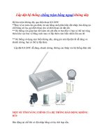
PARTS LOCATION
HEADLIGHT
HEADLIGHT
-
HAZARD WARNING LIGHT
HAZARD WARNING LIGHT
ENGINE HOOD LOCK ASSEMBLY
ENGINE ROOM R/B AND J/B
- S-HORN RELAY
- HORN RELAY
- H-LP(RL) RELAY
- H-LP(LL) RELAY
ENGINE HOOD COURTESY SWITCH
SECURITY HORN
ASSEMBLY
PERSONAL LIGHT ASSEMBLY
HIGH PITCHED
HORN
LOW PITCHED
HORN
B128403E01
TD–2
THEFT DETERRENT – THEFT DETERRENT SYSTEM (w/ Smart Key System)
TD
ENGINE SWITCH
CLOCK
SECURITY INDICATOR
MAIN BODY ECU
(INSTRUMENT PANEL J/B)
- TAIL RELAY
DLC3
CERTIFICATION ECU
TURN SIGNAL FLASHER
ASSEMBLY
B128406E01
THEFT DETERRENT – THEFT DETERRENT SYSTEM (w/ Smart Key System)
TD–3
TD
RH
LH
LH
LH
LH
RH
RH
RH
TAILLIGHT
-
TAILLIGHT
HAZARD WARNING
LIGHT
HAZARD
WARNING
LIGHT
LUGGAGE COMPARTMENT DOOR LOCK
LUGGAGE COMPARTMENT DOOR
COURTESY SWITCH
LUGGAGE COMPARTMENT
DOOR LOCK CYLINDER
FRONT DOOR LOCK
REAR DOOR LOCK
FRONT DOOR LOCK
REAR DOOR LOCK
FRONT DOOR COURTESY
SWITCH
REAR DOOR COURTESY
SWITCH
FRONT DOOR COURTESY
SWITCH
REAR DOOR COURTESY
SWITCH
B128405E01
TD–4
THEFT DETERRENT – THEFT DETERRENT SYSTEM (w/ Smart Key System)
TD
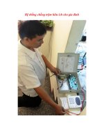
SYSTEM DIAGRAM
Security Horn
Certification
ECU
Main Body
ECU
Luggage Compartment
Door Lock Cylinder
DLC3
Engine Switch
Engine Hood Lock
Assembly (Engine
Hood Courtesy Switch)
Front Door Courtesy
Switch (LH, RH)
Rear Door Courtesy
Switch (LH, RH)
Front Door Lock
Position Switch
(LH, RH)
Rear Door Lock
Position Switch
(LH, RH)
Clock
Luggage Compartment
Door Lock Assembly
(Luggage Compartment
Door Courtesy Switch)
Turn Signal Flasher
Hazard Warning Light
Personal Light
Assembly
Head Relay
Tail Relay
Horn Relay
CAN
(Security Indicator)
B139449E01
THEFT DETERRENT – THEFT DETERRENT SYSTEM (w/ Smart Key System)
TD–5
TD
SYSTEM DESCRIPTION
1. OUTLINE OF THEFT DETERRENT SYSTEM
• The theft deterrent system will operate when
somebody attempts to forcibly enter the vehicle,
unlock any door or luggage compartment door, or
open the engine hood or the luggage compartment
door without using the key.
This system causes the lights to light up or blink and
the horns to sound in order to deter break-in and theft.
• The theft deterrent system has 2 modes; one is the
active arming mode (see ACTIVE ARMING MODE)
and the other is passive arming mode (see PASSIVE
ARMING MODE). The passive arming mode can be
switched ON/OFF using the specified method.
• Each mode has 4 states; a disarmed state, an arming
preparation state, an armed state and an alarm
sounding state.
(a) Disarmed state:
• The alarm function is not operating.
• The theft deterrent system is not operating.
(b) Arming preparation state:
• The time until the system goes into the armed
state.
• The theft deterrent system is not operating.
(c) Armed state:
• The theft deterrent system is operating.
(d) Alarm sounding state:
• Alarm function is operating.
Alarm time:
Approx. 60 sec.
Refer to table below for alarm method and time:
HINT:
If any of the doors are unlocked when the key is not
in the actuation area during the armed state, a
forced door lock signal will be output (see FORCED
DOOR LOCK CONTROL).
2. FUNCTION OF MAIN COMPONENT
Alarm Method
Headlight Blinking
Taillight Blinking
Hazard Warning Light Blinking
Interior Light Illuminating
Vehicle Horn
Sounding
(approx. 0.4 second cycles)
Security Horn
Sounding
(approx. 0.4 second cycles)
Alarm Time Approx. 60 sec.
Component Function
Security indicator Informs driver of theft deterrent system status.
Security horn Sounds when attempted brake-in or theft is detected.
Headlights Blink when attempted break-in or theft is detected.
Taillights Blink when attempted break-in or theft is detected.
Hazard warning lights Blinking when attempted break-in or theft is detected.
TD–6
THEFT DETERRENT – THEFT DETERRENT SYSTEM (w/ Smart Key System)
TD
3. ACTIVE ARMING MODE
HINT:
Active arming mode starts the alarm control immediately
after the doors are locked.
Interior light Lights up when attempted break-in or theft is detected.
Vehicle horns Sounds when attempted break-in or theft is detected.
Door courtesy light switch Detects door status (open or closed).
Door lock position switch Detects door status (locked or unlocked).
Engine hood courtesy switch Detects engine hood status (open or closed).
Luggage compartment door courtesy switch Detects luggage compartment door status (open or closed).
Luggage compartment door lock cylinder Detects luggage compartment door status (locked or unlocked).
Certification ECU
• Receives engine hood courtesy switch status.
• Sends operation signal to security indicator and security horn.
Component Function
THEFT DETERRENT – THEFT DETERRENT SYSTEM (w/ Smart Key System)
TD–7
TD
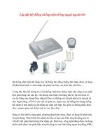
(a) Active arming mode:
This system activates as described in the diagram
below when one of items for each condition is met.
HINT:
• *1: Disarmed state 1 is the normal disarmed
state.
• *2: Disarmed state 2 is set from either the
disarmed state 1 or the arming preparation state.
Disarmed State 1
Disarmed State 2
Arming Preparation State
Armed State
Alarm Sounding State
Condition (3) Condition (1)
Condition (9)
Condition (10)
Condition (8)
Condition (4)
Condition (7)
Condition (7)
Condition (6)
Condition (5)
Condition (5)
Condition (2)
Condition (7)
Disarmed State
*1 *2
B144373E01
Condition Item
Condition (1)
In the disarmed state 1, when the key is not in the actuation area, the system state is switched if
one of the following conditions is met.
1. With all doors, engine hood and luggage compartment door closed, lock all doors by key
operation.
2. With all doors, engine hood and luggage compartment door closed, lock all doors by wireless
operation.
3. With engine hood and luggage compartment door closed and all doors locked with any door still
opened, close the open door.
TD–8
THEFT DETERRENT – THEFT DETERRENT SYSTEM (w/ Smart Key System)
TD
4. PASSIVE ARMING MODE
HINT:
• Passive arming mode starts the alarm control after
the key is out of the actuation area and doors are
closed.
• Passive arming mode can be switched ON/OFF by
the specified method.
• The alarm is initially set (when shipped from factory)
to active arming mode (not passive arming mode).
• During passive arming mode, the theft deterrent
system goes into the armed state even if the doors
are not locked.
• Detecting that the doors are unlocked does not set off
the alarm during passive arming mode.
• A forced door lock signal is not output during passive
arming mode (see FORCED DOOR LOCK
CONTROL).
• Although the theft deterrent system detects that the
doors are opened during passive arming mode, the
alarm will not go off immediately because an entry
delay time is set.
• If the condition (1) of active arming mode is met
during passive arming mode, the theft deterrent
system will switch to active arming mode.
Condition (2) After condition (1) is met, allow approx. 30 seconds to elapse.
Condition (3)
1. Unlock any door.
2. Open any door, engine hood, or luggage compartment door.
3. Turn the engine switch on (IG or ACC).
4. Reconnect battery.
Condition (4)
1. Open engine hood.
2. Open luggage compartment door.
3. Reconnect battery.
4. Open any door.
5. Unlock any door when all doors are locked without wireless operation.
Condition (5)
1. Unlock only driver's door or all doors by wireless operation.
2. Unlock only driver's door or all doors by key operation.
3. Turn the engine switch on (IG) and run the engine more than 2 seconds.
Condition (6) After approx. 60 seconds, alarm stops and system returns to armed state.
Condition (7)
1. Open the luggage compartment door by wireless operation.
2. Unlock the luggage compartment door by key operation.
Condition (8)
1. Close the engine hood when the luggage compartment door is closed.
2. Close the luggage compartment door when the engine hood is closed.
Condition (9)
1. Unlock any door.
2. Open any door.
3. Turn the engine switch from off to on (IG or ACC).
4. Reconnect the battery.
Condition (10)
In the disarmed state 1, when the key is not in the actuation area, the system state is switched if
one of the following conditions is met.
1. With all doors closed, and the engine hood or luggage compartment door is opened, lock all
doors by wireless operation.
2. With all doors closed, and the engine hood or luggage compartment door is opened, lock all
doors by key operation.
3. With the engine hood or luggage compartment door is opened and all doors locked with any
door still opened, close the open door.
Condition Item
THEFT DETERRENT – THEFT DETERRENT SYSTEM (w/ Smart Key System)
TD–9
TD
(a) Passive arming mode:
This system activates as described in the diagram
below when one of items for each condition is met.
HINT:
• *1: Disarmed state 1 is the normal disarmed
state.
• *2: Disarmed state 2 is set from either the
disarmed state 1 or the arming preparation state.
Disarmed State 1 Disarmed State 2
Arming Preparation State
Armed State
Alarm Sounding State
Condition (3)
Condition (3)
Condition (1)
Condition (2)
Condition (6)
Condition (8)
Condition (8)
Condition (9)
Condition (7)
Condition (7)
Condition (4)
Condition (5)
Disarmed State
*1 *2
B112143E02
Condition Item
Condition (1)
1. With any door open, turn the engine switch off.
2. With the engine switch off, open any door.
Condition (2) All doors, engine hood and luggage compartment door are closed.
Condition (3)
1. Unlock only driver's door or all doors by wireless operation.
2. Unlock only driver's door or all doors by key operation.
3. Reconnect battery.
4. Turn the engine switch on (IG or ACC).
TD–10
THEFT DETERRENT – THEFT DETERRENT SYSTEM (w/ Smart Key System)
TD
HINT:
*1: When any door is opened while all the doors are
closed during passive arming mode, the entry delay
time starts. If the switch condition (armed state →
disarmed state 1 or 2) is met during the entry delay
time, the theft deterrent system will return to
disarmed state 1 or 2. However, if the switch
condition for disarmed state 1 or 2 is not met, the
theft deterrent system will recognize it as a theft and
set off the alarm. Entry delay time of 0, 14 or 30 sec.
can be selected by the customizing function.
5. FORCED DOOR LOCK CONTROL
(a) The forced door lock control prevents the vehicle
from being tampered with. Immediately after a door
is unlocked (alarm starts), the door is forced to lock
by a forced door lock signal.
(1) Conditions that force the doors to lock:
When the key is not in the actuation area and
both of the following conditions are met.
• The theft deterrent system is in the alarm
sounding state of active arming mode.
• Any door is unlocked.
Condition (4) After condition (1) is met, allow approx. 30 seconds to elapse.
Condition (5)
1. Open any door.
2. Open engine hood.
3. Open luggage compartment door.
4. Unlock luggage compartment door.
Condition (6)
1. Open any door and allow entry delay time
*1
to elapse.
2. Open engine hood.
3. Open luggage compartment door.
4. Reconnect battery.
5. Turn the engine switch off. After 5 seconds or more elapsed, turn the engine switch on (IG).
Condition (7)
1. Unlock only driver's door or all doors by wireless operation.
2. Unlock only driver's door or all doors by key operation.
3. Turn the engine switch on (IG) and run the engine more than 2 seconds.
Condition (8)
1. Open luggage compartment door by wireless operation.
2. Unlock luggage compartment door by key operation.
Condition (9) After approx. 60 sec., alarm stops and system returns to armed state.
Condition Item
THEFT DETERRENT – THEFT DETERRENT SYSTEM (w/ Smart Key System)
TD–11
TD
6. ALARM MEMORY FUNCTION
(a) If the alarm is set off (tampering is detected) while
the theft deterrent system is armed, it will be
recorded by the alarm memory function. Whenever
the theft deterrent system is cancelled, the alarm
memory function causes the taillights to light up for
2 seconds in order to inform you that the alarm has
been set off.
(1) Conditions of the alarm memory function that
cause the taillights to light up:
When the theft deterrent system has entered
into the alarm sounding state (tampering has
been detected) even once, the taillights will light
up for 2 seconds if any of the following
conditions is met.
• Switched to the disarmed state from the
armed state during active arming mode.
• Switched to the disarmed state 1 from the
armed state during passive arming mode.
HINT:
Active arming mode: See ACTIVE ARMING
MODE.
Passive arming mode: See PASSIVE ARMING
MODE.
7. PANIC ALARM CONTROL
(a) The panic alarm control makes it possible to
voluntarily set off the panic alarm by pressing the
PANIC switch on the wireless transmitter.
(1) Conditions that cause the panic alarm control to
set off the panic alarm:
The panic alarm control sets off the panic alarm
by pressing the PANIC switch on the wireless
transmitter under the following conditions:
• The engine switch off.
• The theft deterrent system is not in the alarm
sounding state. (This condition is common
both to active arming mode and to passive
arming mode.)
(2) Conditions that cause the panic alarm control to
shut off the alarm:
The panic alarm control shuts off the panic alarm
when any of the following conditions is met
during panic alarm operation:
• The engine switch on (IG).
• The panic alarm switch is turned on again.
• Any of the switches on the wireless
transmitter (LOCK/UNLOCK or LUGGAGE
OPEN) is pressed.
• The panic alarm ends (approx. 60 sec. have
passed).
TD–12
THEFT DETERRENT – THEFT DETERRENT SYSTEM (w/ Smart Key System)
TD
• The theft deterrent system switches to the
alarm sounding state. Under this condition,
the theft deterrent system is controlling the
alarm rather than the panic alarm control. In
order to cancel this alarm, refer to the theft
deterrent system alarm sounding state
cancellation procedure. (This condition is
common both to active arming mode to
passive arming mode.)
HINT:
Active arming mode: See ACTIVE ARMING
MODE.
Passive arming mode: See PASSIVE ARMING
MODE.
8. SECURITY INDICATOR OUTPUT
(a) The certification ECU outputs a signal to light up the
security indicator, according to the state of the theft
deterrent system. However, some of the actual
lighting conditions of the security indicator are
different from the output signals of the certification
ECU.
Output:
Blinking cycle:
HINT:
• *: The above condition is common both to active
arming mode and to passive arming mode.
• When the immobiliser system is set, the security
indicator blinks during both the disarmed state
and the armed state, due to the output signals
from the immobiliser system.
State of Theft Deterrent System*
Security Indicator
Output Signals from certification ECU Actual Lighting Condition
Disarmed state 1, 2 OFF
OFF (Immobiliser system unset)
BLINKING (Immobiliser system set)
Arming preparation state ON ON
Armed state OFF BLINKING
Alarm sounding state ON ON
Time Security Indicator
0.2 sec. ON
1.8 sec. OFF
THEFT DETERRENT – THEFT DETERRENT SYSTEM (w/ Smart Key System)
TD–13
TD
HOW TO PROCEED WITH
TROUBLESHOOTING
HINT:
• Use this procedure to troubleshoot the theft deterrent
system.
• The intelligent tester should be used in step 3.
NEXT
(a) Interview the customer to confirm the trouble (See page
IN-45).
NEXT
(a) Use the intelligent tester to check for normal function of
the multiplex communication system.
(1) (ECU unconnected, communication line
malfunctioning) If no code is output, proceed to A.
(2) (ECU unconnected, communication line
malfunctioning) If any code is output, proceed to B.
B
A
NEXT
(a) If the fault is not listed in the problem symptoms table,
proceed to A.
(b) If the fault is listed in the problem symptoms table,
proceed to B.
B
A
(a) System description (See page TD-5)
1
VEHICLE BROUGHT TO WORKSHOP
2
CUSTOMER PROBLEM ANALYSIS
3
INSPECT COMMUNICATION FUNCTION OF CAN COMMUNICATION SYSTEM
Go To CAN COMMUNICATION SECTION
4
SYMPTOM SIMULATION
5
PROBLEM SYMPTOMS TABLE
Go to step 7
6
PERFORM TROUBLESHOOTING ACCORDING TO MALFUNCTION SYMPTOM
TD–14
THEFT DETERRENT – THEFT DETERRENT SYSTEM (w/ Smart Key System)
TD
(b) Terminals of ECU (See page TD-17)
NEXT
NEXT
7
ADJUST, REPAIR OR REPLACE
8
CONFIRMATION TEST
END
THEFT DETERRENT – THEFT DETERRENT SYSTEM (w/ Smart Key System)
TD–15
TD
CUSTOMIZE PARAMETERS
HINT:
The following items can be customized.
NOTICE:
• After confirming whether the items requested by the
customer are applicable or not for customization,
perform customizing operations.
• Be sure to record the current settings before
customization.
• When troubleshooting, make sure that the item in
question is not set to "OFF" as a result of
customization (Example: For the system, "the wireless
function does not operate", first check that the
wireless function is not set to "OFF", then perform
troubleshooting).
THEFT DETERRENT SYSTEM
DISPLAY (ITEM) DEFAULT CONTENTS SETTING
PASSIVE MODE
(Passive Arming Mode)
OFF
PASSIVE MODE is a function that switches theft deterrent
system from arming preparation state to armed state 30
seconds after key is not in the actuation area and all doors,
engine hood and luggage compartment door are closed, even
if doors are not locked by wireless or door key lock operation
In PASSIVE MODE, if you do not perform following operations
within 14 seconds after door is opened during armed state,
theft deterrent system will judge that condition as a theft and
switch to alarm sounding state
– Unlock any door by key or wireless operation
– Turn the engine switch on (IG)
– Open luggage compartment door by key or wireless
operation
ON/OFF
WARN BY HORN
(Warning by horn)
ON
Function that makes vehicle horn and theft deterrent horn be
able to be used as a warning device
ON/OFF
ENTRY DELAY
(Entry delay time)
14 s
Function that changes entry delay time (time before warning
starts) for PASSIVE MODE
0 s/14 s/30 s
TD–16
THEFT DETERRENT – THEFT DETERRENT SYSTEM (w/ Smart Key System)
TD
PROBLEM SYMPTOMS TABLE
HINT:
• Troubleshooting of the theft deterrent system is based on
the premise that the door lock control system and the
wireless door lock control system are operating normally.
Accordingly, before troubleshooting the theft deterrent
system, first make certain that the door lock control system
and the wireless door lock control system are operating
normally.
• The following is the troubleshooting procedure for the theft
deterrent system of a vehicle with the smart key system.
• Inspect the fuse and relay before investigating the
suspected areas shown in the table below.
Theft deterrent system:
Symptom Suspected area See page
Theft deterrent system cannot be set
1. Security indicator light circuit TD-34
2. ECU power source circuit TD-37
3. Door key lock / unlock switch circuit DL-53
4. Door courtesy switch circuit LI-52
5. Luggage compartment door courtesy switch circuit DL-44
6. Engine hood courtesy switch circuit TD-22
7. Replace certification ECU -
8. If the symptom(s) still occur after the above areas are
inspected and proved to be normal, replace the main body
ECU (Instrument panel J/B)
-
Security indicator does not blink when theft deterrent
system is set
1. Security indicator light circuit TD-34
2. Replace certification ECU -
3. If the symptom(s) still occur after the above areas are
inspected and proved to be normal, replace the main body
ECU (Instrument panel J/B)
-
Alarm sounding state cannot be canceled when engine
switch turned on (IG)
1. Ignition switch circuit TD-30
2. If the symptom(s) still occur after the above areas are
inspected and proved to be normal, replace the main body
ECU (Instrument panel J/B)
-
Theft deterrent system can be set even when a door is
open
1. Door courtesy switch circuit LI-52
2. If the symptom(s) still occur after the above areas are
inspected and proved to be normal, replace the main body
ECU (Instrument panel J/B)
-
Vehicle horns (low pitched, high pitched) do not sound
while theft deterrent system is in warning operation
1. Horn circuit TD-25
2. If the symptom(s) still occur after the above areas are
inspected and proved to be normal, replace the main body
ECU (Instrument panel J/B)
-
Hazard warning lights do not flash while theft deterrent
system is in warning operation
1. Wire harness -
2. Turn signal flasher LI-138
3. If the symptom(s) still occur after the above areas are
inspected and proved to be normal, replace the main body
ECU (Instrument panel J/B)
-
Interior light does not light up while theft deterrent
system is in warning operation
1. Interior light circuit LI-57
2. If the symptom(s) still occur after the above areas are
inspected and proved to be normal, replace the main body
ECU (Instrument panel J/B)
-
Security horn does not sound while theft deterrent
system is in warning operation
1. Security horn circuit TD-27
2. If the symptom(s) still occur after the above areas are
inspected and proved to be normal, replace the main body
ECU (Instrument panel J/B)
-
THEFT DETERRENT – THEFT DETERRENT SYSTEM (w/ Smart Key System)
TD–17
TD
Hazard warning lights flash even when theft deterrent
system is not set
1. Wire harness -
2. Turn signal flasher LI-138
3. If the symptom(s) still occur after the above areas are
inspected and proved to be normal, replace the main body
ECU (Instrument panel J/B)
-
Interior light comes on even when theft deterrent
system is not set
1. Interior light circuit LI-57
2. If the symptom(s) still occur after the above areas are
inspected and proved to be normal, replace the main body
ECU (Instrument panel J/B)
-
Symptom Suspected area See page
TD–18
THEFT DETERRENT – THEFT DETERRENT SYSTEM (w/ Smart Key System)
TD
TERMINALS OF ECU
1. CHECK MAIN BODY ECU (INSTRUMENT PANEL J/B)
(a) Disconnect the main body ECU (instrument panel J/
B) connectors.
IG
E7
E6
E8
E9
IM
IF
ID
IA
IO
Main Body ECU
B139428E01
THEFT DETERRENT – THEFT DETERRENT SYSTEM (w/ Smart Key System)
TD–19
TD
(b) Measure the resistance and voltage between each
terminal of the wire harness side connectors and
body ground.
If the result is not as specified, there may be a
malfunction on the wire harness side.
(c) Reconnect the main body ECU (instrument panel J/
B) connectors.
(d) Measure the voltage between each terminal of the
wire harness side connectors and body ground.
If the result is not as specified, the ECU may have a
malfunction.
2. CHECK CERTIFICATION ECU ASSEMBLY
(a) Disconnect the E58 and E59 ECU connectors.
Symbols (Terminal No.) Wiring Color Terminal Description Condition Specified Condition
RCTY (E6-5) - Body
ground
GR - Body ground
Rear courtesy light switch
RH input
Rear door RH CLOSED
(OFF) → OPEN (ON)
10 kΩ or higher → Below
1 Ω
PCTY (E6-21) - Body
ground
Y - Body ground
Passenger side courtesy
light switch input
Passenger side door
CLOSED (OFF) → OPEN
(ON)
10 kΩ or higher → Below
1 Ω
LGCY (E6-25) - Body
ground
W - Body ground
Luggage compartment
door courtesy light switch
input
Luggage compartment
door CLOSED (OFF) →
OPEN (ON)
10 kΩ or higher → Below
1 Ω
DCTY (E7-24) - Body
ground
L - Body ground
Driver side door courtesy
light switch input
Driver side door CLOSED
(OFF) → OPEN (ON)
10 kΩ or higher → Below
1 Ω
ACC (IA-1) - Body ground B - Body ground
Ignition power supply
(ACC signal)
Ignition switch on (ACC)
→ off
10 to 14 V → Below 1 V
IG (IA-1) - Body ground B - Body ground
Ignition power supply (IG
signal)
Ignition switch on (IG) →
off
10 to 14 V → Below 1 V
BATB (IA-1) - Body ground B - Body ground
+B (power battery system)
power supply
Always 10 to 14 V
ALTB (ID-16) - Body
ground
W - Body ground
+B (power system
alternator system) power
supply
Always 10 to 14 V
GND1 (IF-10) - Body
ground
W-B - Body ground Ground Always Below 1
Ω
GND2 (IM-9) - Body
ground
W-B - Body ground Ground Always Below 1 Ω
LCTY (IO-7) - Body
ground
LG - Body ground
Rear courtesy light switch
LH input
Rear door LH CLOSED
(OFF) → OPEN (ON)
10 kΩ or higher → Below
1 Ω
Symbols (Terminal No.) Wiring Color Terminal Description Condition Specified Condition
HAZ (E8-4) - Body ground W - Body ground
Turn signal flasher relay
signal
System is in alarm
sounding state
Below 1 V
HORN (ID-11) - Body
ground
B - Body ground Vehicle horn drive
Vehicle horn is sounding
(Theft deterrent system is
in alarm sounding state)
Pulse generation
(0 V ← → 12 V)
E58
E59
E125964E02
TD–20
THEFT DETERRENT – THEFT DETERRENT SYSTEM (w/ Smart Key System)
TD
(b) Measure the voltage and resistance of the wire
harness side connector.
If the result is not as specified, there may be a
malfunction on the wire harness side.
(c) Reconnect the E58 and E59 ECU connectors.
(d) Measure the voltage of the connector.
If the result is not as specified, the ECU may have a
malfunction.
DIAGNOSIS SYSTEM
1. CHECK DLC3
(a) The main body ECU uses ISO 15765-4 for
communication protocol. The terminal arrangement
of the DLC3 complies with SAE J1962 and matches
the ISO 15765-4 format.
NOTICE:
*: Before measuring the resistance, leave the
vehicle as is for at least 1 minute and do not
operate the engine switch, any other switches or
the doors.
If the result is not as specified, the DLC3 may have
a malfunction. Repair or replace the harness and
connector.
Symbols (Terminal No.) Wiring Color Terminal Description Condition Specified Condition
+B (E58-1) - E (E58-17) W - W-B Battery power supply Always 10 to 14 V
E (E58-17) - Body ground W-B - Body ground Ground Always Below 1 Ω
HSW (E59-24) - Body
ground
R - Body ground
Engine hood courtesy
switch
Engine hood OPEN (OFF)
→ CLOSED (ON)
10 kΩ or higher → Below
1 Ω
Symbols (Terminal No.) Wiring Color Terminal Description Condition Specified Condition
IND (E58-2) - Body ground Y - Body ground Security indicator output
Security indicator light up
(It lights up only in arming
preparation state or alarm
sounding state. It flashes
when immobiliser is
operating.)
3 to 6 V
SH (E59-20) - Body
ground
P - Body ground Security horn drive
Security horn is sounding
(Theft deterrent system is
in alarm sounding state)
Pulse generation
(0 V ← → 12 V)
CG
SG
BAT
SIL
CANH
CANL
H100769E16
Symbols (Terminal No.) Terminal Description Condition Specified condition
SIL (7) - SG (5) Bus "+" line During transmission Pulse generation
CG (4) - Body ground Chassis ground Always Below 1 Ω
SG (5) - Body ground Signal ground Always Below 1 Ω
BAT (16) - Body ground Battery positive Always 10 to 14 V
CANH (6) - CANL (14) CAN bus line
Engine switch off
*
54 to 67 Ω
CANH (6) - CG (4) HIGH-level CAN bus line
Engine switch off
*
200 Ω or higher
CANL (14) - CG (4) LOW-level CAN bus line
Engine switch off
*
200 Ω or higher
CANH (6) - BAT (16) HIGH-level CAN bus line
Engine switch off
*
6 kΩ or higher
CANL (14) - BAT (16) LOW-level CAN bus line
Engine switch off
*
6 kΩ or higher
THEFT DETERRENT – THEFT DETERRENT SYSTEM (w/ Smart Key System)
TD–21
TD
(b) Connect the cable of the intelligent tester (with CAN
VIM) to the DLC3, turn the engine switch on (IG)
and attempt to use the intelligent tester. If the
screen displays a communication error message, a
problem exists in the vehicle or in the tester.
• If communication is normal when the tool is
connected to another vehicle, inspect the DLC3
on the original vehicle.
• If communication is still impossible when the tool
is connected to another vehicle, the problem is
probably in the tool itself. Consult the Service
Department listed in the tool's instruction manual.
Intelligent Tester
DLC3
C131977E01
TD–22
THEFT DETERRENT – THEFT DETERRENT SYSTEM (w/ Smart Key System)
TD
DATA LIST / ACTIVE TEST
1. DATA LIST
HINT:
Using the intelligent tester DATA LIST allows switch,
sensor, actuator and other item values to be read without
removing any parts. Reading the DATA LIST early in
troubleshooting is one way to shorten labor time.
(a) Connect the intelligent tester (with CAN VIM) to the
DLC3.
(b) Turn the ignition switch on ON.
(c) Enter the following menus: DIAGNOSIS / OBD/
MOBD / MAIN BODY or SMART / DATA LIST.
(d) Read the DATA LIST according to the display on the
tester.
MAIN BODY (Main body ECU):
SMART (Certification ECU):
Item Measurement Item / Display (Range) Normal Condition
Diagnostic
Note
ACC SW Engine switch signal / ON or OFF
ON: Engine switch is on (ACC)
OFF: Engine switch is off
-
IG SW Engine switch signal / ON or OFF
ON: Engine switch is on (IG)
OFF: Engine switch is off
-
D DOOR CTY SW D door courtesy switch / ON or OFF
ON: Driver side door is OPEN
OFF: Driver side door is CLOSED
-
P DOOR CTY SW P door courtesy switch / ON or OFF
ON: Front passenger side door is OPEN
OFF: Front passenger side door is CLOSED
-
RR DOR CTY SW
Rear right door courtesy switch / ON or
OFF
ON: Rear right door is OPEN
OFF: Rear right door is CLOSED
-
RL DOR CTY SW
Rear left door courtesy switch / ON or
OFF
ON: Rear left door is OPEN
OFF: Rear left door is CLOSED
-
LUGG COURTSY
SW
Luggage compartment door courtesy
switch / ON or OFF
ON: Luggage compartment door is OPEN
OFF: Luggage compartment door is CLOSED
-
D LOCK POS SW
Driver's door lock position switch / ON or
OFF
ON: Driver's door is UNLOCKED
OFF: Driver's door is LOCKED
-
P LOCK POS SW
Passenger door lock position switch / ON
or OFF
ON: Passenger door is UNLOCKED
OFF: Passenger door is LOCKED
-
RR LOCK POS
SW
Rear right door lock position switch / ON
or OFF
ON: Rear right door is UNLOCKED
OFF: Rear right door is LOCKED
-
RL LOCK POS SW
Rear left door lock position switch / ON
or OFF
ON: Rear left door is UNLOCKED
OFF: Rear left door is LOCKED
-
Item Measurement Item / Display (Range) Normal Condition
Diagnostic
Note
PASSIVE MODE Passive mode/ON or OFF
ON: Passive mode ON
OFF: Passive mode OFF
-
WARN BY HORN Warning by horn/ON or OFF
ON: Vehicle horns sound during alarm sounding state
OFF: Vehicle horns do not sound during alarm sounding state
-
ENTRY DELAY Entry delay time during passive mode
0s: Entry delay time is 0 sec.
14s: Entry delay time is 14 sec.
30s: Entry delay time is 30 sec.
-
THEFT DETERRENT – THEFT DETERRENT SYSTEM (w/ Smart Key System)
TD–23
TD
2. ACTIVE TEST
HINT:
Performing the intelligent tester ACTIVE TEST allows
relay, VSV, actuator and other items to be operated
without removing any parts. Performing the ACTIVE
TEST early in troubleshooting is one way to shorten the
labor time. The DATA LIST can be displayed during the
ACTIVE TEST.
(a) Connect the intelligent tester (with CAN VIM) to the
DLC3.
(b) Turn the ignition switch on ON.
(c) Enter the following menus: DIAGNOSIS / OBD/
MOBD / MAIN BODY or SMART / ACTIVE TEST.
(d) Perform the ACTIVE TEST according to the display
on the tester.
MAIN BODY (Main body ECU):
SMART (Certification ECU):
Item Tester Detail Diagnostic Note
HAZARD Hazard warning light ON/OFF -
VEHICLE HORN Vehicle horn ON/OFF -
Item Tester Detail Diagnostic Note
SECURITY INDIC Security indicator ON/OFF -
SECURITY HORN Security horn ON/OFF -
TD–24
THEFT DETERRENT – THEFT DETERRENT SYSTEM (w/ Smart Key System)
TD
DESCRIPTION
The engine hood courtesy switch is installed together with the hood lock. This switch turns off when the
engine hood is opened and turns on when the engine hood is closed.
WIRING DIAGRAM
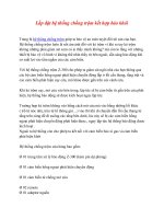
INSPECTION PROCEDURE
(a) Remove the courtesy switch from the hood lock.
(b) Measure the resistance according to the value(s) in the
table below.
Standard resistance
Engine Hood Courtesy Switch Circuit
1
INSPECT ENGINE HOOD COURTESY SWITCH
Certification ECU
A5
Engine Hood Courtesy Switch
HSW
24
E59
2
1
B144359E01
A5
Engine Hood
Courtesy Switch
Free
(ON)
Pushed
(OFF)
B144360E01
Tester Connection Switch Position Specified Condition
1 - 2
Free (ON) Below 1 Ω
Pushed (OFF) 10 kΩ or higher
THEFT DETERRENT – THEFT DETERRENT SYSTEM (w/ Smart Key System)
TD–25
TD
Result
A
B
C
(a) Disconnect the A5 switch connector.
(b) Measure the resistance according to the value(s) in the
table below.
Standard resistance
NG
OK
Result Proceed to
NG (TMC made) A
NG (TMMK made) B
OK C
REPLACE HOOD LOCK ASSEMBLY
REPLACE ENGINE HOOD COURTESY
SWITCH
2
CHECK HARNESS AND CONNECTOR (ENGINE HOOD COURTESY SWITCH - BODY
GROUND)
Wire Harness Side Connector
Front View:
Engine Hood Courtesy Switch
A5
B144361E01
Tester Connection Specified Condition
A5-1 - Body ground Below 1 Ω
REPAIR OR REPLACE HARNESS OR
CONNECTOR