Toyota land cruiser 1998 2007 cooling hệ thống làm mát động cơ trên land cruiser đời 1998 2007
Bạn đang xem bản rút gọn của tài liệu. Xem và tải ngay bản đầy đủ của tài liệu tại đây (464.41 KB, 20 trang )
CO0IO-06
-COOLING COOLANT
CO-1
1762Author: Date:
2004 LAND CRUISER (RM1071U)
COOLANT
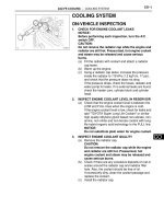
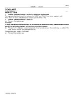
INSPECTION
HINT:
Check the coolant level when the engine is cold.
1. CHECK ENGINE COOLANT LEVEL AT RADIATOR RESERVOIR
The engine coolant level should be between the ”LOW” and ”FULL” lines at normal temperature
(20°C(68°F)).
If low, check for leaks and add ”Toyota Super Long Life Coolant” or similar high quality ethylene glycol based
non-silicate, non-amine, non-nitrite, and non-borate coolant with long-life hybrid organic acid technology
up to the ”FULL” line.
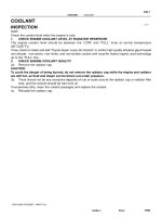
2. CHECK ENGINE COOLANT QUALITY
(a) Remove the radiator cap.
CAUTION:
To avoid the danger of being burned, do not remove the radiator cap while the engine and radiator
are still hot, as fluid and steam can be blown out under pressure.
(b) There should not be any excessive deposits of rust or scale around the radiator cap or radiator filler
hole, and the coolant should be free from oil.
If excessively dirty, clean the coolant passages and replace the coolant.
(c) Reinstall the radiator cap.
CO0IP-10
B04480
Drain Plug
Drain Plug
Drain Plug
CO-2
-COOLING COOLANT
1763Author: Date:
2004 LAND CRUISER (RM1071U)
REPLACEMENT
1. DRAIN ENGINE COOLANT
(a) Remove the radiator cap.
CAUTION:
To avoid the danger of being burned, do not remove the ra-
diator cap while the engine and radiator are still hot, as fluid
and steam can be blown out under pressure.
(b) Remove the 3 drain plugs on the engine and radiator, and
drain the coolant.
(c) Close the 3 drain plugs.
Torque: 12.7 N·m (130 kgf·cm, 9 ft·lbf) for engine
2. REFILL WITH ENGINE COOLANT
(a) Slowly fill the system with coolant.
Capacity:
w/ Front heater: 14.8 liters (15.6 US qts, 13.0 Imp. qts)
w/ Front heater and rear heater:
15.3 liters (16.2 US qts, 13.4 Imp. qts)
NOTICE:
Do not use plain water alone.
HINT:
z Use of improper coolants may damage the engine cooling
system.
z Use ”Toyota Super Long Life Coolant” or similar high qual-
ity ethylene glycol based non-silicate, non-amine, non-
nitrite, and non-borate coolant with long-life hybrid or-
ganic acid technology.
z New Toyota vehicles are filled with Toyota Super Long
Life Coolant (color is pink, premixed ethylene glycol con-
centration is approximately 50 % and freezing tempera-
ture is -35°C (-31°F)). When replacing the coolant, Toyo-
ta Super long Life Coolant is recommended.
z Observe the coolant level inside the radiator by pressing
the inlet and outlet radiator hoses several times by hand.
if the coolant level goes down, add the coolant.
If the coolant level goes down, add the coolant.
(b) Install the radiator cap.
(c) Bleed the cooling system.
(1) Start the engine, and open the heater water valve.
(2) Maintain the engine speed at 2,000 - 2,500 rpm,
and warm up the engine.
(d) Stop the engine, and wait until the engine coolant cools
down.
(e) Refill coolant into the reservoir until it is ”FULL”.
3. CHECK FOR ENGINE COOLANT LEAKS
4. CHECK ENGINE COOLANT SPECIFIC GRAVITY COR-
RECTLY
CO0J0-02
B08313
Radiator Reservoir Tank
Fan Shroud
Radiator Assembly
A/T Oil Cooler Hose
Engine Under Cover No.1
Radiator Assembly
Radiator Upper
Hose
Radiator Lower
Hose
Fan Pulley
Generator Drive Belt
x 8
Fan with
Fluid Coupling
Radiator
Side Support
Insulator
Support Collar
Side Support
12.7 (130, 9)
N·m (kgf·cm, ft·lbf) : Specified torque
5.0 (50, 43in.·lbf )
12.7 (130, 9)
20 (200, 15)
Grommet
A/C Discharge Tube
Wire
Bracket
Clamp
Clamp
Bracket
Clamp
20 (200, 15)
Bracket
20 (200, 15)
CO-16
-COOLING RADIATOR
1777Author: Date:
2004 LAND CRUISER (RM1071U)
COMPONENTS
CO0J2-03
B08321
B04475
B08320
-COOLING RADIATOR
CO-19
1780Author: Date:
2004 LAND CRUISER (RM1071U)
INSTALLATION
1. INSTALL SIDE SUPPORTS TO RADIATOR
(a) Install the 2 side support with 8 nuts.
Torque: 12.7 N·m (130 kgf·cm, 9 ft·lbf)
(b) Install the 2 brackets with the 4 nuts.
Torque: 20 N·m (200 kgf·cm, 13 ft·lbf)
2. INSTALL RADIATOR ASSEMBLY
(a) Place the radiator assembly to the body.
(b) Install the 2 nuts.
Torque: 20 N·m (200 kgf·cm, 15 ft·lbf)
(c) Install the radiator assembly with the 2 bolts to the body.
Torque: 18 N·m (185 kgf·cm, 13 ft·lbf)
3. INSTALL FAN PULLEY, FAN SHROUD, FAN WITH
FLUID COUPLING AND GENERATOR DRIVE BELT
(a) Place the fan with fluid coupling, fan pulley and fan shroud
in position.
(b) Temporarily install the fan pulley mounting nuts.
(c) Install the fan shroud with the 3 bolts.
Torque: 5.0 N·m (50 kgf·cm, 43 in.·lbf)
(d) Connect the A/T oil cooler hoses to the clamp on the fan
shroud.
(e) Install the generator drive belt. (See page CH-16 )
(f) Tighten the 4 fan pulley mounting nuts.
(g) Install the 2 brackets on wire to the radiator wire with 2
bolts.
(h) Install the 2 clamps on the A/C discharge tube to the
brackets on the wire with the 2 nuts.
4. INSTALL RADIATOR RESERVOIR
(a) Install the grommet to the reservoir.
(b) Attach the lower side of the reservoir to the fun shuroud.
(c) install the reservoir with the 2 bolts.
(d) Connect the reservoir hose to the radiator.
(e) Install the clamp on the wire to the radiator.
5. CONNECT A/T OIL COOLER HOSES TO RADIATOR
6. CONNECT RADIATOR UPPER HOSE TO RADIATOR
7. CONNECT RADIATOR LOWER HOSE TO RADIATOR
8. FILL WITH ENGINE COOLANT
9. START ENGINE AND CHECK FOR ENGINE COOLANT
LEAKS
10. RECHECK ENGINE COOLANT LEVEL
CO-20
-COOLING RADIATOR
1781Author: Date:
2004 LAND CRUISER (RM1071U)
11. INSTALL ENGINE UNDER COVER NO.1
B14807
CO1B0-01
CO-14
-COOLING RADIATOR
1775Author: Date:
2004 LAND CRUISER (RM1071U)
RADIATOR
ON-VEHICLE CLEANING
INSPECT FINS FOR BLOCKAGE
If fins are clogged, wash them with water or a steam cleaner and
dry with compressed air.
NOTICE:
z If the distance between the steam cleaner and the
core is too close, there is a possibility of damaging
the fin, so keep the following injection distance.
Injection Pressure Injection Distance
2,942 - 4,903 kpa
(30 - 50 kg/cm
2,
427 -711 psi)
300 mm (11.811 in)
4,903 - 7,845 kpa
(50 - 80 kg/cm
2,
711 - 1,138 psi)
500 mm (19.685 in)
z If the fins are bent, straighten them with a screwdriver
or pliers.
z Never apply water directly onto the electronic compo-
nents.
CO0IZ-01
CO1242
Radiator Cap Tester
Radiator Cap
30° or More
B04467
Radiator Cap Tester
-COOLING RADIATOR
CO-15
1776Author: Date:
2004 LAND CRUISER (RM1071U)
ON-VEHICLE INSPECTION
1. REMOVE RADIATOR CAP
CAUTION:
To avoid the danger of being burned, do not remove the ra-
diator cap while the engine and radiator are still hot, as fluid
and steam can be blown out under pressure.
2. INSPECT RADIATOR CAP
NOTICE:
z If the radiator cap has contaminations, always rinse
it with water.
z Before using a radiator cap tester, wet the relief valve
and pressure valve with engine coolant or water.
z When performing steps (a) and (b) below, keep the
tester at an angle of over 30° above the horizontal.
(a) Using a radiator cap tester, slowly pump the tester and
check that air is coming from the vacuum valve.
Pump speed: 1 push/(3 seconds or more)
NOTICE:
Push the pump at a constant speed.
If air is not coming from the vacuum valve, replace the radiator
cap.
(b) Pump the radiator cap tester, and measure the relief valve
opening pressure.
Pump speed: 1 push within 1 second
NOTICE:
This pump speed is for the first pump only (in order to close
the vacuum valve). After this, the pump speed can be re-
duced.
Standard opening pressure:
93 - 123 kPa (0.95 - 1.25 kgf/cm
2
, 13.5 - 17.8 psi)
Minimum opening pressure:
78 kPa (0.8 kgf/cm
2
, 11.4 psi)
HINT:
Use the tester’s maximum reading as the opening pressure.
If the opening pressure is less than minimum, replace the radia-
tor cap.
3. INSPECT COOLING SYSTEM FOR LEAKS
(a) Fill the radiator with coolant and attach a radiator cap tes-
ter.
(b) Warm up the engine.
(c) Pump it to 118 kPa (1.2 kgf/cm
2
, 17.1 psi), and check that
the pressure does not drop.
If the pressure drops, check the hoses, radiator or water pump
for leaks. If no external leaks are found, check the heater core,
cylinder block and head.
4. REINSTALL RADIATOR CAP
CO0J1-02
B04474
A/T Oil Cooler Hose
B04475
-COOLING RADIATOR
CO-17
1778Author: Date:
2004 LAND CRUISER (RM1071U)
REMOVAL
1. REMOVE ENGINE UNDER COVER NO.1
2. DRAIN ENGINE COOLANT
3. DISCONNECT RADIATOR UPPER HOSE FROM RA-
DIATOR
4. DISCONNECT RADIATOR LOWER HOSE FROM RA-
DIATOR
5. DISCONNECT A/T OIL COOLER HOSES FROM RA-
DIATOR
6. REMOVE RADIATOR RESERVOIR
(a) Disconnect the clamp on the wire from the radiator.
(b) Disconnect the resorvoir hose from the radiator.
(c) Remove the 2 bolts, resorvoir and grommet.
7. REMOVE RADIATOR ASSEMBLY
(a) Remove the 2 nuts, and disconnect the 2 clamps on the
A/C discharge tube from the bracket.
(b) Remove the 2 bolts, and disconnect the 2 brackets on the
wire from the radiator.
(c) Disconnect the A/T oil cooler hoses from the clamp on the
fan shroud.
(d) Loosen the fan pulley mounting nuts holding the fluid cou-
pling to the fan bracket.
(e) Remove generator drive belt. (See page CH-7 )
(f) Remove the 3 bolts holding the fan shroud to the radiator.
(g) Remove the 4 fan pulley mounting nuts.
(h) Pull out the fan with fluid coupling, fan pulley and fan
shroud.
(i) Remove the 2 nuts.
B08320
B08321
CO-18
-COOLING RADIATOR
1779Author: Date:
2004 LAND CRUISER (RM1071U)
(j) Remove the 2 bolts.
(k) Lift out the radiator assembly.
8. REMOVE RADIATOR SIDE SUPPORTS FROM RADIA-
TOR
(a) Remove the 4 nuts and 2 brackets.
(b) Remove the 8 nuts and 2 side supports.
CO0IU-01
B04464
Water Inlet
Thermostat
z Gasket
19 (195, 14)
N·m (kgf·cm, ft·lbf) : Specified torque
z Non-reusable part
CO-10
-COOLING THERMOSTAT
1771Author: Date:
2004 LAND CRUISER (RM1071U)
THERMOSTAT
COMPONENTS
CO0IW-01
P08849
CO0929
CO0949
Valve Lift
CO-12
-COOLING THERMOSTAT
1773Author: Date:
2004 LAND CRUISER (RM1071U)
INSPECTION
INSPECT THERMOSTAT
HINT:
The thermostat is numbered with the valve opening tempera-
ture.
(a) Immerse the thermostat in water and gradually heat the
water.
(b) Check the valve opening temperature.
Valve opening temperature: 80 - 84° C (176 - 183° F)
If the valve opening temperature is not as specified, replace the
thermostat.
(c) Check the valve lift.
Valve lift: 10 mm (0.39 in.) or more at 95° C (203° F)
If the valve lift is not as specified, replace the thermostat.
(d) Check that the valve is fully closed when the thermostat
is at low temperatures (below 40°C (104°F)).
If not closed, replace the thermostat.
CO0IX-02
B04466
Jiggle Valve
30° 30°
-COOLING THERMOSTAT
CO-13
1774Author: Date:
2004 LAND CRUISER (RM1071U)
INSTALLATION
1. PLACE THERMOSTAT IN WATER INLET HOUSING
(a) Install a new gasket to the thermostat.
(b) Insert the thermostat into the water inlet housing with the
jiggle valve facing straight upward.
HINT:
The jiggle valve may be set within 30° of either side of the pre-
scribed position.
2. INSTALL WATER INLET
Install the water inlet with the 3 nuts.
Torque: 19 N·m (195 kgf·cm, 14 ft·lbf)
3. FILL WITH ENGINE COOLANT
4. START ENGINE AND CHECK FOR COOLANT LEAKS
5. RECHECK ENGINE COOLANT LEVEL
CO0IV-01
B04465
-COOLING THERMOSTAT
CO-1 1
1772Author: Date:
2004 LAND CRUISER (RM1071U)
REMOVAL
HINT:
Removal of the thermostat would have an adverse effect, caus-
ing a lowering of cooling efficiency. Do not remove the thermo-
stat, even if the engine tends to overheat.
1. DRAIN ENGINE COOLANT
2. DISCONNECT WATER INLET FROM WATER INLET
HOUSING
Remove the 3 nuts and disconnect the water inlet from the wa-
ter inlet housing.
3. REMOVE THERMOSTAT
(a) Remove the thermostat.
(b) Remove the gasket from the thermostat.
CO0IQ-06
A09750
P/S Air Hose
Radiator
Reservoir Tank
Intake Air
Connector
Radiator Assembly
EVAP Hose
V-Bank Cover
Engine Under Cover No.1
N·m (kgf·cm, ft·lbf) : Specified torque
Generator
Drive Belt
A/C Compressor
A/C Compressor
Connector
A/T Oil Cooler Hose
Fan with
Fluid Coupling
Fan Pulley
49 (500, 36)
5.0 (50, 43 in.·lbf)
18 (185, 13)
Air Hose
x 8
Fan Shroud
Fuel Return
Hose
20 (200, 15)
A/T Oil Cooler
Hose
A/C Discharge
Tube
Clamp
Bracket
Wire
Clamp
Clamp
Lower Radiator Hose
Bracket
-COOLING WATER PUMP
CO-3
1764Author: Date:
2004 LAND CRUISER (RM1071U)
WATER PUMP
COMPONENTS
B04470
RH No.3 Timing Belt Cover
LH No.3 Timing Belt Cover
No.2 Timing Belt Cover
Camshaft Position
Sensor Connector
Engine Wire
Oil Cooler Pipe
Timing Belt
Fan Bracket
Drive Belt Timing Pulley
Timing Belt Tensioner
Dust Boot
N·m (kgf·cm, ft·lbf) : Specified torque
Cover Plate
7.5 (80, 66 in.·lbf)
16 (160, 12)
39 (400,29)
245 (2,500, 181)
32 (330, 24)
16 (160, 12)
7.5 (80, 66 in.·lbf)
Water Bypass
Hose
CO-4
-COOLING WATER PUMP
1765Author: Date:
2004 LAND CRUISER (RM1071U)
B04471
Generator Wire
Generator Connector
Wire Clamp
Generator
Crankshaft Pulley
Drive Belt Tensioner
No.1 Timing Belt Cover
Timing Belt
Timing Belt Guide
(Crankshaft Angle Sensor Plate)
No.2 Idler Pulley
Timing Belt Cover Spacer
Gasket
N·m (kgf·cm, ft·lbf) : Specified torque
z Non-reusable part
Water Inlet Housing
Assembly
Water Pump
z O-Ring
z Gasket
z O-Ring
39 (400, 29)
34.5 (350, 25)
18 (185, 13)
21 (215, 15)
-COOLING WATER PUMP
CO-5
1766Author: Date:
2004 LAND CRUISER (RM1071U)
CO0IS-01
B04067
Air Hole
Water
Hole
-COOLING WATER PUMP
CO-7
1768Author: Date:
2004 LAND CRUISER (RM1071U)
INSPECTION
1. INSPECT WATER PUMP
(a) Visually check the air hole and water hole for coolant leak-
age.
If leakage is found, replace the water pump and timing belt.
(b) Turn the pulley, and check that the water pump bearing
moves smoothly and quietly.
If necessary, replace the water pump.
2. INSPECT TIMING BELT COMPONENTS
(See page EM-20 )
CO0IT-01
B04463
Connect
New O-Ring
B03030
Seal Width
2 - 3 mm
New O-Ring
CO-8
-COOLING WATER PUMP
1769Author: Date:
2004 LAND CRUISER (RM1071U)
INSTALLATION
1. INSTALL WATER PUMP
(a) Install a new O-ring to the water bypass pipe end.
(b) Apply soapy water to the O-ring.
(c) Connect the water pump to the water bypass pipe end.
(d) Install the water pump and new gasket with the 5 bolts, 2
stud bolts and nut. Uniformly tighten the bolts, stud bolts
and nut in several passes.
Torque:
Bolt: 21 N·m (215 kgf·cm, 15 ft·lbf)
Stud bolt and nut: 18 N·m (185 kgf·cm, 13 ft·lbf)
HINT:
Use bolts 35 mm (1.38 in.) in length.
2. INSTALL WATER INLET AND INLET HOUSING AS-
SEMBLY
(a) Remove any old packing (FIPG) material and be careful
not to drop any oil on the contact surfaces of the water in-
let housing and water pump.
z Using a razor blade and gasket scraper, remove all
the old packing (FIPG) material from the gasket sur-
faces and sealing groove.
z Thoroughly clean all components to remove all the
loose material.
z Using a non-residue solvent, clean both sealing
surfaces.
(b) Apply seal packing to the sealing groove of water inlet
housing as shown in the illustration.
Seal packing: Part No. 08826-00100 or equivalent
z Install a nozzle that has been cut to a 2 - 3 mm (0.08
- 0.12 in.) opening.
z Parts must be assembled within 5 minutes of ap-
plication. Otherwise the material must be removed
and reapplied.
z Immediately remove nozzle from the tube and rein-
stall cap.
(c) Install a new O-ring to the water inlet housing.
(d) Apply soapy water on the O-ring.
(e) Attach the water inlet housing end to the front water by-
pass joint hole.
B04460
A
B
-COOLING WATER PUMP
CO-9
1770Author: Date:
2004 LAND CRUISER (RM1071U)
(f) Install the water inlet and housing assembly with the 2
bolts. Alternately tighten the bolts.
Torque: 18 N·m (185 kgf·cm, 13 ft·lbf)
HINT:
Each bolt length is indicated in the illustration.
Bolt length:
76 mm (3.00 in.) for A
22 mm (0.87 in.) for B
3. INSTALL NO.2 IDLER PULLEY (See page EM-22 )
4. INSTALL TIMING BELT (See page EM-22 )
5. FILL WITH ENGINE COOLANT
6. START ENGINE AND CHECK FOR ENGINE COOLANT
LEAKS
7. RECHECK ENGINE COOLANT LEVEL
CO0IR-01
B04460
B04461
CO-6
-COOLING WATER PUMP
1767Author: Date:
2004 LAND CRUISER (RM1071U)
REMOVAL
1. DRAIN ENGINE COOLANT
2. REMOVE TIMING BELT (See page EM-15 )
3. REMOVE NO.2 IDLER PULLEY (See page EM-15 )
4. REMOVE WATER INLET AND INLET HOUSING AS-
SEMBLY
(a) Disconnect the water bypass hose from the water inlet
housing.
(b) Remove the 2 bolts holding the water inlet housing to the
water pump.
(c) Disconnect the water inlet housing from the front water
bypass joint, and remove the water inlet and inlet housing
assembly.
(d) Remove the O-ring from the water inlet housing.
5. REMOVE WATER PUMP
(a) Remove the 5 bolts, 2 stud bolts, nut, water pump and
gasket.
(b) Remove the O-ring from the water bypass pipe.