Toyota land cruiser 1998 2007 emission control hệ thống kiểm soát khí thải trên land cruiser đời 1998 2007
Bạn đang xem bản rút gọn của tài liệu. Xem và tải ngay bản đầy đủ của tài liệu tại đây (328.24 KB, 11 trang )
EC07H-02
-EMISSION CONTROL EMISSION CONTROL SYSTEM
EC-1
1689Author: Date:
2004 LAND CRUISER (RM1071U)
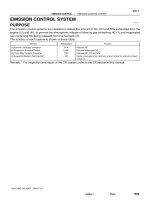
EMISSION CONTROL SYSTEM
PURPOSE
The emission control systems are installed to reduce the amount of HC, CO and NOx exhausted from the
engine ((3) and (4)), to prevent the atmospheric release of blow-by gas-containing HC (1) and evaporated
fuel containing HC being released from the fuel tank (2).
The function of each system is shown in these table:
System Abbreviation Function
(1) Positive Crankcase Ventilation
(2) Evaporative Emission Control
(3) Three-Way Catalytic Converter
(4) Sequential Multiport Fuel Injection*
PCV
EVAP
TWC
SFI
Reduces HC
Reduces evaporated HC
Reduces HC, CO and NOx
Injects a precisely timed, optimum amount of fuel for reduced exhaust
emissions
Remark: * For inspection and repair of the SFI system, refer to the SF section in this manual.
EC0MF-01
B04812
Gasket
B06544
Vacuum
Gauge
I24672
TOYOTA Hand-Held Tester
B06759
Battery
-EMISSION CONTROL EVAPORATIVE EMISSION (EVAP) CONTROL SYSTEM
EC-5
1693Author: Date:
2004 LAND CRUISER (RM1071U)
EVAPORATIVE EMISSION (EVAP)
CONTROL SYSTEM
INSPECTION
1. INSPECT LINES AND CONNECTIONS
Visually check for loose connections, sharp bends or damage.
2. INSPECT FUEL TANK
Visually check for deformation, cracks or fuel leakage.
3. INSPECT FUEL TANK CAP
Visually check if the cap and/or gasket are deformed or dam-
aged.
If necessary, repair or replace the cap.
4. INSPECT EVAP SYSTEM LINE
(a) Warm up the engine and stop the engine.
Allow the engine to warm up to normal operating tempera-
ture.
(b) Install a vacuum gauge (EVAP control system test equip-
ment vacuum gauge) to the EVAP service port on the
purge line.
(c) TOYOTA Hand-Held tester:
Forced driving of the VSV for the EVAP.
(1) Connect a TOYOTA hand-held tester to the DLC3.
(2) Start the engine.
(3) Push the TOYOTA hand-held tester main switch
ON.
(4) Use the ACTIVE TEST mode on the TOYOTA
hand-held tester to operate the VSV for the EVAP.
(d) If you have no TOYOTA Hand-Held Tester:
Forced driving of the VSV for the EVAP.
(1) Disconnect the VSV connector for the EVAP.
(2) Connect the positive (+) and negative (-) leads from
the battery to the VSV terminals for the EVAP.
(3) Start the engine.
B06545
B13332
Hose Clipper
Air Drain Hose
B06546
Pressure
Gauge
Pressure
EC-6
-EMISSION CONTROL EVAPORATIVE EMISSION (EVAP) CONTROL SYSTEM
1694Author: Date:
2004 LAND CRUISER (RM1071U)
(e) Check the vacuum at idle.
Vacuum:
Maintain at 0.368 - 19.713 in.Hg (5 - 268 in.Aq) for over
5 seconds
HINT:
If the vacuum does not change, you can conclude that the hose
connecting the VSV to the service port has come loose or is
blocked, or the VSV is malfunctioning.
(f) TOYOTA Hand-Held Tester:
Conclude forced driving of the VSV for the EVAP.
(1) Stop the engine.
(2) Disconnect the TOYOTA hand-held tester from the
DLC3.
(g) If you have no TOYOTA Hand-Held Tester:
Conclude forced driving of the VSV for the EVAP.
(1) Stop the engine.
(2) Disconnect the positive (+) and negative (-) leads
from the battery from the VSV terminals for the
EVAP.
(3) Connect the VSV connector for the EVAP.
(h) Disconnect the vacuum gauge from the EVAP service
port on the purge line.
(i) Connect a pressure gauge to the EVAP service port on
the purge line.
(j) Check the pressure.
(1) Close off the air drain hose at the marked position
of the canister with a hose clipper or similar instru-
ment.
(2) Add the pressure (13.5 - 15.5 in.Aq) from the EVAP
service port.
Pressure:
2 minutes after the pressure is added, the gauge
should be over 7.7 - 8.8 in.Aq.
HINT:
If you can’t add pressure, you can conclude that the hose con-
necting the VSVXcanisterXfuel tank has slipped off or the
VSV is open.
B06547
Fuel Tank Cap
B13333
EVAP Line Hose
Air
B13334
EVAP Line Hose
Purge Line Hose
Air
-EMISSION CONTROL EVAPORATIVE EMISSION (EVAP) CONTROL SYSTEM
EC-7
1695Author: Date:
2004 LAND CRUISER (RM1071U)
(3) Check if the pressure decreases when the fuel tank
cap is removed while adding pressure.
HINT:
If the pressure does not decrease when the filler cap is re-
moved, then you can conclude that the hose connecting the
service port to the fuel tank is blocked, etc.
(k) Disconnect the pressure gauge from the EVAP service
port on the purge line.
5. CHECK AIRTIGHTNESS IN FUEL TANK AND FILLER
PIPE
(a) Disconnect the EVAP line hose from the charcoal canister
side and then pressurize and make the internal pressure
in the fuel tank 4 kPa (41 gf/cm
2
, 0.58 psi).
(b) Check that the internal pressure of the fuel tank can be
hold for 1 minute.
(c) Check the connected portions of each hose and pipe.
(d) Check the installed parts on the fuel tank.
If there is no abnormality, replace the fuel tank and filler pipe.
(e) Reconnect the EVAP line hose to the charcoal canister.
6. INSPECT FUEL CUTOFF VALVE AND FILL CHECK
VALVE
(a) Disconnect the purge line hose and EVAP line hose from
the charcoal canister.
(b) Plug the cap to the air drain hose.
(c) Pressurize 4 kPa (41 gf/cm
2
, 0.58 psi) to the purge port
and check that there is ventilation through the EVAP line
hose.
HINT:
In the condition that the fuel is full, as the float value of the fill
check valve is closed and has no ventilation, it is necessary to
check the fuel amount (volume).
(d) Check if there is any struck in the vent line hose and EVAP
line hose.
If there is no stuck in hoses, replace the fuel cutoff valve and fill
check valve.
(e) Reconnect the purge line hose and EVAP line hose to the
charcoal canister.
B13335
Air Inlet Hose
Air
B13336
B13337
Air
Purge Port
EVAP Port
Air Drain Port
B13338
Air
Purge Port
EVAP Port
Air Drain Port
Air Inlet Port
B13339
Purge Port
Air Inlet Port
Vacuum
EC-8
-EMISSION CONTROL EVAPORATIVE EMISSION (EVAP) CONTROL SYSTEM
1696Author: Date:
2004 LAND CRUISER (RM1071U)
7. CHECK AIR INLET LINE
(a) Disconnect the air inlet line hose from the charcoal canis-
ter.
(b) Check that there is ventilation in the air inlet line.
(c) Reconnect the air inlet line hose to the charcoal canister.
8. REMOVE CHARCOAL CANISTER ASSEMBLY
9. INSPECT CHARCOAL CANISTER
(a) Visually check the charcoal canister for cracks or dam-
age.
(b) Inspect the charcoal canister operation.
(1) While holding the purge port closed, blow air (1.76
kPa, 18 gf/cm
2
, 0.26 psi) into the EVAP port and
check that air flows from the air drain port.
(2) While holding the purge port and the air drain port
closed, blow air (1.76 kPa, 18 gf/cm
2
, 0.26 psi) into
the EVAP port and check that air does not flow from
the air inlet port.
(3) Apply vacuum (3.43 kPa, 25.7 mmHg, 1.01 in.Hg)
to the purge port, check that the vacuum does not
decrease when the air inlet port is closed, and
check that the vacuum decreases when the air inlet
port is released.
B13340
EVAP Port
Air Inlet Port
Vacuum
Purge Port
-EMISSION CONTROL EVAPORATIVE EMISSION (EVAP) CONTROL SYSTEM
EC-9
1697Author: Date:
2004 LAND CRUISER (RM1071U)
(4) While holding the air inlet port closed, apply vacuum
(3.43 kPa, 25.7 mmHg, 1.01 in Hg) to the EVAP port
and check that air flows into the purge port.
If operation is not as specified, replace the charcoal canister.
(5) Remove the cap from the vent port.
10. INSPECT VSV FOR EVAP (See page SF-44 )
11. INSPECT VSV FOR CANISTER CLOSED VALVE (CCV)
(See page SF-48 )
12. INSPECT VSV FOR VAPOR PRESSURE SENSOR (See
page SF-46 )
13. INSPECT VAPOR PRESSURE SENSOR
(See page SF-52 )
14. REINSTALL CHARCOAL CANISTER ASSEMBLY
EC07K-04
B16803
Cylinder Head Side
Clean Hose
B16804
Intake
Manifold
Side
Clean Hose
B03197
EC-4
-EMISSION CONTROL POSITIVE CRANKCASE VENTILATION (PCV)
SYSTEM
1692Author: Date:
2004 LAND CRUISER (RM1071U)
POSITIVE CRANKCASE
VENTILATION (PCV) SYSTEM
INSPECTION
1. REMOVE V-BANK COVER
2. INSPECT PCV VALVE
(a) Remove the PCV valve.
(b) Install a clean hose to the PCV valve.
(c) Inspect the PCV valve operation.
(1) Blow air into the cylinder head side, and check that
air passes through easily.
CAUTION:
Do not suck air through the valve. Petroleum substances
inside the valve are harmful.
(2) Blow air into the intake manifold side, and check
that air passes through with difficulty.
If operation is not as specified, replace the PCV valve.
(d) Remove the clean hose from the PCV valve.
(e) Reinstall the PCV valve.
3. INSPECT HOSES, CONNECTIONS AND GASKETS
Visually for cracks, leaks or damage.
4. REINSTALL V-BANK COVER
EC07J-08
B16805
Vapor
Pressure
Sensor
Charcoal
Canister
VSV for EVAP
TWC
TWC
EVAP Service Port
Purge Line
EVAP Line
Air Drain Hose
Air Inlet Line
VSV for Pressure
Switching Valve
VSV for Canister Closed Valve
(CCV)
-EMISSION CONTROL PARTS LAYOUT AND SCHEMATIC DRAWING
EC-3
1691A uthor: Date:
2004 LAND CRUISER (RM1071U)
DRAWING
EC07I-09
B16650
VSV for EVAP
Charcoal Canister
Air Intake Line
Purge Line
EVAP Line
Air Drain Hose
TWC
VSV for Pressure
Switching Valve
PCV Valve
EVAP Service port
VSV for Canister
Closed Valve (CCV)
EC-2
-EMISSION CONTROL PARTS LAYOUT AND SCHEMATIC DRAWING
1690A uthor: Date:
2004 LAND CRUISER (RM1071U)
PARTS LAYOUT AND SCHEMATIC DRAWING
LOCATION
EC07M-02
B03194
z
Heated Oxygen Sensor
(Bank 2 Sensor 2)
z Gasket
TWC
z Gasket
z Gasket
20 (200, 14)
z
62 (632, 46)
40 (408, 30)
Heated Oxygen Sensor
(Bank 1 Sensor 2)
z Gasket
z
20 (200, 14)
z Gasket
N·m (kgf·cm, ft·lbf)
z Gasket
z
: Specified torque
z Non-reusable part
z
z
z
z
z
z
z
z
z
LH Front Exhaust Pipe
TWC
40 (408, 30)
62 (632, 46)
z
TWC
RH Front Exhaust Pipe
TWC
EC-10
-EMISSION CONTROL THREE-WAY CATALYTIC CONVERTER (TWC)
SYSTEM
1698Author: Date:
2004 LAND CRUISER (RM1071U)
THREE-W AY CATALYTIC CONVERTER (TWC) SYSTEM
COMPONENTS
EC07N-01
-EMISSION CONTROL THREE-WAY CATALYTIC CONVERTER (TWC)
SYSTEM
EC-1 1
1699Author: Date:
2004 LAND CRUISER (RM1071U)
INSPECTION
1. CHECK EXHAUST PIPE ASSEMBLY
(a) Check the connections for looseness or damage.
(b) Check the clamps for weakness, cracks or damage.
2. INSPECT TWC
Check for dents or damage.
If any part of protector is damaged or dented to the extent that it contacts the TWC, repair or replace it.
3. INSPECT HEAT INSULATOR
(a) Check the heat insulator for damage.
(b) Check for adequate clearance between the TWC and heat insulator.