Toyota land cruiser 1998 2007 lubrication hệ thống bôi trơn trên xe land cruiser đời 1998 2007
Bạn đang xem bản rút gọn của tài liệu. Xem và tải ngay bản đầy đủ của tài liệu tại đây (555 KB, 22 trang )
B16233
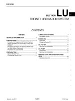
Recommended Viscosity (SAE):
TEMPERATURE RANGE ANTICIPATED BEFORE NEXT OIL CHANGE
5W-30
°C
°F
-20
-29
0
-18
20
-7
40
4
60
16
80
27
100
38
LU08N-04
B04468
Front
B04469
Oil Pressure Gauge
Oil Pressure Switch
P08343
Adhesive
-LUBRICATION OIL AND FILTER
LU-1
1782Author: Date:
2004 LAND CRUISER (RM1071U)
OIL AND FILTER
INSPECTION
1. CHECK ENGINE OIL QUALITY
Check the oil for deterioration, entry of water, discoloring or thin-
ning.
If the quality is visibly poor, replace the oil.
Oil grade:
API grade SL Energy-Conserving or ILSAC multi-
grade engine oil.
2. CHECK ENGINE OIL LEVEL
The oil level should be between the ”L” and ”F” marks on the dip-
stick.
If low, check for leakage and add oil up to the ”F” mark.
NOTICE:
L Do not fill with engine oil above the ”F” mark.
L Install the oil dipstick facing the direction shown in
the illustration.
3. REMOVE ENGINE UNDER COVER NO.1
4. REMOVE OIL PRESSURE SWITCH
5. INSTALL OIL PRESSURE GAUGE
6. WARM UP ENGINE
Allow the engine to warm up to normal operating temperature.
7. CHECK OIL PRESSURE
Oil pressure:
At idle: 29 kPa (0.3 kgf/cm
2
, 4.2 psi) or more
At 3,000 rpm:
294 - 588 kPa (3.0 - 6.0 kgf/cm
2,
43 - 85 psi)
8. REMOVE OIL PRESSURE GAUGE
9. REINSTALL OIL PRESSURE SWITCH
(a) Apply adhesive to 2 or 3 threads of the oil pressure switch.
Adhesive:
Part No. 08833-00080, THREE BOND 1344, LOCTITE
242 or equivalent
(b) Reinstall the oil pressure switch.
10. START ENGINE, AND CHECK FOR ENGINE OIL
LEAKS
11. REINSTALL ENGINE UNDER COVER NO.1
LU08O-02
B04490
Engine Under Cover No.3
B04609
B04481
Service Hole Cover
LU-2
-LUBRICATION OIL AND FILTER
1783Author: Date:
2004 LAND CRUISER (RM1071U)
REPLACEMENT
CAUTION:
L Prolonged and repeated contact with mineral oil will
result in the removal of natural fats from the skin,
leading to dryness, irritation and dermatitis. In addi-
tion, used engine oil contains potentially harmful
contaminants which may cause skin cancer.
L Care should be taken, therefore, when changing en-
gine oil to minimize the frequency and length of time
your skin is exposed to used engine oil. Protective
clothing and gloves that cannot be penetrated by oil
should be worn. The skin should be thoroughly
washed with soap and water, or use water-less hand
cleaner, to remove any used engine oil. Do not use
gasoline, thinners, or solvents.
L In order to preserve the environment, used oil and
used oil filters must be disposed of only at desig-
nated disposal sites.
1. DRAIN ENGINE OIL
(a) Remove the 2 nuts and engine under cover No.3.
(b) Remove the oil filler cap.
(c) Remove the oil drain plug, and drain the oil into a contain-
er.
2. REPLACE OIL FILTER
(a) Remove the 2 bolts and service hole cover.
B04482
SST
B04483
B04484
SST
3/4 Turn
-LUBRICATION OIL AND FILTER
LU-3
1784Author: Date:
2004 LAND CRUISER (RM1071U)
(b) Using SST, remove the oil filter.
SST 09228-07501
(c) Clean the oil filter contact surface on the oil filter mount-
ing.
(d) Lubricate the filter rubber gasket with clean engine oil.
(e) Tighten the oil filter by hand until the rubber gasket con-
tacts the seat of the filter mounting.
(f) Using SST, give it an additional 3/4 turn to seat the filter.
SST 09228-07501
3. REFILL WITH ENGINE OIL
(a) Clean and install the oil drain plug with a new gasket.
Torque: 39 N·m (400 kgf·cm, 29 ft·lbf)
(b) Fill with new engine oil.
Capacity:
Drain and refill:
w/ Oil filter change: 6.8 liters (7.2 US qts, 6.0 Imp. qts)
w/o Oil filter change: 6.4 liters (6.8 US qts, 5.6 Imp. qts)
Dry fill: 8.0 liters (8.5 US qts, 7.0 Imp. qts)
(c) Reinstall the oil filler cap.
4. START ENGINE AND CHECK FOR ENGINE OIL
LEAKS
5. RECHECK ENGINE OIL LEVEL
6. REINSTALL ENGINE UNDER COVER NO.3 AND SER-
VICE HOLE COVER
LU08W-08
B04473
Oil Cooler Hose
L O-Ring
Oil Cooler
Plate Washer
Union Bolt
Oil Filter
N·m (kgf·cm, ft·lbf)
: Specified torque
L Non-reusable part
68.6 (700, 51)
-LUBRICATION OIL COOLER
LU-19
1800Author: Date:
2004 LAND CRUISER (RM1071U)
OIL COOLER
COMPONENTS
LU08Y-06
B04610
-LUBRICATION OIL COOLER
LU-21
1802Author: Date:
2004 LAND CRUISER (RM1071U)
INSPECTION
INSPECT OIL COOLER
Check the oil cooler for damage or clogging.
If necessary, replace the oil cooler.
LU08Z-08
B04611
New O-Ring
B04612
LU-22
-LUBRICATION OIL COOLER
1803Author: Date:
2004 LAND CRUISER (RM1071U)
INSTALLATION
1. INSTALL OIL COOLER
(a) Clean the oil cooler contact surface on the cooler mount-
ing.
(b) Install a new O-ring to the oil cooler.
(c) Apply a light coat of engine oil on the threads and under
the head of the union bolt.
(d) Install the plate washer and union bolt.
Torque: 68.6 N·m (700 kgf·cm, 51 ft·lbf)
(e) Connect the 2 oil cooler hoses to the oil cooler.
2. INSTALL OIL FILTER (See page LU-2 )
3. FILL WITH ENGINE COOLANT
4. START ENGINE AND CHECK FOR ENGINE OIL
LEAKS
5. CHECK ENGINE OIL LEVEL
LU08X-06
B04612
LU-20
-LUBRICATION OIL COOLER
1801Author: Date:
2004 LAND CRUISER (RM1071U)
REMOVAL
1. DRAIN ENGINE COOLANT
2. REMOVE OIL FILTER (See page LU-2 )
3. REMOVE OIL COOLER
(a) Disconnect the 2 oil cooler hoses from the oil cooler.
(b) Remove the union bolt, plate washer and the oil cooler.
(c) Remove the O-ring from the oil cooler.
LU08P-07
B04470
B04791
RH No.3 Timing Belt Cover
LH No.3 Timing Belt Cover
No.2 Timing Belt Cover
Camshaft Position
Sensor Connector
Engine Wire
Drive Belt Idler Pulley
Timing Belt
Fan Bracket
N·m (kgf·cm, ft·lbf) : Specified torque
Oil Cooler Pipe
Timing Belt Tensioner
Dust Boot
Cover Plate
39 (400,29)
245 (2,500, 181)
32 (330, 24)
16 (160, 12)
7.5 (80, 66 in.·lbf)
16 (160, 12)
Water Bypass
Hose
LU-4
-LUBRICATION OIL PUMP
1785Author: Date:
2004 LAND CRUISER (RM1071U)
OIL PUMP
COMPONENTS
B04472
Generator
Drive Belt Tensioner
No.1 Timing Belt Cover
Crankshaft Pulley
Timing Belt
Timing Belt Guide
(Crankshaft Angle Sensor Plate)
No.1 Idler Pulley
Crankshaft Timing Pulley
Plate Washer
No.2 Idler Pulley
Timing Belt Cover Spacer
Gasket
L Precoated part
N·m (kgf·cm, ft·lbf) : Specified torque
39 (400, 29)
34.5 (350, 25)
L
34.5 (350, 25)
-LUBRICATION OIL PUMP
LU-5
1786Author: Date:
2004 LAND CRUISER (RM1071U)
B04485
Oil Pump
Crankshaft Position
Sensor Connector
Crankshaft
Position Sensor
Oil Filter, Oil Cooler and
Filter Bracket Assembly
Oil Cooler Hose
Clamp
Oil Strainer
Oil Dipstick
Guide and
Dipstick
O-Ring
Gasket
No.1 Oil Pan
No.2 Oil Pan
Oil Pan Baffle Plate
Clamp
Gasket
Drain Plug
x 20
N·m (kgf·cm, ft·lbf) : Specified torque
Non-reusable part
Gasket
30.5 (310, 22)
15.5 (160, 11)
O-Ring
15.5 (160, 11)
x 4
x 8
28 (290, 21)
7.5 (80, 66 in.·lbf)
7.5 (80, 66 in.·lbf)
7.5 (80, 66 in.·lbf)
7.5 (80, 66 in.·lbf)
39 (400, 29)
7.5 (80, 66 in.·lbf)
18 (185,13)
15 (153,11)
LU-6
-LUBRICATION OIL PUMP
1787Author: Date:
2004 LAND CRUISER (RM1071U)
B03735
Crankshaft
Front Oil Seal
Compression Spring
Relief Valve
Driven Rotor
Drive Rotor
Oil Pump Body Cover
x 10
Non-reusable part
Snap Ring
Retainer
Oil Pump Body
-LUBRICATION OIL PUMP
LU-7
1788Author: Date:
2004 LAND CRUISER (RM1071U)
LU08R-07
B03740
B03741
-LUBRICATION OIL PUMP
LU-1 1
1792Author: Date:
2004 LAND CRUISER (RM1071U)
DISASSEMBLY
1. REMOVE RELIEF VALVE
(a) Using snap ring pliers, remove the snap ring.
(b) Remove the retainer, spring and relief valve.
2. REMOVE DRIVE AND DRIVEN ROTORS
Remove the 10 screws, pump body cover, the drive and driven
rotors.
LU08S-05
B04454
B04455
Mark
B04456
B04457
B04458
LU-12
-LUBRICATION OIL PUMP
1793Author: Date:
2004 LAND CRUISER (RM1071U)
INSPECTION
1. INSPECT RELIEF VALVE
Coat the valve with engine oil and check that it falls smoothly
into the valve hole by its own weight.
If it doesn’t, replace the relief valve. If necessary, replace the oil
pump assembly.
2. INSPECT DRIVE AND DRIVEN ROTORS INTO OIL
PUMP BODY
Place the drive and driven rotors into the oil pump body with the
mark facing upward.
3. INSPECT ROTORS FOR TIP CLEARANCE
Using a feeler gauge, measure the clearance between the drive
and driven rotor tips.
Standard tip clearance:
0.110 - 0.240 mm (0.0043 - 0.0094 in.)
Maximum tip clearance: 0.35 mm (0.0138 in.)
If the tip clearance is greater than maximum, replace the rotors
as a set.
4. INSPECT ROTORS FOR SIDE CLEARANCE
Using a feeler gauge and precision straight edge, measure the
clearance between the rotors and precision straight edge.
Standard side clearance:
0.030 - 0.090 mm (0.0012 - 0.0035 in.)
Maximum side clearance: 0.15 mm (0.0059 in.)
If the side clearance is greater than maximum, replace the ro-
tors as a set. If necessary, replace the oil pump assembly.
5. INSPECT ROTOR FOR BODY CLEARANCE
Using a feeler gauge, measure the clearance between the driv-
en rotor and body.
Standard body clearance:
0.100 - 0.175 mm (0.0039 - 0.0069 in.)
Maximum body clearance: 0.30 mm (0.0118 in.)
If the body clearance is greater than maximum, replace the ro-
tors as a set. If necessary, replace the oil pump assembly.
6. REMOVE DRIVE AND DRIVE ROTORS
B00960
Seal Width
2 - 3 mm
A
B
A
B
LU08V-03
P21388
New O-Ring
Engage
B00950
A
B
C
D
E
A
A
A
-LUBRICATION OIL PUMP
LU-15
1796Author: Date:
2004 LAND CRUISER (RM1071U)
INSTALLATION
1. INSTALL OIL PUMP
(a) Remove any old packing (FIPG) material and be careful
not to drop any oil on the contact surfaces of the oil pump
and cylinder block.
L Using a razor blade and gasket scraper, remove all
the old packing (FIPG) material from the gasket sur-
faces and sealing groove.
L Thoroughly clean all components to remove all the
loose material.
L Using a non-residue solvent, clean both sealing
surfaces.
(b) Apply seal packing to the oil pump as shown in the illustra-
tion.
Seal packing: Part No. 08826-00080 or equivalent
NOTICE:
Avoid applying an excessive amount to the surface. Be par-
ticularly careful near oil passage.
L Install a nozzle that has been cut to a 2 - 3 mm (0.08
- 0.12 in.) opening.
L Parts must be assembled within 5 minutes of ap-
plication. Otherwise the material must be removed
and reapplied.
L Immediately remove nozzle from the tube and rein-
stall cap.
(c) Install a new O-ring to the cylinder block.
(d) Engage the spline teeth of the oil pump drive gear with the
large teeth of the crankshaft, and slide the oil pump on the
crankshaft.
(e) Install the oil pump with the 8 bolts. Uniformly tighten the
bolts in several passes.
Torque:
15.5 N·m (160 kgf·cm, 11 ft·lbf)
for 12 mm head and 6 mm hexagon head
30.5 N·m (310 kgf·cm, 22 ft·lbf) for 14 mm head
HINT:
L Use a 6 mm hexagon wrench for the hexagon head bolt.
L Each bolt length is indicated in the illustration.
B03739
B04488
A
B
Seal Width
2 - 3 mm
A
B
LU-16
-LUBRICATION OIL PUMP
1797Author: Date:
2004 LAND CRUISER (RM1071U)
Bolt length:
35 mm (1.38 in.) for A of 12 mm head
50 mm (1.97 in.) for B of 12 mm head
106 mm (4.17 in.) for C of 12 mm head
40 mm (1.57 in.) for D of 14 mm head
30 mm (1.18 in.) for E of 6 mm hexagon head
2. INSTALL OIL STRAINER
Install a new gasket and the oil strainer with the 2 bolts and 2
nuts.
Torque: 7.5 N·m (80 kgf·cm, 66 in.·lbf)
HINT:
Use bolt 12 mm (0.47 in.) in length.
3. INSTALL NO.1 OIL PAN
(a) Remove any old packing (FIPG) material and be careful
not to drop any oil on the contact surfaces of the No.1 oil
pan, cylinder block, oil pump and rear oil seal retainer.
L Using a razor blade and gasket scraper, remove all
the old packing (FIPG) material from the gasket sur-
faces and sealing groove.
L Thoroughly clean all components to remove all the
loose material.
L Using a non-residue solvent, clean both sealing
surfaces.
(b) Apply seal packing to the No.1 oil pan as shown in the il-
lustration.
Seal packing: Part No. 08826-00080 or equivalent
L Install a nozzle that has been cut to a 2 - 3 mm (0.08
- 0.12 in.) opening.
L Parts must be assembled within 5 minutes of ap-
plication. Otherwise the material must be removed
and reapplied.
L Immediately remove nozzle from the tube and rein-
stall cap.
B04459
A
B
A
A
A
D
B B B C
B
B
B B
C
C
C
D
B03737
B04489
A
B
Seal Width
2 - 3 mm
A
B
-LUBRICATION OIL PUMP
LU-17
1798Author: Date:
2004 LAND CRUISER (RM1071U)
(c) Temporarily install the No.1 oil pan with the 19 bolts, stud
bolt and 2 nuts.
HINT:
Each bolt length is indicated in the illustration.
Bolt length:
20 mm (0.79 in.) for A of 10 mm head
25 mm (0.98 in.) for B of 12 mm head
60 mm (2.36 in.) for C of 12 mm head
35 mm (1.38 in.) for D of 10 mm head
(d) Set the No.1 oil pan as shown in the illustration.
NOTICE:
Make sure the clearance between the rear ends of the No.1
oil pan and cylinder block is 0.2 mm (0.008 in.) or less. If the
clearance is more than 0.2 mm (0.008 in.), the No.1 oil pan
will be stretched.
(e) Uniformly tighten the bolts, and nuts in several passes.
Torque:
7.5 N·m (80 kgf·cm, 66 in.·lbf) for 10 mm head
28 N·m (290 kgf·cm, 21 ft·lbf) for 12 mm head
4. INSTALL OIL PAN BAFFLE PLATE
Install the baffle plate with the 4 bolts and 2 nuts.
Torque: 7.5 N·m (80 kgf·cm, 66 in.·lbf)
HINT:
Use bolts 12 mm (0.55 in.) in length.
5. INSTALL NO.2 OIL PAN
(a) Remove any old packing (FIPG) material and be careful
not to drop any oil on the contact surfaces of the No.1 and
No.2 oil pans.
L Using a razor blade and gasket scraper, remove all
the old packing (FIPG) material from the gasket sur-
faces and sealing groove.
L Thoroughly clean all components to remove all the
loose material.
L Using a non-residue solvent, clean both sealing
surfaces.
NOTICE:
Do not use a solvent which will affect the painted surfaces.
(b) Apply seal packing to the No.2 oil pan as shown in the il-
lustration.
Seal packing: Part No. 08826-00080 or equivalent
L Install a nozzle that has been cut to a 3 - 4 mm (0.12
- 0.16 in.) opening.
B04486
Push
New O-Ring
LU-18
-LUBRICATION OIL PUMP
1799Author: Date:
2004 LAND CRUISER (RM1071U)
L Parts must be assembled within 5 minutes of ap-
plication. Otherwise the material must be removed
and reapplied.
L Immediately remove nozzle from the tube and rein-
stall cap.
(c) Install the No.2 oil pan with the 20 bolts and 2 nuts. Uni-
formly tighten the bolts and nuts in several passes.
Torque: 7.5 N·m (80 kgf·cm, 66 in.·lbf)
HINT:
Use bolts 14 mm (0.55 in.) in length.
6. INSTALL CRANKSHAFT POSITION SENSOR
(See page IG-13 )
7. INSTALL OIL FILTER, OIL COOLER AND FILTER
BRACKET ASSEMBLY
(a) Install the a new gasket to the oil filter bracket.
(b) Install the oil filter, oil cooler and filter bracket assembly
with the 2 bolts and nut.
Torque: 18 N·m (185 kgf·cm, 13 ft·lbf)
(c) Connect the oil pressure switch connector.
8. INSTALL OIL DIPSTICK GUIDE AND DIPSTICK
(a) Install a new O-ring to the dipstick guide.
(b) Apply soapy water to the O-ring.
(c) Push in the dipstick guide end into the guide hole of the
No.1 oil pan.
(d) Install the dipstick guide with the bolt.
Torque: 15 N·m, (155 kgf·cm, 11 ft·lbf)
(e) Install the dipstick.
9. INSTALL CRANKSHAFT TIMING PULLEY
(See page EM-22 )
10. INSTALL NO.1 IDLER PULLEY (See page EM-22 )
11. INSTALL NO.2 IDLER PULLEY (See page EM-22 )
12. INSTALL TIMING BELT (See page EM-22 )
13. DISCONNECT ENGINE FROM ENGINE STAND
14. INSTALL ENGINE TO VEHICLE (See page EM-81 )
LU08U-05
B04455
Mark
B03741
B03740
LU-14
-LUBRICATION OIL PUMP
1795Author: Date:
2004 LAND CRUISER (RM1071U)
REASSEMBLY
1. INSTALL DRIVE AND DRIVEN ROTORS
(a) Place the drive and driven rotors into pump body with the
marks facing the pump body cover side.
(b) Install the pump body cover with the 10 screws.
Torque: 10 N·m (105 kgf·cm, 7 ft·lbf)
2. INSTALL RELIEF VALVE
(a) Insert the relief valve, spring and retainer into the oil pump
body hole.
(b) Using snap ring pliers, install the snap ring.
LU08Q-08
B04486
Pull
O-Ring
B03736
B04629
SST
SST
LU-8
-LUBRICATION OIL PUMP
1789Author: Date:
2004 LAND CRUISER (RM1071U)
REMOVAL
HINT:
When repairing the oil pump, the oil pan and strainer should be
removed and cleaned.
1. REMOVE ENGINE FROM VEHICLE
(See page EM-77 )
2. INSTALL ENGINE TO ENGINE STAND FOR DIS-
ASSEMBLY
3. REMOVE TIMING BELT (See page EM-15 )
4. REMOVE NO.1 IDLER PULLEY (See page EM-15 )
5. REMOVE NO.2 IDLER PULLEY (See page EM-15 )
6. REMOVE CRANKSHAFT TIMING PULLEY
(See page EM-15 )
7. REMOVE OIL DIPSTICK AND GUIDE
(a) Remove the bolt holding the oil dipstick to the LH cylinder
head.
(b) Pull out the dipstick guide together with the dipstick from
the No.1 oil pan.
(c) Remove the O-ring from the dipstick guide.
8. REMOVE OIL FILTER, OIL COOLER AND FILTER
BRACKET ASSEMBLY
(a) Disconnect the oil pressure switch connector.
(b) Remove the 2 bolts, nut, and oil filter, oil cooler and filter
bracket assembly.
(c) Remove the gasket from the filter bracket.
9. REMOVE CRANKSHAFT POSITION SENSOR
(See page IG-12 )
10. REMOVE NO.2 OIL PAN
(a) Remove the 20 bolts and 2 nuts.
(b) Insert the blade of SST between the No.1 and No.2 oil
pans, cut off applied sealer and remove the No.2 oil pan.
SST 09032-00100
NOTICE:
L Be careful not to damage the No.2 oil pan contact sur-
face of the No.1 oil pan.
L Be careful not to damage the No.2 oil pan flange.
B03737
B03738
B05144
Ply
B03739
-LUBRICATION OIL PUMP
LU-9
1790Author: Date:
2004 LAND CRUISER (RM1071U)
11. REMOVE OIL PAN BAFFLE PLATE
Remove the 4 bolts, 2 nuts and baffle plate.
12. REMOVE NO.1 OIL PAN
(a) Remove the 18 bolts and 2 nuts.
(b) Using a screwdriver, remove the No.1 oil pan by prying
between the oil pan and cylinder block in the sequence
shown.
NOTICE:
Be careful not to damage the contact surface of the cylin-
der block and No.1 oil pan.
13. REMOVE OIL STRAINER
Remove the 2 bolt, 2 nuts, oil strainer and gasket.
B01044
B00951
LU-10
-LUBRICATION OIL PUMP
1791Author: Date:
2004 LAND CRUISER (RM1071U)
14. REMOVE OIL PUMP
(a) Remove the 8 bolts.
HINT:
Use a 6 mm hexagon wrench for the hexagon head bolt.
(b) Using a screwdriver, remove the oil pump by prying the
portions between the oil pump and cylinder block.
NOTICE:
Be careful not to damage the contact surface of the cylin-
der block and oil pump.
(c) Remove the O-ring from the cylinder block.
LU08T-02
-LUBRICATION OIL PUMP
LU-13
1794Author: Date:
2004 LAND CRUISER (RM1071U)
REPLACEMENT
REPLACE CRANKSHAFT FRONT OIL SEAL (See page EM-104 )