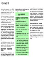
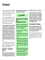
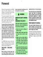
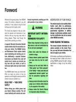
toyota rav4 1994-2000 manual transaxle - hộp số sàn trên xe toyota rav4 đời 1994-2000
Bạn đang xem bản rút gọn của tài liệu. Xem và tải ngay bản đầy đủ của tài liệu tại đây (2.3 MB, 97 trang )
MX01Z−08
−MANUAL TRANSAXLE TROUBLESHOOTING
MX−1
1996 RAV4 (RM447U)
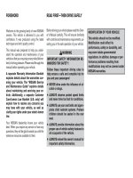
TROUBLESHOOTING
PROBLEM SYMPTOMS TABLE
Use the table below to help you find the cause of the problem. The numbers indicate the priority of the likely
cause of the problem. Check each part in order. If necessary, replace these parts.
Symptom Suspect Area See page
Noise
14.Oil (Level low) 2WD
4WD
15. Oil (Wrong) 2WD
4WD
16.Gear (Worn or damaged)
17.Bearing (Worn or damaged)
MX−3
MX−9
MX−3
MX−9
MX−12
MX−79
MX−12
MX−79
Oil leakage
1. Oil (Level too high) 2WD
4WD
2. Gasket (Damaged)
3. Oil seal (Worn or damaged)
4. O−Ring (Worn or damaged)
MX−3
MX−9
MX−12
MX−79
MX−12
MX−79
MX−12
MX−78
MX−79
Hard to shift or will not shift
1. Control cable (Faulty)
2. Synchronizer ring (Worn or damaged)
3. Shift key spring (Damaged)
MX−77
MX−12
MX−29
MX−36
MX−12
MX−29
MX−36
Jumps out of gear
1. Locking ball spring (Damaged)
2. Shift fork (Worn)
3. Gear (Worn or damaged)
4. Bearing (Worn or damaged)
MX−12
MX−12
MX−79
MX−12
MX−79
MX−12
MX−79
Tight corner braking
1. Differential, Center differential (Faulty) MX−58
MX−72
MX05N−02
Q10400
Air Intake Connector
Engine Coolant
Reservoir Tank
Clutch Release Cylinder
and Line
Vehicle Speed
Sensor Connector
Back−Up Light Switch
Connector
Control Cable
Clip
Ground Cable
Transaxle Case Protector
Tie Rod End
RH Drive Shaft
Stiffener Plate
No.2 Rear
End Plate
z Snap Ring
z Cotter Pin
LH Drive
Shaft
PS Gear Assembly
Engine Mounting
Center Member
RH Engine
Under Cover
LH Engine Under Cover
Front Suspension Crossmember
Assembly with Stabilizer Bar
Clip
Air Cleaner Case
Assembly
with Air Hose
Snap Ring
Engine
Wire
Clamp
z Cotter Pin
Lock Cap
Starter
N·m (kgf·cm, ft·lbf)
: Specified torque
z Non−reusable part
z
z
z
4.9 (50, 43 in.·lbf)
12 (120, 9)
29 (300, 22)
35 (360, 26)
32 (330, 24)
46 (470, 34)
64 (650, 47)
35 (360, 26)
64 (650, 47)
12 (120, 9)
64 (650, 47)
25 (250, 18)
25 (250, 18)
9.0 (95, 78 in.·lbf)
37 (380, 27)
39 (400, 29)
9.0 (95, 78 in.·lbf)
29 (300, 22)
37 (380, 27)
49 (500, 36)
113 (1,150, 83)
137 (1,400, 101)
206 (2,100, 152)
216 (2,200, 159)
113 (1,150, 83)
64 (650, 47)
48 (490, 35)
80 (820, 59)
115 (1,170, 85)
127 (1,300, 94)
z
62 (630, 46)
Front Exhaust Pipe
z Gasket
Clip
Washer
MX−2
−MANUAL TRANSAXLE MANUAL TRANSAXLE UNIT (2WD)
1996 RAV4 (RM447U)
MANUAL TRANSAXLE UNIT (2WD)
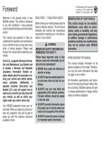
COMPONENTS
MX05O−02
Q08747
Q08748
A
B
Q08749
Q08750
A
B
A
−MANUAL TRANSAXLE MANUAL TRANSAXLE UNIT (2WD)
MX−3
1996 RAV4 (RM447U)
REMOVAL
1. REMOVE AIR CLEANER CASE ASSEMBLY WITH AIR
HOSE
2. REMOVE ENGINE COOLANT RESERVOIR TANK
3. REMOVE ENGINE WIRE CLAMP SET NUT
4. REMOVE STARTER
(a) Disconnect the connector and wire from the starter.
(b) Remove the 2 bolts and starter.
Torque: 39 N·m (400 kgf·cm, 29 ft·lbf)
5. DISCONNECT CLUTCH RELEASE CYLINDER AND
LINE
(a) Remove the 2 set bolts of the clutch line bracket.
Torque:
Bolt A: 12 N·m (120 kgf·cm, 9 ft·lbf)
Bolt B: 4.9 N·m (50 kgf·cm, 43 in.·lbf)
(b) Remove the 2 bolts, release cylinder and line.
Torque: 12 N·m (120 kgf·cm, 9 ft·lbf)
6. DISCONNECT GROUND CABLE
Remove the set bolt of the ground cable from the transaxle.
7. DISCONNECT VEHICLE SPEED SENSOR AND
BACK−UP LIGHT SWITCH CONNECTORS
8. DISCONNECT CONTROL CABLE
(a) Remove the 2 clips and washers.
(b) Remove the 2 clips from the cables.
9. REMOVE 4 TRANSAXLE UPPER SIDE MOUNTING
BOLTS
Torque:
Bolt A: 64 N·m (650 kgf·cm, 47 ft·lbf)
Bolt B: 35 N·m (360 kgf·cm, 26 ft·lbf)
Q08751
Q08752
Q10165
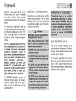
Filler Plug
Oil Level
0 − 5 mm
Drain Plug
Q08753
MX−4
−MANUAL TRANSAXLE MANUAL TRANSAXLE UNIT (2WD)
1996 RAV4 (RM447U)
10. REMOVE ENGINE LEFT MOUNTING INSULATOR SET
BOLT AND 2 NUTS
Torque: 64 N·m (650 kgf·cm, 47 ft·lbf)
11. INSTALL ENGINE SUPPORT FIXTURE
12. TIE PS GEAR ASSEMBLY TO ENGINE SUPPORT FIX-
TURE BY CORD OR EQUIVALENT
13. REMOVE FRONT WHEEL
Torque: 103 N·m (1,050 kgf·cm, 76 ft·lbf)
14. RAISE VEHICLE
NOTICE:
Make sure that the vehicle is securely supported.
15. REMOVE LH AND RH ENGINE UNDER COVERS
16. DRAIN TRANSAXLE OIL
Oil grade: API GL−4 or GL−5
Viscosity: SAE 75W−90
Capacity: 3.9 liters (4.1 US qts, 3.4 Imp. qts)
Torque: 49 N·m (500 kgf·cm, 36 ft·lbf)
17. REMOVE LH AND RH FRONT DRIVE SHAFTS
(See page SA−18)
18. REMOVE FRONT EXHAUST PIPE
(a) Remove the 3 nuts and gasket from the exhaust manifold.
Torque: 62 N·m (630 kgf·cm, 46 ft·lbf)
(b) Remove the 2 bolts, gasket and pipe.
Torque: 48 N·m (490 kgf·cm, 35 ft·lbf)
19. REMOVE FRONT SUSPENSION CROSSMEMBER AS-
SEMBLY WITH STABILIZER BAR
(a) Support the front suspension crossmember with a jack.
(b) Disconnect the ring from the center exhaust pipe.
(c) Remove the 2 set bolts and nuts of the PS gear assembly.
Torque: 113 N·m (1,150 kgf·cm, 83 ft·lbf)
Q08754
A
B
A
B
D
E
C
Q08755
Q08756D
E
C
C
F
G
G
F
−MANUAL TRANSAXLE MANUAL TRANSAXLE UNIT (2WD)
MX−5
1996 RAV4 (RM447U)
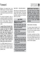
(d) Remove the 2 nuts, 6 bolts and front suspension cross-
member assembly with the stabilizer bar.
Torque:
Bolt A: 206 N·m (2,100 kgf·cm, 152 ft·lbf)
Bolt B: 137 N·m (1,400 kgf·cm, 101 ft·lbf)
Nut C: 115 N·m (1,170 kgf·cm, 85 ft·lbf)
20. REMOVE ENGINE MOUNTING CENTER MEMBER
Remove the 4 bolts and center member.
Torque:
Bolt D: 80 N·m (820 kgf·cm, 59 ft·lbf)
Bolt E: 35 N·m (360 kgf·cm, 26 ft·lbf)
21. JACK UP TRANSAXLE SLIGHTLY
Using a trasmission jack, support the transaxle.
22. DISCONNECT ENGINE LEFT MOUNTING BRACKET
FROM ENGINE LEFT MOUNTING INSULATOR
Remove the set bolt of the engine left mounting bracket.
Torque: 64 N·m (650 kgf·cm, 47 ft·lbf)
23. REMOVE STIFFENER PLATE, NO.2 REAR END
PLATE AND TRANSAXLE LOWER SIDE MOUNTING
BOLT
(a) Remove the 2 bolts and stiffener plate.
Torque:
Bolt G: 37 N·m (380 kgf·cm, 27 ft·lbf)
(b) Remove the 7 bolts and No.2 rear end plate.
Torque:
Bolt C: 29 N·m (300 kgf·cm, 22 ft·lbf)
Bolt D: 46 N·m (470 kgf·cm, 34 ft·lbf)
Bolt E: 25 N·m (250 kgf·cm, 18 ft·lbf)
Bolt F: 9.0 N·m (95 kgf·cm, 78 in.·lbf)
24. REMOVE TRANSAXLE
Lower the engine left side and remove the transaxle from the
engine.
HINT:
At the time of installation, please refer to the following items.
S Align the input shaft with the clutch disc and install the
transaxle to the engine.
S Temporarily tighten the transaxle mounting bolts.
MX−6
−MANUAL TRANSAXLE MANUAL TRANSAXLE UNIT (2WD)
1996 RAV4 (RM447U)
25. REMOVE TRANSAXLE CASE PROTECTOR
Remove the 2 bolts and protector.
Torque: 25 N·m (250 kgf·cm, 18 ft·lbf)
MX05P−05
−MANUAL TRANSAXLE MANUAL TRANSAXLE UNIT (2WD)
MX−7
1996 RAV4 (RM447U)
INSTALLATION
Installation is in the reverse order of removal.
(See page MX−3)
NOTICE:
When working with FIPG material, you must observe the following items.
S Using a razor blade and gasket scraper, remove all the old FIPG material from the gasket surfaces.
S Thoroughly clean all components to remove all the loose material.
S Clean both sealing surfaces with a non−residue solvent.
S Apply FIPG in an approx. 1 mm (0.04 in.) wide bead along the sealing surface.
S Parts must be assembled within 10 minutes of application. Otherwise, the FIPG material must be re-
moved and reapplied.
HINT:
After installation, check and inspect items as follows.
S Front wheel alignment (See page SA−4).
S Do the road test.
MX05R−02
Q09030
Solenoid Hose No.1
Transfer Vacuum Actuator
Bracket
Transfer Vacuum Actuator Assembly
Right Transfer Stiffener Plate
Center Transfer Stiffener Plate
Differential Lock Indicator Switch Connector
Back−Up Light
Switch Connector
Vehicle Speed
Sensor Connector
Transaxle Case Protector
Starter
Stiffener Plate
N·m (kgf·cm, ft·lbf)
: Specified torque
25 (250, 18)
37 (380, 27)
9.0 (95, 78 in.·lbf)
37 (380, 27)
37 (380, 27)
37 (380, 27)
37 (380, 27)
37 (380, 27)
37 (380, 27)
37 (380, 27)
37 (380, 27)
37 (380, 27)
46 (470, 34)
29 (300, 22)
25 (250, 18)
64 (650, 47)
39 (400, 29)
64 (650, 47)
35 (360, 26)
29 (300, 22)
Solenoid Hose No.0
Solenoid Hose No.2
Solenoid Hose No.0
MX−8
−MANUAL TRANSAXLE MANUAL TRANSAXLE UNIT (4WD)
1996 RAV4 (RM447U)
MANUAL TRANSAXLE UNIT (4WD)
COMPONENTS
MX05S−01
Q09031
B
A
C
F
E
D
A
A
C
Q08759
No.1
No.2
No.0
No.0
−MANUAL TRANSAXLE MANUAL TRANSAXLE UNIT (4WD)
MX−9
1996 RAV4 (RM447U)
REMOVAL
1. REMOVE TRANSAXLE WITH ENGINE
(See page EM−80)
2. REMOVE TRANSAXLE CASE PROTECTOR
Remove the 2 bolts and transaxle case protector.
Torque: 25 N·m (250 kgf·cm, 18 ft·lbf)
3. REMOVE STARTER
(a) Disconnect the connector and wire from the starter.
(b) Remove the 2 bolts and starter.
Torque: 39 N·m (400 kgf·cm, 29 ft·lbf)
4. DISCONNECT DIFFERENTIAL LOCK INDICATOR
SWITCH, BACK−UP LIGHT SWITCH AND VEHICLE
SPEED SENSOR CONNECTORS
5. REMOVE TRANSFER VACUUM ACTUATOR BRACK-
ET
Remove the 4 bolts and bracket.
Torque: 37 N·m (380 kgf·cm, 27 ft·lbf)
6. REMOVE TRANSFER VACUUM ACTUATOR AS-
SEMBLY
(a) Disconnect the 4 solenoid hoses from the transfer vacu-
um actuator assembly.
NOTICE:
At the time of installation, please refer to the following item.
Check that the hose No.0, No.1 and No.2 are securely
installed to the solenoid.
(b) Remove the 2 bolts and transfer vacuum actuator assem-
bly.
Torque: 37 N·m (380 kgf·cm, 27 ft·lbf)
7. REMOVE RIGHT TRANSFER STIFFENER PLATE
Remove the 5 bolts and right transfer stiffener plate.
Torque: 37 N·m (380 kgf·cm, 27 ft·lbf)
8. REMOVE CENTER TRANSFER STIFFENER PLATE
Remove the 3 bolts and center transfer stiffener plate.
Torque: 37 N·m (380 kgf·cm, 27 ft·lbf)
9. REMOVE STIFFENER PLATE
Remove the 2 bolts and stiffener plate.
Torque: 37 N·m (380 kgf·cm, 27 ft·lbf)
10. REMOVE TRANSAXLE FROM ENGINE
(a) Remove the 9 transaxle mounting bolts from the engine.
Torque:
Bolt A: 64 N·m (650 kgf·cm, 47 ft·lbf)
Bolt B: 35 N·m (360 kgf·cm, 26 ft·lbf)
Bolt C: 29 N·m (300 kgf·cm, 22 ft·lbf)
Bolt D: 46 N·m (470 kgf·cm, 34 ft·lbf)
Bolt E: 25 N·m (250 kgf·cm, 18 ft·lbf)
Bolt F: 9.0 N·m (95 kgf·cm, 78 in.·lbf)
Q06187
Q06188
Q06189
MX−10
−MANUAL TRANSAXLE MANUAL TRANSAXLE UNIT (4WD)
1996 RAV4 (RM447U)
(b) Pull straight until there is a gap of about 60−80 mm
(2.4−3.1 in.) between the engine and transaxle case.
(c) Move the transmission case cover in the direction, as
shown in the illustration.
(d) While holding transfer output, gently pull out whole trans-
axle.
MX05T−03
−MANUAL TRANSAXLE MANUAL TRANSAXLE UNIT (4WD)
MX−11
1996 RAV4 (RM447U)
INSTALLATION
Installation is in the reverse order of removal.
(See page MX−9)
NOTICE:
When working with FIPG material, you must observe the following items.
S Using a razor blade and gasket scraper, remove all the old FIPG material from the gasket surfaces.
S Thoroughly clean all components to remove all the loose material.
S Clean both sealing surfaces with a non−residue solvent.
S Apply FIPG in an approx. 1 mm (0.04 in.) wide bead along the sealing surface.
S Parts must be assembled within 10 minutes of application. Otherwise, the FIPG material must be re-
moved and reapplied.
HINT:
After installation, do the road test.
MX05U−01
Q09032
2WD:
Clutch Release Fork Assembly
with Bearing
Clutch Release Fork Support
Control Lever Housing
Support Bracket
Boot
z O−Ring
Cover
Clutch Release
Line Bracket
Transaxle Case
Transmission
Oil Cooler
Sub−Assembly
Elbow
z O−Ring
Vehicle Speed Sensor
Transaxle Case Receiver
Transmission Oil
Pipe
Magnet
Transmission
Oil Pipe
z Output Shaft Cover
Tapered Roller Bearing
Outer Race
z Front Oil Seal
Input Shaft Front
Bearing
Transmission Oil Pump
Assembly
Differential Case Assembly
Oil Pump Drive Gear
17 (175, 13)
47 (480, 35)
34 (350, 25)
27 (275, 20)
7.4 (75, 65 in.·lbf)
17 (175, 13)
17 (175, 13)
17 (175, 13)
17 (175, 13)
17 (175, 13)
17 (175, 13)
N·m (kgf·cm, ft·lbf)
: Specified torque
z Non−reusable part
z Gasket
z
z
MX−12
−MANUAL TRANSAXLE MANUAL TRANSAXLE ASSEMBLY
1996 RAV4 (RM447U)
MANUAL TRANSAXLE ASSEMBLY
COMPONENTS
Q09033
Clutch Release
Fork Assembly
with Bearing
Clutch Release Fork Support
Control Lever Housing
Support Bracket
Boot
z O−Ring
Cover
Clutch Release
Line Bracket
Transaxle Case
Elbow
z O−Ring
Vehicle Speed Sensor
Transaxle Case Receiver
Transmission Oil
Pipe
Magnet
z Output Shaft Cover
z Tapered Roller Bearing
Outer Race
z Front Oil Seal
z Input Shaft Front
Oil Seal
Transmission Oil Pump
Assembly
Differential Case Assembly
Oil Pump Drive Gear
34 (350, 25)
27 (275, 20)
7.4 (75, 65 in.·lbf)
17 (175, 13)
17 (175, 13)
17 (175, 13)
17 (175, 13)
17 (175, 13)
17 (175, 13)
N·m (kgf·cm, ft·lbf)
: Specified torque
z Non−reusable part
L Precoated part
4WD:
L
L
Transfer Assembly
Transmission
Oil Pipe
17 (175, 13)
17 (175, 13)
69 (700, 51)
69 (700, 51)
39 (400, 29)
47 (480, 35)
Differential Side Gear
Intermediate Shaft
z Snap Ring
69 (700, 51)
Drain Plug
Oil Cooler Line
z Gasket
z Gasket
L
−MANUAL TRANSAXLE MANUAL TRANSAXLE ASSEMBLY
MX−13
1996 RAV4 (RM447U)
Q09034
L
N·m (kgf·cm, ft·lbf)
: Specified torque
z Non−reusable part
L Precoated part
Transmission Case Cover
Transmission Case
No.2 Selecting Bellcrank with
Selecting Bellcrank Support
Shift and Select Lever
Shaft Assembly
No.1 Oil Receiver Pipe
Reverse Restrict
Pin
L Straight Screw Plug
Back−Up Light Switch
No.3 Shift Fork
No.3 Shift Fork Shaft
Interlock Roller
Snap Ring
Shift Head
Shift and Select Lever
Shaft Lock Bolt
No.2 Shift Fork Shaft
L Straight Screw Plug
Reverse Shift Arm Bracket Assembly
Snap Ring
Reverse Shift Fork
No.1 Shift Fork
No.1 Shift Fork Shaft
Seat
Spring
Ball
Slotted Spring
Pin
Snap Ring
Snap Ring
No.2 Shift Fork
No.2 Oil Receiver Pipe
Drain Plug
Filler Plug
x10
x17
L
L
L
L
24 (240, 17)
25 (250, 18)
25 (250, 18)
24 (240, 17)
24 (240, 17)
L
25 (250, 18)
17 (175, 13)
40 (410, 30)
13 (130, 9)
49 (500, 36)
20 (200, 14)
17 (175, 13)
29 (300, 22)
49 (500, 36)
20 (200, 14)
49 (500, 36)
49 (500, 36)
29 (300, 22)
Breather Plug
z Gasket
z Gasket
L
z Gasket
z Gasket
z Gasket
z Gasket
MX−14
−MANUAL TRANSAXLE MANUAL TRANSAXLE ASSEMBLY
1996 RAV4 (RM447U)
Z17555
N·m (kgf·cm, ft·lbf)
: Specified torque
z Non−reusable part
L Precoated part
Output Shaft Assembly
Input Shaft Assembly
z Tapered Roller Bearing
Outer Race
Reverse Idler Gear Shaft
Reverse Idler Gear
Thrust Washer
Rear Bearing Retainer
Needle Roller Bearing
5th Driven Gear
Synchronizer Pull Ring
Key Spring
Middle Synchronizer
Ring
Snap Ring
z Output Shaft
Lock Nut
5th Gear
No.3 Clutch Hub
No.3 Hub Sleeve
Key Spring
Outer Synchronizer Ring
Inner Synchronizer Ring
Snap Ring
Spacer
x7
Shim
L Lock Bolt
29 (300, 22)
42 (430, 31)
123 (1,250, 90)
Snap Ring
L
−MANUAL TRANSAXLE MANUAL TRANSAXLE ASSEMBLY
MX−15
1996 RAV4 (RM447U)
MX05V−02
Q08757
FIPG
Z12375
SST
Q09043
255.5 mm
MX−16
−MANUAL TRANSAXLE MANUAL TRANSAXLE ASSEMBLY
1996 RAV4 (RM447U)
DISASSEMBLY
1. 4WD:
REMOVE TRANSFER ASSEMBLY
(a) Remove the 3 bolts.
Sealant:
Part No. 08833−00080, THREE BOND 1344, LOCTITE
242 or equivalent
Torque: 69 N·m (700 kgf·cm, 51 ft·lbf)
(b) Remove the 5 nuts.
Torque: 69 N·m (700 kgf·cm, 51 ft·lbf)
(c) Using a plastic hammer, remove the transfer assembly
from the transaxle.
HINT:
At the time of reassembly, please refer to the following item.
Shift into the 4th gear, and install the transfer assembly while
turning the input shaft of the transaxle.
FIPG:
Part No. 08826−00090, THREE BOND 1281 or equiva-
lent
2. 4WD:
REMOVE DIFFERENTIAL SIDE GEAR INTERMEDI-
ATE SHAFT
(a) Screw in a suitable bolt with a washer into the side gear
intermediate shaft.
(b) Using SST, remove the side gear intermediate shaft.
SST 09910−00015 (09911−00011, 09912−00010)
(c) Remove the snap ring from the differential side gear inter-
mediate shaft.
HINT:
At the time of reassembly, please refer to the following item.
Keeping the intermediate shaft on the differential pinion shaft,
measure the dimension, as shown in the illustration.
Protrusion length: 255.5 mm (10.06 in.)
3. REMOVE RELEASE FORK AND BEARING
4. REMOVE BACK−UP LIGHT SWITCH WITH GASKET
Torque: 40 N·m (410 kgf·cm, 30 ft·lbf)
5. REMOVE BOLT AND VEHICLE SPEED SENSOR
Torque: 17 N·m (175 kgf·cm, 13 ft·lbf)
6. REMOVE NO.2 SELECTING BELLCRANK WITH SE-
LECTING BELLCRANK SUPPORT
Remove the 2 bolts and No.2 selecting bellcrank with the se-
lecting bellcrank support.
Sealant:
Part No. 08833−00080, THREE BOND 1344, LOCTITE
242 or equivalent
Torque: 20 N·m (200 kgf·cm, 14 ft·lbf)
Q05816
FIPG
Q00449
Q05849
SST
−MANUAL TRANSAXLE MANUAL TRANSAXLE ASSEMBLY
MX−17
1996 RAV4 (RM447U)
7. REMOVE SHIFT AND SELECT LEVER SHAFT LOCK
BOLT WITH GASKET
Torque: 49 N·m (500 kgf·cm, 36 ft·lbf)
8. REMOVE SHIFT AND SELECT LEVER SHAFT AS-
SEMBLY WITH GASKET
Remove the 4 bolts, shift and select lever shaft assembly and
gasket.
Sealant:
Part No. 08833−00080, THREE BOND 1344, LOCTITE
242 or equivalent
Torque: 20 N·m (200 kgf·cm, 14 ft·lbf)
9. REMOVE TRANSMISSION CASE COVER
Remove the 10 bolts and transmission case cover.
FIPG:
Part No. 08826−00090, THREE BOND 1281 or equiva-
lent
Torque: 29 N·m (300 kgf·cm, 22 ft·lbf)
10. REMOVE BREATHER PLUG WITH GASKET
Torque: 49 N·m (500 kgf·cm, 36 ft·lbf)
11. REMOVE OUTPUT SHAFT LOCK NUT
(a) Unstake the lock nut.
(b) Engage the gear double meshing.
(c) Remove the lock nut.
Torque: 123 N·m (1,250 kgf·cm, 90 ft·lbf)
(d) Disengage the gear double meshing.
12. REMOVE NO.3 HUB SLEEVE AND NO.3 SHIFT FORK
(a) Remove the No.3 shift fork set bolt.
Torque: 24 N·m (240 kgf·cm, 17 ft·lbf)
(b) Remove the No.3 hub sleeve and No.3 shift fork.
13. REMOVE 5TH DRIVEN GEAR
Using SST, remove the 5th driven gear.
SST 09950−30010
Z01304
Z01306
Q00299
Z01308
SST
MX−18
−MANUAL TRANSAXLE MANUAL TRANSAXLE ASSEMBLY
1996 RAV4 (RM447U)
14. MEASURE 5TH GEAR THRUST CLEARANCE AND
RADIAL CLEARANCE
(a) Using a dial indicator, measure the thrust clearance.
Standard clearance:
0.10−0.57 mm (0.0039−0.0224 in.)
Maximum clearance:
0.65 mm (0.0256 in.)
(b) Using a dial indicator, measure the radial clearance.
Standard clearance:
0.009−0.050 mm (0.0004−0.0020 in.)
Maximum clearance:
0.070 mm (0.0028 in.)
15. REMOVE NO.3 CLUTCH HUB AND 5TH GEAR
(a) Using 2 screwdrivers and a hammer, tap out the snap
ring.
HINT:
At the time of the reassembly, please refer to the following item.
Select a snap ring that allows the minimum axial play.
Mark Thickness mm (in.) Mark Thickness mm (in.)
a 1.75 (0.0689) f 2.00 (0.0787)
b 1.80 (0.0709) g 2.05 (0.0807)
c 1.85 (0.0729) h 2.10 (0.0827)
d 1.90 (0.0748) j 2.15 (0.0847)
e 1.95 (0.0768) − −
(b) Using SST, remove the No.3 clutch hub with the synchro-
nizer ring and 5th gear.
SST 09950−30010
16. REMOVE NEEDLE ROLLER BEARING AND SPACER
17. REMOVE REAR BEARING RETAINER
Using a torx socket wrench (T45), remove the 7 torx screws and
rear bearing retainer.
Sealant:
Part No. 08833−00080, THREE BOND 1344, LOCTITE
242 or equivalent
Torque: 42 N·m (430 kgf·cm, 31 ft·lbf)
Q06190
Q01615
Q00056
Q05815
FIPG
MT0669
−MANUAL TRANSAXLE MANUAL TRANSAXLE ASSEMBLY
MX−19
1996 RAV4 (RM447U)
18. REMOVE SNAP RING
(a) Using a snap ring expander, remove the input shaft rear
bearing snap ring.
(b) Using 2 screwdrivers and a hammer, remove the 2 snap
rings.
19. REMOVE STRAIGHT SCREW PLUG, SEAT, SPRING
AND LOCKING BALL
(a) Using a hexagon wrench (6 mm), remove the plug.
Sealant:
Part No. 08833−00080, THREE BOND 1344, LOCTITE
242 or equivalent
Torque: 25 N·m (250 kgf·cm, 18 ft·lbf)
(b) Using a magnetic finger, remove the seat, spring and
locking ball.
20. REMOVE REVERSE IDLER GEAR SHAFT LOCK BOLT
Sealant:
Part No. 08833−00080, THREE BOND 1344, LOCTITE
242 or equivalent
Torque: 29 N·m (300 kgf·cm, 22 ft·lbf)
21. REMOVE TRANSMISSION CASE
Remove the 17 bolts and tap the case with a plastic hammer.
FIPG:
Part No. 08826−00090, THREE BOND 1281 or equiva-
lent
Torque: 29 N·m (300 kgf·cm, 22 ft·lbf)
22. REMOVE SHIM
HINT:
At the time of reassembly, please refer to the following item.
Install the previously selected shim by adjusting output shaft
preload.
(See page MX−27)
MT0693
SST
Q06375
Z17557
Matchmarks
Q01614
Q08124
MX−20
−MANUAL TRANSAXLE MANUAL TRANSAXLE ASSEMBLY
1996 RAV4 (RM447U)
23. REMOVE OUTPUT SHAFT REAR TAPER ROLLER
BEARING OUTER RACE
Using SST and a hammer, remove the output shaft rear taper
roller bearing outer race.
SST 09316−60011 (09316−00011)
24. REMOVE TRANSMISSION OIL PIPE
(a) Remove the gasket from the oil pipe.
(b) Remove the 2 bolts and oil pipe.
Torque: 17 N·m (175 kgf·cm, 13 ft·lbf)
25. REMOVE REVERSE SHIFT ARM BRACKET AS-
SEMBLY
Remove the bolt and pull off the reverse shift arm and bracket.
Torque: 17 N·m (175 kgf·cm, 13 ft·lbf)
26. REMOVE REVERSE IDLER GEAR AND SHAFT
Pull out the shaft, remove the reverse idler gear and thrust
washer.
HINT:
At the time of reassembly, please refer to the following item.
Align the matchmarks, as shown.
27. REMOVE STRAIGHT SCREW PLUG, LOCKING BALL
AND SPRING
(a) Using a hexagon wrench (6 mm), remove the 2 plugs.
Sealant:
Part No. 08833−00080, THREE BOND 1344, LOCTITE
242 or equivalent
Torque: 25 N·m (250 kgf·cm, 18 ft·lbf)
(b) Using a magnetic finger, remove the 2 seats, springs and
balls.
28. REMOVE NO.1, NO.2 SHIFT FORKS AND SHIFT HEAD
SET BOLT
Torque: 24 N·m (240 kgf·cm, 17 ft·lbf)
29. REMOVE NO.1 SHIFT FORK SHAFT
Pull up the No.3 shift fork shaft, remove the No.1 shift fork shaft.
HINT:
At the time of reassembly, please refer to the following item.
When it is difficult to push the fork shaft through the reverse shift
fork, pull up the No.3 shift fork shaft.
Q08125
Q08126
Z00182
−MANUAL TRANSAXLE MANUAL TRANSAXLE ASSEMBLY
MX−21
1996 RAV4 (RM447U)
30. REMOVE INTERLOCK ROLLER
Using a magnetic finger, remove the interlock roller from the re-
verse shift fork.
31. REMOVE NO.2 SHIFT FORK SHAFT, SHIFT HEAD
AND NO.1 SHIFT FORK
(a) Pull out the No.2 shift fork shaft.
(b) Remove the shift head and No.1 shift fork.
32. REMOVE NO.3 SHIFT FORK SHAFT WITH REVERSE
SHIFT FORK AND NO.2 SHIFT FORK
(a) Pull out the No.3 shift fork shaft with the reverse shift fork.
(b) Remove the No.2 shift fork.
33. REMOVE SNAP RING
(a) Using 2 screwdrivers and a hammer, remove the snap
ring and reverse shift fork from the No.3 shift fork shaft.
(b) Using 2 screwdrivers and a hammer, remove the 3 snap
rings from the No.1, No.2 and No.3 shift fork shafts.
34. REMOVE INPUT AND OUTPUT SHAFTS ASSEMBLY
(a) Leaning the output shaft to the differential side, remove
the input shaft assembly.
(b) Lift up the differential case assembly, remove the output
shaft assembly.
35. REMOVE DIFFERENTIAL CASE ASSEMBLY
(a) Remove the oil pump drive gear.
(b) Remove the differential case assembly.
36. REMOVE MAGNET FROM TRANSAXLE CASE
37. REMOVE TRANSMISSION OIL PUMP ASSEMBLY
AND OIL PIPE
(a) Remove the 2 bolts and oil pipe.
Torque: 17 N·m (175 kgf·cm, 13 ft·lbf)
(b) Remove the 2 bolts and oil pump assembly.
Torque: 17 N·m (175 kgf·cm, 13 ft·lbf)
MT0781
MX−22
−MANUAL TRANSAXLE MANUAL TRANSAXLE ASSEMBLY
1996 RAV4 (RM447U)
38. REMOVE NO.5 SYNCHRONIZER RING WITH KEY
SPRING FROM NO.3 CLUTCH HUB
(a) Remove the No.5 synchronizer ring with the key spring
from the No.3 clutch hub.
(b) Using a screwdriver, remove the snap ring.
HINT:
Wrap vinyl tape on the screwdriver to prevent damaging the
synchronizer ring.
(c) Remove the synchronizer rings.
MX0DT−01
MT0782
WM0066
−MANUAL TRANSAXLE MANUAL TRANSAXLE ASSEMBLY
MX−23
1996 RAV4 (RM447U)
INSPECTION
1. INSPECT NO.5 SYNCHRONIZER RING
(a) Check for wear or damage.
(b) Check the braking effect of the synchronizer ring. Turn the
middle No.5 synchronizer ring in one direction while push-
ing it to the outer No.5 synchronizer ring. Check that the
ring locks.
If it does not lock, replace the synchronizer ring.
2. MEASURE SHIFT FORK AND HUB SLEEVE CLEAR-
ANCE
Using a feeler gauge, measure the clearance between the hub
sleeve and shift fork.
Maximum clearance: 1.0 mm (0.039 in.)
If the clearance exceeds the maximum, replace the shift fork or
hub sleeve.
Z00192
SST
MX0DU−01
Z00194
SST
Q08014
SST
Q05164
SST
Q00141
SST
MX−24
−MANUAL TRANSAXLE MANUAL TRANSAXLE ASSEMBLY
1996 RAV4 (RM447U)
REPLACEMENT
1. REPLACE INPUT SHAFT BEARING AND OIL SEAL
(a) Remove the 3 bolts and transaxle case receiver.
(b) Using SST, pull out the bearing.
SST 09612−65014
(c) Using a screwdriver, remove the oil seal.
(d) Using SST, drive in a new oil seal.
SST 09608−00081, 09950−70010 (09951−07150)
(e) Coat the lip of seal with MP grease.
(f) Using SST, drive in a new bearing.
SST 09950−60010 (09951−00580), 09950−70010
(09951−07150)
(g) Install the transaxle case receiver.
(h) Install and torque the 3 bolts.
Torque: 7.4 N·m (75 kgf·cm, 65 in.·lbf)
(i) Using SST and a press, remove the inner race.
SST 09950−00020
(j) Using SST and a press, install a new input shaft front
bearing inner race.
SST 09316−60011 (09316−00021)
Q00338
SST
Z00197
Q06368
SST
SST
Q00245
SST
Socket Wrench
Z00199
SST
−MANUAL TRANSAXLE MANUAL TRANSAXLE ASSEMBLY
MX−25
1996 RAV4 (RM447U)
2. REPLACE OUTPUT SHAFT FRONT BEARING OUTER
RACE AND OUTPUT SHAFT FRONT COVER
(a) Using SST, pull out the output shaft front bearing outer
race.
SST 09308−00010
(b) Remove the output shaft cover.
(c) Install a new output shaft cover.
HINT:
Install the output shaft cover projection into the case side
groove.
(d) Using SST and a hammer, drive in a new output shaft front
bearing outer race.
SST 09316−60011 (09316−00011, 09316−00021)
(e) Using SST and a socket wrench, remove the output shaft
front bearing.
SST 09950−00020, 09950−00030
(f) Using SST and a press, install a new output shaft front
bearing.
SST 09316−60011 (09316−00071)